Front Suspension
Front Suspension
Front Suspension

You also want an ePaper? Increase the reach of your titles
YUMPU automatically turns print PDFs into web optimized ePapers that Google loves.
FRONT SUSPENSION 3-1<br />
FRONT SUSPENSION<br />
CONTENTS OF THIS SECTION<br />
SUBJECT<br />
PAGE<br />
General Description 3-1<br />
Periodic Service 3-2<br />
Adjustments on Car 3-3<br />
Minor Repairs 3-7<br />
<strong>Front</strong> Shock Absorber-Remove and Replace 3-7<br />
Upper Pivot Pin and Eccentric Bushing-<br />
Remove and Replace 3-7<br />
Lower Pivot pin and Bushing-<br />
Remove and Replace 3-9<br />
<strong>Front</strong> Spring-Remove and Replace 3-9<br />
SUBJECT<br />
PAGE<br />
Lower Control Arm and Shaft-<br />
Remove and Replace 3-10<br />
Upper Control Arm and Shaft-<br />
Remove and Replace 3-11<br />
King Pin and Bushings-<br />
Remove and Replace 3-12<br />
<strong>Front</strong> Stabilizer-Remove and Replace 3-13<br />
Trouble Diagnosis and Testing 3-13<br />
Specifications 3-17<br />
Torque Specifications 3-18<br />
I<br />
GENERAL DESCRIPTION<br />
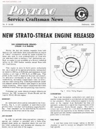
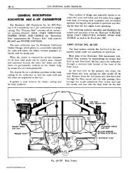
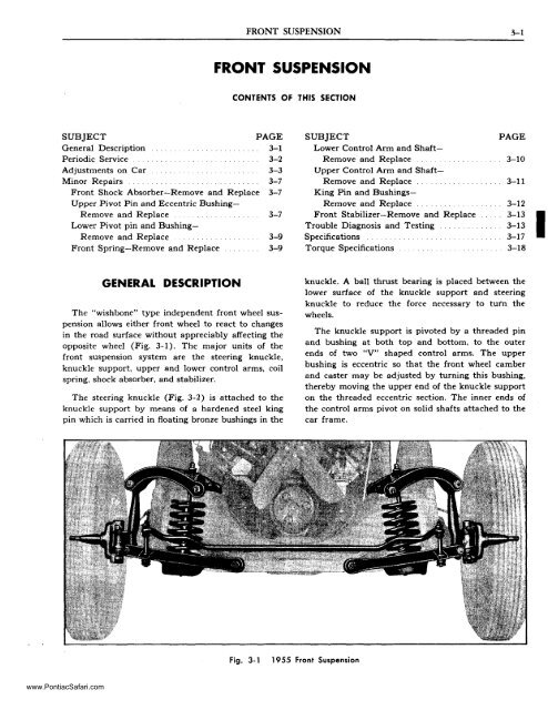
The "wishbone" type independent front wheel suspension<br />
allows either front wheel to react to changes<br />
in the road surface without appreciably affecting the<br />
opposite wheel (Fig. 3-1). The major units of the<br />
front suspension system are the steering knuckle,<br />
knuckle support, upper and lower control arms, coil<br />
spring, shock absorber, and stabilizer.<br />
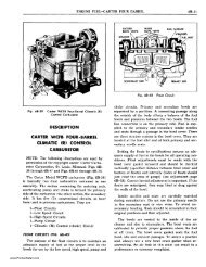
The steering knuckle (Fig. 3-2) is attached to the<br />
knuckle support by means of a hardened steel king<br />
pin which is carried in floating bronze bushings in the<br />
knuckle. A ball thrust bearing is placed between the<br />
lower surface of the knuckle support and steering<br />
knuckle to reduce the force necessary to tuI'n the<br />
wheels.<br />
The knuckle support is pivoted by a threaded pin<br />
and bushing at both top and bottom, to the outer<br />
ends of two "V" shaped control arms. The upper<br />
bushing is eccentric so that the front wheel camber<br />
and caster may be adjusted by turning this bushing,<br />
thereby moving the upper end of the knuckle support<br />
on the threaded eccentric section. The inner ends of<br />
the control arms pivot on solid shafts attached to the<br />
car frame.<br />
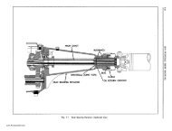
Fig. 3-1<br />
1955 <strong>Front</strong> <strong>Suspension</strong><br />
www.PontiacSafari.com
3-2 1955 PONTIAC SHOP MANUAL<br />
Caster Angle<br />
-ll!I'<br />
"NG "N<br />
~ a<br />
STEERING 0<br />
KNUCKLE<br />
1 (II!<br />
-=L-~<br />
ECCENTRIC BUSHING<br />
•• 1& ~\J ~ n ..:: \'"<br />
KNUCKLE<br />
~~09[.<br />
THRUST SEARING<br />
flOATING ()<br />
BUSHING --...<br />
;;:...----- El(PJlNSION PLUG<br />
Fig. 3-2<br />
Steering Knuckle and Related Parts<br />
The upper ends of the front coil springs seat in the<br />
frame front cross member. The lower ends of the<br />
springs are supported in stamped seats fastened to the<br />
lower control arms.<br />
A direct acting shock absorber of sealed construction<br />
is carried inside each front coil spring. The upper<br />
stud on the shock absorber is fastened to a bracket<br />
on the front cross member by a nut and lock nut. The<br />
bottom shock absorber stud fastens to the spring seat<br />
with a nut and lock nut. Noise insulation is provided<br />
by rubber grommets which fit over the shock absorber<br />
studs and prevent metal to metal contact between<br />
each stud and metal attaching parts.<br />
FRONT OF CAR<br />
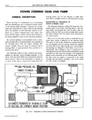
Fig. 3-3<br />
KINGPIN ~<br />
INCLINA nON \ g!<br />
ell OF<br />
KING PIN<br />
• I><<br />
W<br />
><br />
Caster Angle<br />
fCMlJ '" ANGLE<br />
.",<br />
u<br />
A front end stabilizer is used to provide stability<br />
and control body roll. It is fastened to the frame<br />
ahead of the springs with rubber mounts and is fastened<br />
at each end to the lower control arms by steel<br />
links having rubber grommets at their connecting<br />
ends.<br />
Rubber bumpers attached to the frame side members<br />
cushion the downward movement of the suspension<br />
system, ana bUmpers attached to the lower control<br />
arms cushion the upward movement.<br />
ell OF WHEEL<br />
PERIODIC SERVICE<br />
Periodic service of the front suspension consists of<br />
regular lubrication as outlined in the General Lubrication<br />
Section. No servicing of shock absorbers can be<br />
made since they are sealed at the factory. In :::ase of<br />
malfunction, they should be replaced.<br />
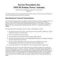
Fig. 3-4<br />
Camber and King Pin Inclination<br />
www.PontiacSafari.com
FRONT SUSPENSION 3-3<br />
ADJUSTMENTS ON CAR<br />
FRONT END ALIGNMENT-DEFINITIONS<br />
Proper adjustment of the following related front<br />
end factors constitutes wheel alignment:<br />
CASTER is the forward or backward tilt of the<br />
top of the king pin as compared to a true vertical<br />
position (Fig. 3-3). If the tilt of the pin is backward<br />
as shown, caster is positive; if forward, caster is negative.<br />
CAMBER is the outward tilt of front wheels at<br />
the top as shown in Fig. 3-4.<br />
KING PIN INCLINATION is the inward tilt of<br />
the king pin at the top (Fig. 3-4).<br />
TOE-IN is the drawing together of the front wheels<br />
so that they are closer at the front "B" than at the<br />
back "A" as shown in Fig. 3-S.<br />
TOE-OUT ON TURNS is the relationship between<br />
front wheels on turns. Since the front wheels must<br />
turn on different radius circles, the steering arms are<br />
inclined inward at the back to provide the correct<br />
turning angles (Fig. 3-6).<br />
~------------B------------~<br />
l<br />
FRONT<br />
Jo--------A--------t<br />
Fig. 3-5<br />
SEE<br />
~.O\)1.<br />
1.0~<br />
q?PECIFICATIONS<br />
Toe-in<br />
Since the above factors are inter-related, the average<br />
wheel alignment job involves a general check-up<br />
and corection which can be performed most efficiently<br />
by accurate testing and correcting equipment.<br />
INSPECTION BEFORE CHECKING<br />
FRONT END ALIGNMENT<br />
Before any attempt is made to check or adjust<br />
camber, caster, toe-in and king pin inclination, the<br />
following checks should be made on items which will<br />
aff ect steering of the car:<br />
Fig. 3-6<br />
Toe-out on turns<br />
1. Check tire inflation and bring to recommended<br />
pressure.<br />
2. Check front wheel bearing adjustment and correct<br />
if necessary.<br />
3. Check for looseness of king pin. If, with properly<br />
adjusted wheel bearings, the top of tire can be moved<br />
in and out as much as %" (with hands at top and<br />
bottom of tire, pushing with one while pulling with<br />
other) the bushings are excessively loose and must<br />
be replaced before alignment readings have any value.<br />
(Do not mistake the normal clearance in piv'ot shaft<br />
threaded bushings for king pin looseness.)<br />
4. Check for looseness of tie rod ends and replace<br />
if necessary.<br />
S. Check for run-out of wheels and tires which<br />
must not exceed %".<br />
6. Check wheels and tires for excessive unbalance<br />
which would affect steering.<br />
7. Check shock absorbers for action and replace if<br />
defective.<br />
8. See that car sets level by measuring vertical distance<br />
from top of lower control arm to underside of<br />
frame at a point directly in line with shock absorber,<br />
as shown in Fig. 3-7. This is commonly called front<br />
end "jounce" space.<br />
CHECKING FRONT END ALIGNMENT<br />
Point of greatest run-out of front wheels and tires<br />
must be marked so wheels can be positioned as shown<br />
in Fig. 3-8 when checking alignment. To mark wheels,<br />
hold a piece of chalk against the wheel rim or sidewall<br />
while wheel is spinning. Chalk will mark wheel or<br />
tire at point of greatest run-out.<br />
www.PontiacSafari.com
3-4 1955 PONTIAC SHOP MANUAL<br />
2. Check caster angle using any reputable front end<br />
aligning equipment. Specifications for caster are<br />
-1 0 +Yz o. When checking, it is necessary that readings<br />
be taken with car weight on the wheels, tires<br />
properly inflated, and vehicle level. Brakes must be<br />
held with a brake pedal depressor while checking<br />
caster.<br />
3. Do not change camber adjustment, if outside<br />
limits, until caster has been set.<br />
CHECKING CAMBER ANGLE<br />
1. Make sure operations under "Inspection Before<br />
Alignment" have been performed.<br />
Fig. 3-7<br />
Chalk mark in this position<br />
when checking caster, camber,<br />
king pin inclination<br />
Jounce Space Measurement<br />
Chalk mark in<br />
this position when<br />
checking toe-in and<br />
toe-out on turns<br />
location of point of greatest lateral run-out on<br />
front wheels when checking alignment factors<br />
Fig. 3-8<br />
Wheel Position for Checking Alignment<br />
Before checking front end alignment, jounce the<br />
car up and down at both the front and rear bumpers<br />
to make certain it is setting in its normal position.<br />
This is very important since caster and camber vary<br />
somewhat as the front of the car moves up and down.<br />
The specifications for front end alignment are based<br />
on the normal "curb weight" position of the car. Curb<br />
weight includes all equipment plus a full tank of gasoline.<br />
NOTE: Since the cars are quite frequently stiff<br />
when new, it is impossible to find the normal position<br />
by jouncing. For this reason, caster, camber and king<br />
pin inclination should not be checked on a new car<br />
until it is broken in.<br />
CHECKING CASTER ANGLE<br />
1. Make sure operations under "Inspection Before<br />
Alignment" have been performed.<br />
2. Check camber angle using any reputable front<br />
end aligning equipment. Specifications for camber<br />
are + Yz 0 -I-% o. When checking, it is necessary that<br />
readings be taken with car weight on the wheels, tires<br />
properly inflated, and vehicle level.<br />
3. Do not change camber adjustment, if outside<br />
limits, until caster has been set.<br />
CHECKING KING PIN INCLINATION<br />
If camber is correct or can be set to specifications,<br />
it is not necessary to check king pin inclination<br />
(KPI). When checking KPI, camber should be set to<br />
the nearest correct value obtainable. If KPI is correct,<br />
1 0 20', and camber is not correct, a bent steering<br />
knuckle is indicated and should be replaced. NOTE:<br />
If camber and KPI differ from specifications, approximately<br />
the same amount, but in opposite directions<br />
(camber greater-KPI less, and vice-versa), it is<br />
an indication that camber and KPI can be corrected<br />
at the eccentric bushing.<br />
CHECKING TOE-IN<br />
Check toe-in with a trammel, or with other reputable<br />
front end aligning equipment measuring from<br />
sidewall of tire or wheel felloes using methods given<br />
below.<br />
For Measuring By Trammel<br />
1. After moving car forward on level floor, chalk<br />
tread on both front tires at point 9" above floor.<br />
2. With trammel set at center to center distance of<br />
front tires make mark in chalk on each front tire<br />
exactly trammel width apart.<br />
3. Push car forward (never backward) until chalk<br />
with trammel marks is 9" above floor at rear of<br />
wheels.<br />
www.PontiacSafari.com
FRONT SUSPENSION 3-5<br />
4. Measure difference from trammel marks made<br />
when chalk was in front of wheel; if trammel marks<br />
are now greater than when marked at front, wheels<br />
toe-in by this amount (see specifications, page 3-17).<br />
For Equipment Measuring From<br />
Sidewall Or Wheel Felloes<br />
When using this type of equipment wheel run-out<br />
will have a very direct bearing on the readings. Since<br />
the allowable run-out is Ys" the readings could possibly<br />
be off as far as Ys" on each wheel if the effect of<br />
run-out is not cancelled. By taking the average of<br />
three readings with the wheel rotated 120° for each<br />
reading the error due to wheel run-out can be cancelled.<br />
This should be done as follows:<br />
1. After moving the car forward on level floor take<br />
first reading.<br />
1. Mark sidewall of both tires with the number<br />
"1" at rear of tire where instrument bears.<br />
3. At 120° intervals (i.e. % and 213 distance around<br />
the tire) mark the numbers "2" and "3" on both tires.<br />
4. Jack up and turn wheels until the number "2"<br />
is in the position which number "1" occupied when<br />
the first reading was taken.<br />
S. Push car back one foot and bring forward to<br />
position and take second reading. This reading will<br />
then be taken with the instrument bearing 120°<br />
around the wheel from where the first reading was<br />
taken.<br />
6. Use the same procedure for taking the third<br />
reading.<br />
7. Average the three readings to find the actual<br />
toe-in.<br />
4. Incorrect steering geometry may be caused by<br />
other incorrect front end adjustments, but generally<br />
indicates bent steering arms which must be replaced<br />
followed by a complete front end check.<br />
ADJUSTING FRONT END<br />
ADJUST FRONT WHEEL BEARINGS<br />
Two methods for adjusting front wheel bearings<br />
are given below. The first is the preferred method and<br />
should be used whenever possible.<br />
Torque Wrench Method<br />
l. Check to see that bearing cups are a press fit in<br />
hub and seated tight against shoulders.<br />
2. Check to see that bearing cones have a slip fit<br />
on spindles, and bores of cones have a light coating<br />
of wheel bearing lubricant to allow creep.<br />
3. Check fit of spindle nut on spindle threads. Nut<br />
MUST BE FREE RUNNING on threads; if not, remove<br />
all burrs from threads, keyslot, and cotter pin<br />
holes.<br />
4; With wheel off ground adjustment bearing as<br />
follows:<br />
a. Tighten bearing adjusting nut with a torque<br />
wrench to approximately 200 lb. in. (17 lb. ft.) to<br />
insure that all parts are properly seated.<br />
b. Back off nut and retighten to 4S-S0 lb. in. (Fig.<br />
3-9). (This should be measured by using Wrench<br />
KMO-652 with Adapter KMO-653 as when measuring<br />
rear axle pinion bearing preload).<br />
CHECKING TOE-OUT ON TURNS<br />
NOTE: Toe-out on turns should be checked only<br />
after any necessary corrections to camber, caster,<br />
and toe-in have been made.<br />
1. Make sure operations under "Inspection Before<br />
Alignment" have been performed.<br />
2. Check with any reputable front end aligning<br />
equipment using full floating turn tables. With front<br />
wheels resting on turn tables, turn wheels to left until<br />
left wheel has been turned 20° from straight ahead.<br />
The right wheel should then be turned 18° to 19°.<br />
3. Turn wheels to right until right wheel has been<br />
turned 20° from straight ahead. Left wheel should<br />
now be turned 18° to 19°.<br />
Fig. 3-9<br />
Adiusting Wheel Bearing Using Torque Wrench<br />
www.PontiacSafari.com
3-6 1955 PONTIAC SHOP MANUAL<br />
c. If cotter pin hole in spindle and slot in nut line<br />
up, insert cotter pin. Otherwise, bacl~ off adjusting<br />
nut to nearest line-up of slot and hole and insert cotter<br />
pin. Cut off excess length of cotter pin to prevent<br />
interference with static brush in front wheel dust cap.<br />
Hand Feel Method<br />
1. Jack up wheel and remove dust cap.<br />
2. Eliminate play of king pin by inserting wooden<br />
wedge between knuckle and king pin yoke on steering<br />
knuckle support.<br />
3. Tighten bearing adjusting nut with an 8" to 10"<br />
wrench using only arm and shoulder strength and<br />
only enough to insure that parts are properly seated.<br />
Back off nut until first perceptible looseness is felt in<br />
bearing when tested by grasping tire at top and bottom<br />
and shaking. Tighten nut until a slot of nut<br />
lines up with one of the cotter pin holes in knuckle.<br />
4. Insert new cotter pin and clinch, cutting off excess<br />
length to make sure ends of pin will not interfere<br />
with static brush in front wheel dust cap.<br />
5. Remove wedge, replace dust cap and lower car.<br />
Fig. 3-10<br />
Adjusting Caster or Camber<br />
SETTING CASTER<br />
NOTE: Caster adjustment should always be<br />
made before camber adjustment. If camber was<br />
found to be within specifications, make complete<br />
turns of eccentric bushing when setting caster<br />
so as not to disturb camber setting. It is good<br />
practice, however, to check camber after setting<br />
caster.<br />
1. Loosen eccentric bushing clamp bolt and turn<br />
bushing with Caster and Camber Adjusting Wrench<br />
J .. 5343 (Fig. 3-10) to give correct caster setting of<br />
-1 0 ±Yz 0 at each front wheel.<br />
2. When correct caster setting has been obtained,<br />
tighten clamp bolt only enough to prevent setting<br />
from changing; proceed with camber adjustment or<br />
check, as required.<br />
SETTING CAMBER<br />
1. Loosen clamp bolt and rotate eccentric bushing<br />
using Wrench J-5343 (Fig. 3-10) to give correct camber<br />
setting of +- Yz 0 -+- Yz 0 at each front wheel. It is<br />
never necessary to turn the eccentric bushing over Yz<br />
turn to obtain the maximum possible adjustment of<br />
camber. NOTE: If correct camber cannot be obtained,<br />
king pin inclination should be checked to determine<br />
if the steering knuckle is bent.<br />
2. Tighten eccentric bushing clamp bolt to 35-40<br />
lb. ft. torque.<br />
SETTING TOE-IN<br />
1. Remove horn button and set gear on high point<br />
of worm by turning steering wheel until mark on<br />
shaft is exactly at top. This mark locates the high<br />
point, or middle of gear travel.<br />
2. Loosen tie rod end clamp bolts and turn tie rod<br />
tubes an equal amount until toe-in is 0-1/6" (see<br />
page 3-4, Checking Toe-in). Turn right tie rod in direction<br />
of rotation of wheels, when car moves forward,<br />
to increase toe-in; turn left tie rod in opposite direction<br />
to increase toe-in.<br />
3. Check to see that front wheels are straight ahead<br />
by measuring from lower control arm inner shaft<br />
grease fitting to front of wheel rim on both sides. If<br />
measurement is not equal, turn both tie rod tubes in<br />
same direction (so as not to change toe-in) until<br />
measurements become equal. After making this adjustment<br />
it is very important to re-check toe-in since<br />
toe-in measurement is accurate only with wheels in<br />
straight ahead position.<br />
4. Tighten tie rod end clamp nuts to 18-20 lb. ft.<br />
torque, making sure that tie rod end bearings are<br />
horizontal and slots in tie rod tubes are toward bolts<br />
in clamps.<br />
www.PontiacSafari.com
FRONT SUSPENSION 3-7<br />
MINOR REPAIRS<br />
fRONT SHOCK ABSORBER-REMOVE AND REPLACE<br />
1. Raise car on hoist, or jack up front end so<br />
weight of car is fully off front wheels.<br />
2. Loosen and remove two nuts from bottom stud<br />
on shock absorber. NOTE: Shock absorber must not<br />
turn while loosening nuts. If necessary, use water<br />
pump pliers inserted through coils of front spring to<br />
hold shock absorber reservoir tube from turning (Fig.<br />
3-11). Spring coils can be pried apart with large screw<br />
driver or similar tool to provide sufficient space to<br />
insert pliers.<br />
3. Remove grommet retainer and grommet. Compress<br />
shock absorber as far as possible by pushing<br />
the lower section up. Tool J-5536 (Fig. 3-12) can be<br />
used for compressing shock absorber.<br />
4. If car is on hoist, lower hoist until front wheel<br />
is at shoulder height.<br />
S. Working over front wheel, remove two nuts<br />
holding front shock absorber upper bracket to frame.<br />
6. Remove shock absorber with upper bracket upward<br />
out of coil spring and hole in frame. NOTE: On<br />
left side, removal will be simplified by first removing<br />
upper bracket from shock absorber.<br />
7. Remove bracket and grommets from old shock<br />
absorber by removing two nuts on shock absorber<br />
upper stud, and install new shock absorber.<br />
8. Install new shock absorber and bracket by reversing<br />
the procedure in Steps 1 through 6. Make<br />
sure all grommets and retainers are correctly installed<br />
(see Fig. 3-13 for details of mounting).<br />
Fig. 3-12<br />
Compressing Shock Absorber<br />
With Tool J-5536<br />
UPPER PIVOT PIN AND ECCENTRIC BUSHING<br />
REMOVE AND REPLACE<br />
REMOVE<br />
NOTE: A clearance of from .011" to .020" is<br />
provided between the threaded pins and bushings.<br />
The threaded surface automatically provides<br />
perfect side adjustment and where roll is<br />
always in the same direction, the two members<br />
forming the bearing are virtually tied together<br />
even when one fits loosely within the other. This<br />
permits ample space for lubrication, rolling action,<br />
and free action for oscillation. The rolling<br />
action minimizes wear and accounts for long life<br />
of the pin and bushing. If bushings are properly<br />
lubricated and clearances are within specification,<br />
they will not be noisy. UNDER NO<br />
CONDITIONS SHOULD ANY CHANGES BE<br />
MADE TO REDUCE SPECIFIED THREAD<br />
CLEARANCE GIVEN ABOVE.<br />
Fig. 3-11<br />
Holding Shock Absorber to loosen<br />
or Tighten Retaining Nuts<br />
1. Place a jack under lower control arm, raise wheel<br />
off floor, and remove wheel.<br />
2. Remove nut from rear end of upper pivot pin<br />
(Fig. 3-14).<br />
3. Remove threaded pivot pin. NOTE: To prevent<br />
damage to brake hose, fasten knuckle support to<br />
frame upper rubber bumper.<br />
www.PontiacSafari.com
3-8 1955 PONTIAC SHOP MANUAL<br />
o<br />
o~ 8.915-HEX NUT<br />
....<br />
O~ 7.377-BUSHING<br />
7.364-BRACKET ASSY.<br />
~ 7.377-BUSHING<br />
Fig. 3-14<br />
Upper Pivot Pin Assembly<br />
.,~- 7.345-SHOCK ABSORBER<br />
g<br />
~,.m_,","~G<br />
with chassis lubricant and install pin and lockwasher<br />
in control arm and knuckle support. See that pivot<br />
pin bolt head (with lockwasher) is turned up tigqtly<br />
against surface of control arm (50-55 lbs. ft. torque).<br />
4. Install pivot pin nut and lockwasher and tighten<br />
nut securely against surface of control arm (50-55<br />
lb. ft. torque). NOTE: Make visual inspection to see<br />
that bolt head and nut are turned up securely against<br />
metal of control arm to insure firm seating. If not,<br />
apply additional torque to seat parts properly.<br />
~ 8.915-HEX NUT<br />
Fig. 3- 13<br />
<strong>Front</strong> Shock Absorber and Mounting Parts<br />
4. Loosen clamp bolt and remove eccentric bushing<br />
from knuckle support.<br />
REPLACE<br />
1. Position seals over ends of upper control arms as<br />
shown in Fig. 3-15.<br />
2. Install new eccentric bushing in knuckle support<br />
so it is centralized (projects same amount both ends).<br />
3. Position knuckle support with bushing in forked<br />
end of upper control arm. Coat threads of pivot pin<br />
Fig. 3-15<br />
Seals Positioned for Assembly of Pivot Pin<br />
www.PontiacSafari.com
FRONT SUSPENSION 3-9<br />
NOTE: This operation is only necessary when<br />
knuckle support lower bushing is to be removed. Omit<br />
this step if lower pivot pin only is to be removed.<br />
3. Remove nut from rear of lower pivot pin (Fig.<br />
3-16).<br />
4. Remove lower pivot pin.<br />
5. If knuckle support lower bushing is to be replaced,<br />
remove upper pivot pin. NOTE: This operation<br />
is only necessary when knuckle support lower<br />
bushing is to be removed. Omit this step if lower<br />
pivot pin only is to be removed.<br />
6. Clamp knuckle support in vise, remove knuckle<br />
support lower bushing and install new bushing. Bushing<br />
must be very firmly tightened in knuckle support<br />
so there is no clearance between the bushing shoulder<br />
and knuckle support (250 lb. ft. torque).<br />
Fig. 3-16<br />
lower Pivot Pin Assembly<br />
5. Stretch rubber seals over end of control arm into<br />
position over threads of pin as shown in Fig. 3-14.<br />
6. Lubricate pivot pin, install front wheel, lower<br />
car, and check front wheel alignment.<br />
LOWER PIVOT PIN AND BUSHING<br />
REMOVE AND REPLACE<br />
NOTE: It will be noted that in some of the <strong>Front</strong><br />
<strong>Suspension</strong> Minor Repair operations involving<br />
control arm bushings, torque tightness specifications<br />
in excess of the usually available torque<br />
wrenches are given (250-455 lb. ft.). It is not intended<br />
that parts having such high torque specifications<br />
be tightened with a torque wrench; these<br />
torque specifications are those used in production<br />
and are listed to give the mechanic an idea of<br />
the approximate force required to insure secure<br />
seating of front suspension parts. In all cases involving<br />
tightening of front suspension control<br />
arm bushings, pivot pins and nuts, a visual inspection<br />
of the assembly must be made after<br />
tightening to see that a positive metal to metal<br />
seating has resulted between the bushing shoulder,<br />
pivot pin head, or nut and the metal of the control<br />
arm or steering knuckle support.<br />
1. Place jack under lower control arm, raise wheel<br />
off floor and remove wheel and brake drum assembly.<br />
2. If knuckle support lower bushing is to be replaced,<br />
remove brake backing plate from knuckle.<br />
7. If upper pivot pin was removed in Step 5, place<br />
knuckle support in position and install upper pivot<br />
pin (see page 3-7).<br />
8. Position rubber seals at lower pivot pin bushing<br />
(Fig. 3-16). Hold bushing with knuckle support in a<br />
central position in forked end of lower control arm<br />
and install lower pivot pin and lockwasher after coating<br />
threads on pin with chassis lubricant. NOTE:<br />
Lower pivot pin must be centered, within one thread,<br />
between ends of control arm after lock nut has been<br />
tightened (Fig. 3-16).<br />
9. With hex head of pivot pin firmly tightened<br />
against control arm (50-55 lb. ft.), install pivot pin<br />
nut and lockwasher and tighten until securely seated<br />
against control arm (50-55 lb. ft.).<br />
10. Reinstall brake backing plate (if removed in<br />
Step 2). Install wheel and brake drum.<br />
11. Lubricate pivot pins, lower car, and check<br />
wheel alignment.<br />
FRONT SPRING-REMOVE AND REPLACE<br />
<strong>Front</strong> spring replacement requires use of a chain<br />
hoist and car stand. If a chain hoist is not available<br />
the operation can be performed by using three car<br />
stands and a GOOD hydraulic floor jack. CAUTION:<br />
Do not attempt to use floor jack method unless a good<br />
hydraulic jack with positive control over lowering a<br />
load SLOWLY is available.<br />
CHAIN HOIST METHOD<br />
1. Lift car with chain hoist so wheels are 8" off<br />
floor and place car stand under inner side of lower<br />
control arm spring pad from which coil spring is to<br />
www.PontiacSafari.com
3-10 1955 PONTIAC SHOP MANUAL<br />
be removed. Lower car until it touches top of car<br />
stand. Remove wheel.<br />
2. Remove shock absorber (page 3-7).<br />
3. Disconnect lower end of stabilizer link at lower<br />
control arm.<br />
4. Remove lower pivot pin nut and pin from bushing.<br />
S. Raise the car slowly with chain hoist and remove<br />
coil spring.<br />
6. When installing spring, have car elevated on<br />
chain hoist and place bottom of spring in seat on<br />
lower control arm. Top of spring may be identified<br />
since it is flat and bottom is not. End of coil at bottom<br />
of spring must index with hole provided in spring<br />
seat in lower control arm.<br />
7. Lower chain hoist gradually, checking to see<br />
that spring is correctly seated top and bottom.<br />
8. Install lower pivot pin and nut (see page 3-9)<br />
and connect stabilizer link.<br />
9. Install shock absorber (page 3-7).<br />
10. Lubricate pivot pin, install front wheel, lower<br />
car and check wheel alignment. NOTE: Wheel alignment<br />
must be checked since replacement of front<br />
springs will usually affect jounce space and, therefore,<br />
wheel alignment.<br />
FLOOR JACK METHOD<br />
l. Raise front end of car with jack until wheels are<br />
about 10" above floor and place car stand under<br />
frame side member on each side of car forward of<br />
front door hinge pillar so car will be firmly supported.<br />
2. Place car stand under lower control arm of<br />
spring which is not to be replaced. The two stands<br />
under the frame are almost at car center of balance<br />
so car will asume a horizontal position on the two<br />
stands when jack is removed unless the extra stand is<br />
placed under control arm to keep car front end elevated.<br />
3. Place floor jack under lower control arm spring<br />
seat from which spring is to be removed and raise<br />
jack until it touches spring seat.<br />
4. Remove wheel on side of car where spring is to<br />
be removed.<br />
5. Remove shock absorber (page 3-7).<br />
6. Disconnect lower end of stabilizer link at lower<br />
control arm.<br />
7. Remove lower pivot pin nut and pin from bushing.<br />
8. Slowly lower jack until coil spring is fully extended<br />
and remove spring.<br />
9. To install spring have jack pad under spring<br />
seat and place spring in seat on lower control arm<br />
with end of coil at bottom of spring indexing with<br />
hole in spring seat. Top of spring may be easily identified<br />
since it is flat and bottom of spring is not.<br />
10. Raise jack gradually, checking to see that<br />
spring is correctly seated top and bottom.<br />
11. Install lower pivot pin and nut (page 3-9) and<br />
connect stabilizer bar to lower control arm.<br />
12. Install shock absorber (page 3-7).<br />
13. Lubricate pivot pin, install front wheel, lower<br />
car and check wheel alignment. NOTE: Wheel alignment<br />
must be checked since replacement of front<br />
springs will usually affect jounce space and, therefore,<br />
wheel alignment.<br />
LOWER CONTROL ARM AND SHAFT<br />
REMOVE AND REPLACE<br />
NOTE: See Note under heading "Lower Pivot<br />
Pin and Bushing-Remove and Replace".<br />
l. Follow procedure for removing front spring as<br />
outlined on page 3-9.<br />
2. Remove four nuts and lockwashers holding lower<br />
control arm shaft to frame cross member and remove<br />
control arm and shaft assembly.<br />
3. Remove shaft from control arm by removing<br />
front and rear threaded bushings from shaft and control<br />
arm.<br />
4. When installing a new lower control arm, it is<br />
necessary to cut a thread for the bushing in extruded<br />
portion of arm. The shaft bushing has threads on inside<br />
and outside so that as the bushing threads onto<br />
the pivot shaft, the outside thread on bushing cuts its<br />
own thread in lower control arm. To install pivot<br />
shaft in new arm proceed as follows:<br />
a. Place tool J-1052 in position and expand until<br />
distance between inner faces of arms is 11%" (Fig.<br />
3-17 and 3-18).<br />
b. Place pivot shaft with rubber seals in position<br />
in control arm.<br />
c. After lubricating pivot shaft threads with chassis<br />
lubricant, start bushing on pivot shaft and into<br />
arm at same time. Tighten until bushing flange is<br />
firmly seated against metal of control arm (385-4SS<br />
lb. ft. torque).<br />
www.PontiacSafari.com
FRONT SUSPENSION 3-11<br />
Fig. 3-19 Upper Control Arm Spreader J-5324<br />
Positioned in Upper Control Arm<br />
Fig. 3- 17 Lower Control Arm Spreader J-l052<br />
Positioned in Lower Control Arm<br />
5. Position lower control arm and shaft on frame<br />
cross member and install retaining nuts and lockwashers.<br />
Tighten nuts to 70-80 lb. ft. torque.<br />
6. Complete installation by following procedure<br />
for installing spring as outlined on page 3-9.<br />
f[L. --<br />
I 1 112"<br />
, ± 3/64"<br />
i<br />
11 112"<br />
± 3/32"<br />
I<br />
7. Lower car, lubricate control arm shaft and lower<br />
pivot pin, and check front wheel alignment.<br />
UPPER CONTROL ARM AND SHAFT<br />
REMOVE AND REPLACE<br />
NOTE: See "Note" under heading "Lower Pivot<br />
Pin and Bushing-Remove and Replace".<br />
1. Place jack under lower control arm, raise wheel<br />
off floor and remove wheel.<br />
Fig. 3- 18 Correct Installation of Shaft<br />
In Lower Control Arm<br />
d. Center pivot shaft in control arm and install<br />
other bushing being sure threads index so there is no<br />
bind. Tighten until bushing flange is firmly seated<br />
against metal of control arm (385-455 lb. ft. torque).<br />
Remove special tool J-I052.<br />
e. Check to see that distance between inner faces<br />
of shaft ends of control arm is 11 %" plus or minus<br />
~!~2'" Also check to see that distances from center of<br />
pivot shaft bolt holes to inside faces of arm are equal<br />
at each end (Fig. 3-18). Turn pivot shaft in arm to<br />
centralize if distance is not equal.<br />
2. Remove upper pivot pin following procedure on<br />
page 3-7.<br />
3. Remove two bolts and self-locking nuts holding<br />
upper control arm shaft to frame and remove arm<br />
and shaft assembly. (Nuts can be reached through<br />
access holes in bottom of front cross member.)<br />
4. Remove shaft from control arm by removing<br />
front and rear threaded bushings.<br />
S. Install pivot shaft in new arm as follows (the<br />
procedure is very similar to that used for lower control<br />
arm).<br />
a. Place tool J-5324 in position and expand until<br />
distance between inner faces of arms is 6~'l!\" (Fig.<br />
3-19).<br />
www.PontiacSafari.com
3-12 1955 PONTIAC SHOP MANUAL<br />
b. Place pivot shaft with new rubber seals in position<br />
in control arm.<br />
c. After lubricating pivot shaft threads with chassis<br />
lubricant, start bushing on pivot shaft and into<br />
arm at same time. Tighten so bushing flange is firmly<br />
seated against control arm (326-380 lb. ft. torque).<br />
d. Center pivot shaft in control arm and install<br />
other bushing being sure threads index so there is no<br />
bind. Tighten so bushing flange is firmly s'eated<br />
against control arm (326-380 lb. ft. torque). Remove<br />
special spreader tool.<br />
e. Check to see that distance between inner faces of<br />
shaft ends of control arm is correct (Fig. 3-20). Also<br />
check to see that pivot shaft is equalized in arm by<br />
measuring from bolt hole to arm at each end of shaft.<br />
Turn shaft in arm to centralize if distances from each<br />
bolt hole to arm are not equal. NOTE: Frictional<br />
drag of shaft in bushings should not exceed 12 lb. in.<br />
Fig. 3-21 Reaming Steering Knuckle<br />
with Reamer J-1324<br />
KING PIN AND BUSHINGS-REMOVE AND REPLACE<br />
REMOVE<br />
1. Jack up wheel under lower control arm and remove<br />
wheel and brake drum assembly.<br />
2. Remove backing plate without disconnecting<br />
brake hose. Place backing plate out of way' so as to<br />
avoid any strain on brake hose.<br />
3. Remove king pin lock pin (Fig. 3-2).<br />
Fig. 3-20 Correct Installation of Shaft<br />
in Upper Control Arm<br />
6. Position upper control arm and shaft on frame<br />
cross member and install two bolts and self-locking<br />
nuts. Tighten nuts to 80-85 lb. ft. torque. NOTE:<br />
Nuts must be installed and tightened by means of an<br />
extension inserted through access holes in front cross<br />
member.<br />
7. Complete installation by following procedure for<br />
installing upper pivot pin (page 3-7).<br />
8. Lubricate control arm shaft and upper pivot<br />
pin, replace wheel, lower car, and check front wheel<br />
alignment.<br />
4. Remove lower expansion plug under king pin by<br />
driving punch through upper expansion plug. If necessary,<br />
king pin can be driven up to remove upper<br />
expansion plug.<br />
5. Drive out king pin.<br />
6. Lift floating bushings from steering knuckle.<br />
REPLACE<br />
1. Using Expansion Plug Reamer J-1324 (Fig.<br />
3-21), clean up recesses in steering knuckle where<br />
metal was up set over expansion plugs.<br />
2. Lubricate new bushings and position in knuckle<br />
(Fig. 3-22). NOTE: King pin bushings require no<br />
special alignment when being installed in steering<br />
knuckle.<br />
www.PontiacSafari.com
FRONT SUSPENSION 3-13<br />
EXPANSION PLUG<br />
5. Install expansion plugs on both ends of king pin,<br />
staking them securely in place in steering knuckle.<br />
NOTE: Plugs must be staked securely so that lubricant<br />
will be retained in king pin bushings.<br />
6. Install brake backing plate. (Tighten nuts to<br />
50-60 lb. ft. torque.)<br />
7. Install wheel and drum assembly and lower car.<br />
8. Lubricate king pin being certain that lubricant<br />
does not leak past expansion plug. Stake plugs more<br />
securely if necessary to prevent leakage.<br />
FRONT STABILIZER-REMOVE AND REPLACE<br />
1. Disconnect both links from stabilizer bar by removing<br />
nuts from top of link and pulling downward<br />
from bracket on lower control arm.<br />
2. Remove bolts holding two stabilizer bar brackets<br />
to frame and remove stabilizer bar.<br />
Fig. 3-22<br />
King Pin Bushings Positioned<br />
in Steering Knuckle<br />
3. Position steering knuckle on knuckle support<br />
and install new king pin. Make sure thrust bearing<br />
(Fig. 3-2) is correctly installed below knuckle support.<br />
Check to see that knuckle is not binding or does<br />
not have more than .005" end play. If end play exceeds<br />
. 005", install king pin thrust bearing shims to reduce<br />
end play to .005" or less.<br />
4. Drive in king pin lock pin.<br />
3. Install stabilizer bar on frame by placing two<br />
brackets over rubber insulators on bar and install<br />
mounting bolts to frame. When properly installed the<br />
central portion of the bar will be downward and toward<br />
rear of car.<br />
4. Place rubber grommet above and below lower<br />
control arm bracket and above and below eye of bar<br />
with front stabilizer link spacer in between and insert<br />
link from below .<br />
5. Install nut on each link, drawing it down as far<br />
as possible. Lock with lock nut.<br />
TROUBLE DIAGNOSIS AND TESTING<br />
HARD STEERING<br />
CAUSE<br />
REMEDY<br />
1. Low or uneven tire pressure.<br />
2. Steering gear or connections adjusted too tight.<br />
3. Insufficient or incorrect lubricant used.<br />
4. Excessive caster.<br />
5. <strong>Suspension</strong> arms bent or twisted.<br />
l. Inflate tires to recommended pressure.<br />
2. Test steering system for binding with front wheels<br />
off floor. Adjust as necessary and lubricate.<br />
3. Check lubricant in steering gear and lubricate<br />
steering system as required.<br />
4. Check caster and adjust as necessary.<br />
5. Check wheel alignment by testing camber and<br />
caster. If arms are out of car, check against new<br />
arms. Replace arms if bent.<br />
www.PontiacSafari.com
3-14 1955 PONTIAC SHOP MANUAL<br />
CAUSE<br />
6. <strong>Front</strong> spring sagged.<br />
7. Frame bent or broken.<br />
8. Steering knuckle bent.<br />
9. King pin galled or frozen in bushing.<br />
REMEDY<br />
6. Check front end jounce space (Fig. 3-7). Dimensions<br />
should be approximately the same on both<br />
sides. Compare dimensions with those on car having<br />
about same mileage and equipment and believed<br />
to be standard. Replace front springs if<br />
sagged.<br />
7. Repair or replace frame as necessary.<br />
8. Replace with new knuckle.<br />
9. Replace pin and bushings.<br />
EXCESSIVE PLA Y OR LOOSENESS IN STEERING<br />
CAUSE<br />
1. Steering gear or connections adjusted too loose<br />
or worn.<br />
2. Steering knuckle bushings worn.<br />
3. <strong>Front</strong> wheel bearings incorrectly adjusted or worn.<br />
REMEDY<br />
1. Adjust or install new parts as necessary.<br />
2. Install new bushings.<br />
3. Adjust bearings or replace with new parts as necessary.<br />
ERRATIC STEERING ON APPLICATION OF BRAKES<br />
CAUSE<br />
1. Oil or brake fluid on brake lining.<br />
2. Brakes incorrectly or unevenly adjusted.<br />
3. <strong>Front</strong> springs weak.<br />
4. Low or uneven tire pressure.<br />
5. Insufficient or uneven caster.<br />
6. Steering knuckle bent.<br />
REMEDY<br />
1. Replace lining and correct leak.<br />
2. Adjust brakes.<br />
3. Replace with new springs.<br />
4. Inflate tires to proper pressure.<br />
5. Check and adjust caster as necessary.<br />
6. Replace knuckle.<br />
CAR PULLS TO ONE SIDE<br />
CAUSE<br />
1. Low or uneven tire pressure.<br />
2. Incorrect or uneven caster or camber.<br />
3. Wheel bearings adjusted too tight.<br />
4. <strong>Front</strong> springs sagged.<br />
5. Toe-in incorrect.<br />
6. Oil or brake fluid on brake lining.<br />
REMEDY<br />
1. Inflate tires to recommended pressure.<br />
2. Check caster and camber and correct by adjustment<br />
or replacing parts.<br />
3. Adjust wheel bearings.<br />
4. Check as outlined under Hard Steering (page<br />
3-13, Step 6). Sagged springs should be replaced.<br />
5. Adjust tie rods to make front wheels toe-in proper<br />
amount.<br />
6. Replace linings and correct leak.<br />
www.PontiacSafari.com
FRONT SUSPENSION 3-15<br />
CAUSE<br />
7. Brakes incorrectly or unevenly adjusted.<br />
8. Steering knuckle or knuckle support bent.<br />
9. Frame bent or broken.<br />
10. Shock absorbers inoperative.<br />
7. Adjust brakes.<br />
REMEDY<br />
8. Replace with new parts.<br />
9. Check frame for proper alignment and breakage.<br />
Repair or replace frame as necessary.<br />
10. Check and replace shock absorbers if necessary.<br />
11. Rear wheels not tracking with front wheels.<br />
12. Rear axle shifted (spring U bolts loose or center<br />
bolt sheared).<br />
11. Check alignment of rear wheels with front wheels<br />
and correct as necessary. Check alignment of<br />
frame.<br />
12. Check spring U bolts for looseness. Measure from<br />
rear spring front bolt to axle housing. This distance<br />
should be equal on both sides of car.<br />
SCUFFED TIRES<br />
CAUSE<br />
1. Tire improperly inflated.<br />
2. Toe-in incorrect.<br />
3. Excessive wheel or tire runout.<br />
4. Steering knuckle bushings worn.<br />
S. Uneven camber.<br />
6. Incorrect toe-out on turns.<br />
7. <strong>Suspension</strong> arms bent or twisted.<br />
8. Steering knuckle bent.<br />
9. Excessive speed on turns.<br />
REMEDY<br />
1. Inflate tire to recommended pressure.<br />
2. Adjust tie rods to make front wheels toe-in proper<br />
amount.<br />
3. Check for wheel and tire wobble. See that wheels<br />
and tires are properly mounted.<br />
4. I nstall new bushings.<br />
S. Check camber and adjust as necessary.<br />
6. Replace steering knuckle arms with new ones.<br />
7. Check camber, king pin inclination and caster.<br />
Replace arms with new ones if bent.<br />
8. Replace with new knuckle.<br />
9. Caution driver.<br />
CUPPED TIRES<br />
1. Improper toe-in.<br />
CAUSE<br />
REMEDY<br />
1. Check toe-in with trammel and adjust.<br />
2. Tires improperly inflated.<br />
3. Wheels, tires or brake drums out of balance.<br />
4. Dragging brakes (incorrectly adjusted).<br />
S. Worn steering knuckle bushings or wheel bearings<br />
incorrectly adjusted or worn.<br />
6. Uneven camber.<br />
7. Steering knuckle bent.<br />
8. Excessive mileage without rotating tires.<br />
2. Inflate tires to recommended pressure.<br />
3. Balace wheels and tires. Also check for eccentric<br />
or bulged tires and replace as necessary.<br />
4. Adjust brakes.<br />
S. Adjust or replace parts as necessary.<br />
6. Check camber and adjust as necessary.<br />
7. Replace with new knuckle.<br />
8. Rotate tires every 4000 miles.<br />
www.PontiacSafari.com
3-16 1955 PONTIAC SHOP MANUAL<br />
fRONT WHEEL SHIMMY<br />
CAUSE<br />
1. Low or uneven tire pressure.<br />
2. Wheels, tires or brake drums out of balance.<br />
3. Excessive wheel or tire runout.<br />
4. Shock absorbers inoperative.<br />
S. Steering connections incorrectly adjusted or worn.<br />
6. Steering gear incorrectly adjusted.<br />
7. <strong>Front</strong> wheel bearings incorrectly adjusted or worn.<br />
8. Incorrect or uneven caster.<br />
9. Steering knuckle bushings worn.<br />
10. Toe-in incorrect.<br />
11. Steering knuckle bent.<br />
12. Eccentric or bulged tires.<br />
13. Stabilizer inoperative.<br />
REMEDY<br />
1. Inflate tires to recommended pressure.<br />
2. Balance wheels and tires. Also check for out-ofbalance<br />
brake drums and for eccentric or bulged<br />
tires and replace as necessary.<br />
3. Check for wheel and tire wobble and radial runout.<br />
See that wheels and tires are properly<br />
mounted.<br />
4. Check and replace if necessary.<br />
S. Adjust or install new parts as necessary.<br />
6. Adjust steering gear.<br />
7. Adjust bearings or replace with new parts as necessary.<br />
8. Check caster and adjust as necessary.<br />
9. Install new bushings.<br />
10. Adjust tie rods to make front wheels toe-in proper<br />
amount.<br />
11. Replace with new knuckle.<br />
12. Replace with new tires.<br />
13. Inspect bushings and links, replacing worn parts.<br />
fRONT WHEEL TRAMP<br />
CAUSE<br />
1. Wheels, tires or brake drums out of balance.<br />
2. Wheel or tire not concentric.<br />
3. Shock absorbers inoperative.<br />
4. Stabilizer inoperative.<br />
REMEDY<br />
1. Balance wheels and tires. Also check for out-ofbalance<br />
brake drums and for eccentric or bulged<br />
tires and replace as necessary.<br />
2. Replace wheel or tire.<br />
3. Replace shock absorbers.<br />
4. Inspect bushings and links replacing worn parts.<br />
CAR WANDERS<br />
CAUSE<br />
1. Low or uneven tire pressure.<br />
2. Steering gear or connections adjusted too loose or<br />
worn.<br />
3. Steering gear or connections adjusted too tight.<br />
4. Steering knuckle bushings worn.<br />
REMEDY<br />
1. Inflate tires to recommended pressure.<br />
2. Adjust or install new parts as necessary.<br />
3. Test steering system for binding with front wheels<br />
off floor. Adjust as necessary and lubricate.<br />
4. Install new bushings.<br />
www.PontiacSafari.com
FRONT SUSPENSION 3-17<br />
CAUSE<br />
REMEDY<br />
5. Improper toe-in.<br />
6. Incorrect or uneven caster or camber.<br />
5. Adjust tie rods to make front wheels toe-in proper<br />
amount.<br />
6. Check caster and camber and adjust as necessary.<br />
7. Steering knuckle bent.<br />
8. King pin bent.<br />
9. Rear axle shifted. (Spring U bolts loose or center<br />
bolt sheared.)<br />
10. Stabilizer inoperative.<br />
7. Replace with new knuckle.<br />
8. Replace with new pin. Drive lock pin in securely<br />
but not excessively.<br />
9. Check spring U bolts for looseness. Also measure<br />
from rear spring front bolt to housing. This distance<br />
should be equal on both sides of car.<br />
10. Inspect bushings and links, replacing worn parts.<br />
11. King pins or bushings tight.<br />
12. Bind in lower or upper control arm shaft.<br />
13. Bind in rear spring shackles or dry rear springs.<br />
14. Excessive backlash in steering gear.<br />
11. Replace as necessary.<br />
12. Free up or replace parts.<br />
13. Replace shackle bushing and lubricate springs.<br />
14. Adjust steering gear.<br />
ROAD SHOCKS<br />
CAUSE<br />
1. High air pressure in tires.<br />
2. Steering gear or connections incorrectly adjusted.<br />
3. Excessive caster.<br />
4. Shock absorbers inoperative.<br />
5. <strong>Front</strong> springs weak or sagged.<br />
6. Wrong type or size of tires used.<br />
7. Steering knuckle bent.<br />
REMEDY<br />
1. Bleed to recommended pressure. CAUTION: Do<br />
not "bleed" tires when warm.<br />
2. Adjust steering gear and connections.<br />
3. Check caster and adjust as necessary.<br />
4. Replace shock absorbers.<br />
5. Check as outlined under Hard Steering (page<br />
3-13, Step 6). Replace weak or sagged springs.<br />
6. Install new tires of correct type and size.<br />
7. Replace with new knuckle.<br />
SPECIFICATIONS<br />
Alignment (curb weight)<br />
Caster angle<br />
Camber angle<br />
King pin inclination<br />
Toe-in<br />
Shock absorber<br />
Collapsed length<br />
(ends of studs)<br />
.. -1° ±Yz0<br />
+Yz0 +%0<br />
. 1°20'<br />
.. 0" to l;i6"<br />
with trammel 9" above floor<br />
.. Approx. 13"<br />
Shock Absorber (Cont.)<br />
Extended length<br />
(ends of studs)<br />
Pivot pin to bushing clearance<br />
(upper and lower)<br />
Steering knuckle end play<br />
(on support)<br />
Approx. 17 1 ~)(;"<br />
.011"-.020"<br />
... 005" max.<br />
www.PontiacSafari.com
3-18<br />
1955 PONTIAC SHOP MANUAL<br />
TORQUE SPECIFICATIONS<br />
Upper Control Arm Inner Shaft<br />
to Frame Bolts<br />
Lower Control Arm Inner Shaft<br />
to Frame Nuts<br />
Eccentric Bushing Clamp Bolt<br />
Tie Rod Clamp Nuts<br />
Knuckle Support Pivot Pin<br />
Upper and Lower<br />
Knuckle Support Pivot Pin Nut<br />
Upper and Lower<br />
Lb. Ft. Torque<br />
80-85<br />
70-80<br />
.. 35-40<br />
........ 18-20<br />
SO-55<br />
.. SO-55<br />
Brake Backing Plate to Steering<br />
Knuckle Nuts<br />
Steering Knuckle Support<br />
Lower Bushing<br />
Lower Control Arm Inner<br />
Shaft Bushing<br />
Upper Control Arm Inner<br />
Shaft Bushing<br />
.... 50-60<br />
.... 250-260*<br />
... 385-455*<br />
.326-380*<br />
*Torque values marked with an asterisk are values<br />
used in production and are for reference only. These<br />
parts must be tightened with sufficient torque to secure<br />
firm metal-to-metal seating of the parts in question<br />
as instructed in the text.<br />
(<br />
J-1052<br />
J-1324<br />
J-5536<br />
J-5324<br />
J-5343<br />
SPECIAL TOOLS-FRONT SUSPENSION<br />
J-1052<br />
J-1324<br />
J-5324<br />
J-5343<br />
J-5536<br />
Lower Control Arm Spreader<br />
Steering Knuckle Expansion Plug Hole Reamer<br />
Upper Control Arm Spreader<br />
Caster and Camber Adjusting Wrench<br />
Shock Absorber Remover and Replacer<br />
www.PontiacSafari.com