Front Suspension
Front Suspension
Front Suspension

You also want an ePaper? Increase the reach of your titles
YUMPU automatically turns print PDFs into web optimized ePapers that Google loves.
3-6 1955 PONTIAC SHOP MANUAL<br />
c. If cotter pin hole in spindle and slot in nut line<br />
up, insert cotter pin. Otherwise, bacl~ off adjusting<br />
nut to nearest line-up of slot and hole and insert cotter<br />
pin. Cut off excess length of cotter pin to prevent<br />
interference with static brush in front wheel dust cap.<br />
Hand Feel Method<br />
1. Jack up wheel and remove dust cap.<br />
2. Eliminate play of king pin by inserting wooden<br />
wedge between knuckle and king pin yoke on steering<br />
knuckle support.<br />
3. Tighten bearing adjusting nut with an 8" to 10"<br />
wrench using only arm and shoulder strength and<br />
only enough to insure that parts are properly seated.<br />
Back off nut until first perceptible looseness is felt in<br />
bearing when tested by grasping tire at top and bottom<br />
and shaking. Tighten nut until a slot of nut<br />
lines up with one of the cotter pin holes in knuckle.<br />
4. Insert new cotter pin and clinch, cutting off excess<br />
length to make sure ends of pin will not interfere<br />
with static brush in front wheel dust cap.<br />
5. Remove wedge, replace dust cap and lower car.<br />
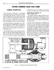
Fig. 3-10<br />
Adjusting Caster or Camber<br />
SETTING CASTER<br />
NOTE: Caster adjustment should always be<br />
made before camber adjustment. If camber was<br />
found to be within specifications, make complete<br />
turns of eccentric bushing when setting caster<br />
so as not to disturb camber setting. It is good<br />
practice, however, to check camber after setting<br />
caster.<br />
1. Loosen eccentric bushing clamp bolt and turn<br />
bushing with Caster and Camber Adjusting Wrench<br />
J .. 5343 (Fig. 3-10) to give correct caster setting of<br />
-1 0 ±Yz 0 at each front wheel.<br />
2. When correct caster setting has been obtained,<br />
tighten clamp bolt only enough to prevent setting<br />
from changing; proceed with camber adjustment or<br />
check, as required.<br />
SETTING CAMBER<br />
1. Loosen clamp bolt and rotate eccentric bushing<br />
using Wrench J-5343 (Fig. 3-10) to give correct camber<br />
setting of +- Yz 0 -+- Yz 0 at each front wheel. It is<br />
never necessary to turn the eccentric bushing over Yz<br />
turn to obtain the maximum possible adjustment of<br />
camber. NOTE: If correct camber cannot be obtained,<br />
king pin inclination should be checked to determine<br />
if the steering knuckle is bent.<br />
2. Tighten eccentric bushing clamp bolt to 35-40<br />
lb. ft. torque.<br />
SETTING TOE-IN<br />
1. Remove horn button and set gear on high point<br />
of worm by turning steering wheel until mark on<br />
shaft is exactly at top. This mark locates the high<br />
point, or middle of gear travel.<br />
2. Loosen tie rod end clamp bolts and turn tie rod<br />
tubes an equal amount until toe-in is 0-1/6" (see<br />
page 3-4, Checking Toe-in). Turn right tie rod in direction<br />
of rotation of wheels, when car moves forward,<br />
to increase toe-in; turn left tie rod in opposite direction<br />
to increase toe-in.<br />
3. Check to see that front wheels are straight ahead<br />
by measuring from lower control arm inner shaft<br />
grease fitting to front of wheel rim on both sides. If<br />
measurement is not equal, turn both tie rod tubes in<br />
same direction (so as not to change toe-in) until<br />
measurements become equal. After making this adjustment<br />
it is very important to re-check toe-in since<br />
toe-in measurement is accurate only with wheels in<br />
straight ahead position.<br />
4. Tighten tie rod end clamp nuts to 18-20 lb. ft.<br />
torque, making sure that tie rod end bearings are<br />
horizontal and slots in tie rod tubes are toward bolts<br />
in clamps.<br />
www.PontiacSafari.com