Front Suspension
Front Suspension
Front Suspension

You also want an ePaper? Increase the reach of your titles
YUMPU automatically turns print PDFs into web optimized ePapers that Google loves.
3-8 1955 PONTIAC SHOP MANUAL<br />
o<br />
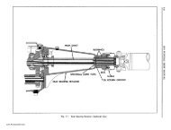
o~ 8.915-HEX NUT<br />
....<br />
O~ 7.377-BUSHING<br />
7.364-BRACKET ASSY.<br />
~ 7.377-BUSHING<br />
Fig. 3-14<br />
Upper Pivot Pin Assembly<br />
.,~- 7.345-SHOCK ABSORBER<br />
g<br />
~,.m_,","~G<br />
with chassis lubricant and install pin and lockwasher<br />
in control arm and knuckle support. See that pivot<br />
pin bolt head (with lockwasher) is turned up tigqtly<br />
against surface of control arm (50-55 lbs. ft. torque).<br />
4. Install pivot pin nut and lockwasher and tighten<br />
nut securely against surface of control arm (50-55<br />
lb. ft. torque). NOTE: Make visual inspection to see<br />
that bolt head and nut are turned up securely against<br />
metal of control arm to insure firm seating. If not,<br />
apply additional torque to seat parts properly.<br />
~ 8.915-HEX NUT<br />
Fig. 3- 13<br />
<strong>Front</strong> Shock Absorber and Mounting Parts<br />
4. Loosen clamp bolt and remove eccentric bushing<br />
from knuckle support.<br />
REPLACE<br />
1. Position seals over ends of upper control arms as<br />
shown in Fig. 3-15.<br />
2. Install new eccentric bushing in knuckle support<br />
so it is centralized (projects same amount both ends).<br />
3. Position knuckle support with bushing in forked<br />
end of upper control arm. Coat threads of pivot pin<br />
Fig. 3-15<br />
Seals Positioned for Assembly of Pivot Pin<br />
www.PontiacSafari.com