Front Suspension
Front Suspension
Front Suspension

Create successful ePaper yourself
Turn your PDF publications into a flip-book with our unique Google optimized e-Paper software.
3-12 1955 PONTIAC SHOP MANUAL<br />
b. Place pivot shaft with new rubber seals in position<br />
in control arm.<br />
c. After lubricating pivot shaft threads with chassis<br />
lubricant, start bushing on pivot shaft and into<br />
arm at same time. Tighten so bushing flange is firmly<br />
seated against control arm (326-380 lb. ft. torque).<br />
d. Center pivot shaft in control arm and install<br />
other bushing being sure threads index so there is no<br />
bind. Tighten so bushing flange is firmly s'eated<br />
against control arm (326-380 lb. ft. torque). Remove<br />
special spreader tool.<br />
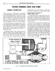
e. Check to see that distance between inner faces of<br />
shaft ends of control arm is correct (Fig. 3-20). Also<br />
check to see that pivot shaft is equalized in arm by<br />
measuring from bolt hole to arm at each end of shaft.<br />
Turn shaft in arm to centralize if distances from each<br />
bolt hole to arm are not equal. NOTE: Frictional<br />
drag of shaft in bushings should not exceed 12 lb. in.<br />
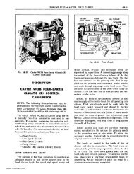
Fig. 3-21 Reaming Steering Knuckle<br />
with Reamer J-1324<br />
KING PIN AND BUSHINGS-REMOVE AND REPLACE<br />
REMOVE<br />
1. Jack up wheel under lower control arm and remove<br />
wheel and brake drum assembly.<br />
2. Remove backing plate without disconnecting<br />
brake hose. Place backing plate out of way' so as to<br />
avoid any strain on brake hose.<br />
3. Remove king pin lock pin (Fig. 3-2).<br />
Fig. 3-20 Correct Installation of Shaft<br />
in Upper Control Arm<br />
6. Position upper control arm and shaft on frame<br />
cross member and install two bolts and self-locking<br />
nuts. Tighten nuts to 80-85 lb. ft. torque. NOTE:<br />
Nuts must be installed and tightened by means of an<br />
extension inserted through access holes in front cross<br />
member.<br />
7. Complete installation by following procedure for<br />
installing upper pivot pin (page 3-7).<br />
8. Lubricate control arm shaft and upper pivot<br />
pin, replace wheel, lower car, and check front wheel<br />
alignment.<br />
4. Remove lower expansion plug under king pin by<br />
driving punch through upper expansion plug. If necessary,<br />
king pin can be driven up to remove upper<br />
expansion plug.<br />
5. Drive out king pin.<br />
6. Lift floating bushings from steering knuckle.<br />
REPLACE<br />
1. Using Expansion Plug Reamer J-1324 (Fig.<br />
3-21), clean up recesses in steering knuckle where<br />
metal was up set over expansion plugs.<br />
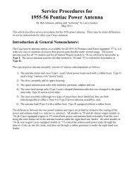
2. Lubricate new bushings and position in knuckle<br />
(Fig. 3-22). NOTE: King pin bushings require no<br />
special alignment when being installed in steering<br />
knuckle.<br />
www.PontiacSafari.com