You also want an ePaper? Increase the reach of your titles
YUMPU automatically turns print PDFs into web optimized ePapers that Google loves.
<strong>POWER</strong> <strong>STEERING</strong> 9-13<br />
drop and the flow control valve to open slightly, which<br />
in turn limits the pressure by allowing oil to return<br />
to the reservoir.<br />
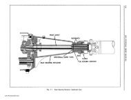
The schematic diagram in Fig. 9-26 shows the operation<br />
of the flow control valve when the car is being<br />
driven at high speed. The pump output at high speed<br />
exceeds 1.8 gallons per minute and opens the flow<br />
control valve to let oil return to the reservoir. This<br />
occurs during turns as well as in straight ahead<br />
driving.<br />
ADJUSTMENTS ON CAR<br />
Fig. 9-25<br />
Oil Flow in Pump With Low Car Speed<br />
and Full "U" Turn<br />
The schematic diagram in Fig. 9-24 is typical of<br />
pump operation when the car is being driven at low<br />
speed during a partial turn. The oil pressure cannot<br />
become high enough to open the relief valve, because<br />
the spool valve in the steering gear is still partially<br />
open allowing some oil to return to the pump reservoir.<br />
Also, due to the low pump speed, the oil flow is<br />
not great enough to open the flow control valve.<br />
The schematic diagram in Fig. 9-25 is typical of<br />
pump operation when the car is being driven in a full<br />
"U" turn at low speed with wheels cramped against<br />
stops. In this case maximum pump pressure is being<br />
applied to the piston to assist in the turn and the<br />
spool valve stops the flow of oil to the reservoir. The<br />
high oil pressure that develops opens the pressure<br />
relief valve. The restricted orifice between the outlet<br />
passage and the valve chamber causes the pressure to<br />
HIGH<br />
Before any adjustments are made to the power<br />
steering gear in an attempt to correct such conditions<br />
as shimmy, hard or loose steering, and road shocks,<br />
a careful check should be made to determine that<br />
front end alignment, shock absorbers, wheel balance<br />
and tire pressure are correct.<br />
There are three major adjustments of the power<br />
steering gear which can be made on the car:<br />
1. PITMAN SHAFT END PLAY ADJUST<br />
MENT.<br />
2. <strong>POWER</strong> RACK GUIDE ADJUSTMENT.<br />
3. <strong>PUMP</strong> BELT TENSION ADJUSTMENT.<br />
PITMAN SHAFT END PLA Y ADJUSTMENT<br />
1. Disconnect steering connecting rod from pitman<br />
arm by removing cotter pin and plug from connecting<br />
rod.<br />
2. Loosen four power rack guide cover bolts. Do<br />
not loosen two center bolts.<br />
3. Loosen pitman shaft adjusting screw lock nut<br />
and back off adjusting screw a few turns, using an<br />
offset screwdriver.<br />
4. With steering gear "on center", adjust pitman<br />
shaft thrust screw (Fig. 9-27) so that pull on steering<br />
wheel rim through a 3" arc using J-S44-A spring<br />
scale, is 1 to 1 Y4 Ibs. through center. Turning screw<br />
clockwise increases pull, counterclockwise decreases<br />
pull.<br />
5. Tighten nut while holding screw with offset<br />
screwdriver and recheck pull at rim of steering wheel.<br />
Fig. 9-26<br />
FLOW<br />
CONTROL VALVE<br />
Oil Flow in Pump With High Car Speed<br />
<strong>POWER</strong> RACK GUIDE ADJUSTMENT<br />
After pitman shaft end play has been adjusted,<br />
clearance between power rack gear and ball nut must<br />
be adjusted to prevent binding or excessive lash at<br />
this point.<br />
www.PontiacSafari.com