Contents / General Description / Carter WGD 2
Contents / General Description / Carter WGD 2
Contents / General Description / Carter WGD 2

Create successful ePaper yourself
Turn your PDF publications into a flip-book with our unique Google optimized e-Paper software.
6B-2 1955 PONTIAC SHOP MANUAL<br />
DESCRIPTION<br />
CARTER <strong>WGD</strong> DUAL CLIMATIC ®<br />
CONTROL* CARBURETOR<br />
NOTE: The following illustrations are used by<br />
permission of the copyright owner <strong>Carter</strong> Carburetor<br />
Corporation, St. Louis, Missouri. 6B-3<br />
through 6B-9, 6B-27, 6B-34, 6B-35, 6B-37.<br />
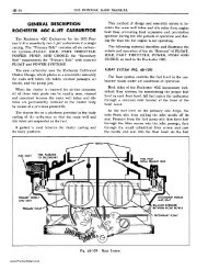
The <strong>Carter</strong> Model WGn dual carburetor combines<br />
design features of <strong>Carter</strong> carburetors used previously<br />
on Pontiac engines with several new features all in<br />
one easy-to-service assembly. A few of its new<br />
features are: Reduced over-all height, exhaust heated<br />
flange, simplified and accessible adjustments and a<br />
new compact Climatic Control choke.<br />
Five conventional circuits, as used in previous<br />
carburetors, are to be found in this unit. They are:<br />
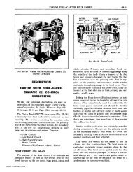
Fig. 68-2<br />
Cross-Section of Fuel Filter<br />
collected dirt and water to drain. In cases where<br />
excessive foreign material has collected in the filter<br />
and fuel starvation occurs the filter should be removed<br />
for cleaning. Before removing filter remove<br />
the drain plug and drain filter, then remove and<br />
agitate the filter in carburetor solvent or its<br />
equivalent. Direct an air stream through the outlet<br />
port of the filter to force dirt from the filter element<br />
through the inlet port or drain port. Rinse the filter<br />
in kerosene and again direct an air stream through<br />
the outlet port. Install drain plug and reinstall filter.<br />
CARBURETOR AIR CLEANER<br />
AND SILENCER<br />
Combined air cleaners and silencers are used on<br />
all models. These units filter air entering the<br />
carburetor to keep abrasive dust from being carried<br />
into the engine, and silence the induction system noise<br />
emanating from the carburetor.<br />
The air cleaner has an oil reservoir in its base<br />
so air entering the carburetor first strikes the oil<br />
in the cleaner reservoir, this coupled with the rapid<br />
change in direction of the air flow causes the heavier<br />
dust particles to be picked up by the oil. The high<br />
velocity of the air stream picks up some of the oil<br />
and carries it upward into the filter element through<br />
which the air next passes thus keeping the element<br />
continually washed and moistened with oil.<br />
Float Circuit<br />
Low-Speed Circuit<br />
High-Speed Circuit<br />
Pump Circuit<br />
Climatic Control (Choke) Circuit<br />
These circuits are described and illustrated schematically<br />
in the following text.<br />
Figures 6B-lO, 6B-11, and 6B-12 illustrate the<br />
passages as they actually appear to the carburetor<br />
mechanic.<br />
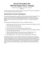
FLOAT CIRCUIT (FIG. 68-3J<br />
The purpose of the float circuit is to maintain a<br />
supply of fuel at the proper level in the bowl for<br />
use by the low-speed, high-speed and pump circuits.<br />
Setting the float to specifications assures an<br />
adequate supply of fuel in the bowl for all operating<br />
conditions. Float adjustment must be made with the<br />
bowl cover gasket removed and the bowl cover held<br />
inverted and level at eye height with the free weight<br />
of the float resting on the intake needle. Adjust the<br />
float by bending the float arm. To avoid placing unnecessary<br />
strain on the float do not grasp the float<br />
shell when bending the float arm.<br />
*"Climatic Control" Reg. U.S. Pat. Off.<br />
www.PontiacSafari.com