forced convection heat transfer from a circular cylinder embedded in ...
forced convection heat transfer from a circular cylinder embedded in ...
forced convection heat transfer from a circular cylinder embedded in ...

Create successful ePaper yourself
Turn your PDF publications into a flip-book with our unique Google optimized e-Paper software.
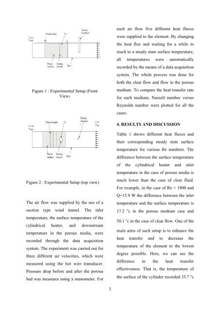
Figure 1 : Experimental Setup (Front<br />
View)<br />
each air flow five different <strong>heat</strong> fluxes<br />
were supplied to the element. By chang<strong>in</strong>g<br />
the <strong>heat</strong> flux and wait<strong>in</strong>g for a while to<br />
reach to a steady state surface temperature,<br />
all temperatures were automatically<br />
recorded by the means of a data acquisition<br />
system. The whole process was done for<br />
both the clear flow and flow <strong>in</strong> the porous<br />
medium. To compare the <strong>heat</strong> <strong>transfer</strong> rate<br />
for each medium, Nusselt number versus<br />
Reynolds number were plotted for all the<br />
cases.<br />
4. RESULTS AND DISCUSSION<br />
Figure 2 : Experimental Setup (top view)<br />
The air flow was supplied by the use of a<br />
suction type w<strong>in</strong>d tunnel. The <strong>in</strong>let<br />
temperature, the surface temperature of the<br />
cyl<strong>in</strong>drical <strong>heat</strong>er, and downstream<br />
temperature <strong>in</strong> the porous media, were<br />
recorded through the data acquisition<br />
system. The experiment was carried out for<br />
three different air velocities, which were<br />
measured us<strong>in</strong>g the hot wire transducer.<br />
Pressure drop before and after the porous<br />
bed was measures us<strong>in</strong>g a manometer. For<br />
Table 1 shows different <strong>heat</strong> fluxes and<br />
their correspond<strong>in</strong>g steady state surface<br />
temperature for various numbers. The<br />
difference between the surface temperature<br />
of the cyl<strong>in</strong>drical <strong>heat</strong>er and <strong>in</strong>let<br />
temperature <strong>in</strong> the case of porous media is<br />
much lower than the case of clear fluid.<br />
For example, <strong>in</strong> the case of Re = 1800 and<br />
Q=15.9 W the difference between the <strong>in</strong>let<br />
temperature and the surface temperature is<br />
17.2 ºc <strong>in</strong> the porous medium case and<br />
50.1 ºc <strong>in</strong> the case of clear flow. One of the<br />
ma<strong>in</strong> aims of such setup is to enhance the<br />
<strong>heat</strong> <strong>transfer</strong> and to decrease the<br />
temperature of the element to the lowest<br />
degree possible. Here, we can see the<br />
difference <strong>in</strong> the <strong>heat</strong> <strong>transfer</strong><br />
effectiveness. That is, the temperature of<br />
the surface of the <strong>cyl<strong>in</strong>der</strong> recorded 35.7 ºc<br />
3