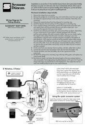
Wiring Diagram for Pickup Models: - Seymour Duncan
Wiring Diagram for Pickup Models: - Seymour Duncan
Wiring Diagram for Pickup Models: - Seymour Duncan

Create successful ePaper yourself
Turn your PDF publications into a flip-book with our unique Google optimized e-Paper software.
The installation of the Basslines Tone Circuit 3-band EQ system is a straight<strong>for</strong>ward process requiring minimal<br />
tools and reasonable proficiency in soldering and following wiring diagrams. If you are unsure of your soldering<br />
ability or unfamiliar with basic electronic wiring methods, it is advisable to employ the services of a competent tech.<br />
The standard control configuration comes prewired. This is done to simplify installation. However, several additional<br />
wiring configurations are shown in order to demonstrate other possibilities. By applying the basic hookup<br />
in<strong>for</strong>mation to other combinations of stacked or push-pull pots, further variations can be achieved. In this way it is<br />
easy to customize the control set-up to meet the needs or preferences of the individual player.<br />
<strong>Wiring</strong> <strong>Diagram</strong> <strong>for</strong><br />
<strong>Pickup</strong> <strong>Models</strong>:<br />
Tone Circuits TM<br />
2 & 3-Band Active EQ Preamps<br />
<strong>for</strong> Bass<br />
STC-2A, STC-2P<br />
STC-3A, STC-3P<br />
5427 hollister avenue, santa barbara, ca 93111<br />
tel 805.964.9610 fax 805.964.9749<br />
www.basslines.com<br />
The basic steps <strong>for</strong> installation include:<br />
Proper operation depends on proper hookup of all connections; observe color codes and wire locations carefully.<br />
1. Remove any old pots that will not be used in this new installation.<br />
2. Remove the two plastic connectors with the hookup wires and pots attached. Note that the connector<br />
housings have been color coded in order to facilitate returning each connector to its proper location after all<br />
hookup has been completed. Avoid excessive bending and flexing of the connections to the pots.<br />
3. Carefully install the new pots in the proper locations.<br />
4. If you are installing the Basslines EQ system in a bass containing passive pickups, it will be necessary to<br />
install a stereo output jack at this time. The stereo output jack provides a means of switching the battery power<br />
off automatically when the intrument cord is removed from the bass, thus prolonging the life of the battery.<br />
The jack is included with the passive version of the Tone Circuit. Refer to Fig. 3 <strong>for</strong> proper hook-up of the jack<br />
included with the system.<br />
5. Solder the remaining connections as indicated on the standard hookup diagram. You may notice that the red<br />
and black wires do not appear on the diagram. The red wire is +9V and is soldered to battery hot and insulated<br />
with shrink tubing or tape. The black wire which connects the shells of all the potentiometers is soldered to the<br />
ground connection of the jack. Battery black is connected to the ring terminal of the stereo output jack.<br />
6. Double check all of your connections, then re-install the two connectors in the circuit board making sure to return<br />
them to the proper location.<br />
7. Attach the preamp to the control cavity of your instrument using the Velcro strip provided. Be sure there are no<br />
components that are shorted to the sides or backs of the pots.<br />
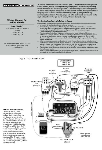
Fig. 1 STC-3A and STC-3P<br />
What’s the difference?<br />
The STC-3P and STC-2P are<br />
designed <strong>for</strong> use with passive<br />
pickups. The STC-3A and STC-2A<br />
are designed <strong>for</strong> use with active<br />
pickups. The main difference between<br />
the P-models and the A-models is the<br />
value of the blend control. The<br />
P-models use a 250k blend, and the<br />
A-models use a 100k blend. The 3P<br />
and 3A models are both 3-band tone<br />
circuits which, in addition to the<br />
master volume and blend controls,<br />
have midrange, bass, and treble (the<br />
bass and treble are combined on a<br />
stacked pot). The 2P and 2A models<br />
are both 2-band tone circuits, and do<br />
not have a midrange control---just bass<br />
and treble (stacked).
Fig. 2 STC-2A and STC-2P<br />
Slap Contour Adjustment<br />
The switchable slap contour is preset at the factory but it can<br />
be fine-tuned to suit individual taste. It is possible to preset the<br />
amount of bass boost or midrange cut by adjusting the<br />
trimpots located on the circuit board.<br />
Output Jack Hookup Detail<br />
Fig. 3<br />
We’re not just pickups anymore. <strong>Seymour</strong> <strong>Duncan</strong> also makes super cool stompboxes. And our sister company, D-TAR,<br />
is turning out some really hip products <strong>for</strong> serious acoustic guitarists (d-tar.com).<br />
P/N 501060-105 Rev. C<br />
Visit basslines.com <strong>for</strong> additional wiring diagrams.