Exercise 3 â UML modelling in ArcGIS
Exercise 3 â UML modelling in ArcGIS
Exercise 3 â UML modelling in ArcGIS

You also want an ePaper? Increase the reach of your titles
YUMPU automatically turns print PDFs into web optimized ePapers that Google loves.
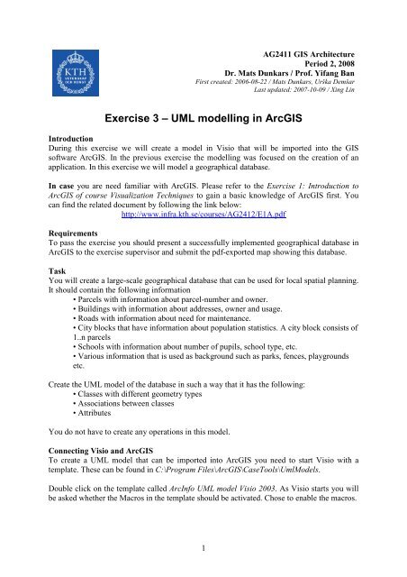
AG2411 GIS Architecture<br />
Period 2, 2008<br />
Dr. Mats Dunkars / Prof. Yifang Ban<br />
First created: 2006-08-22 / Mats Dunkars, Urška Demšar<br />
Last updated: 2007-10-09 / X<strong>in</strong>g L<strong>in</strong><br />
<strong>Exercise</strong> 3 – <strong>UML</strong> <strong>modell<strong>in</strong>g</strong> <strong>in</strong> <strong>ArcGIS</strong><br />
Introduction<br />
Dur<strong>in</strong>g this exercise we will create a model <strong>in</strong> Visio that will be imported <strong>in</strong>to the GIS<br />
software <strong>ArcGIS</strong>. In the previous exercise the <strong>modell<strong>in</strong>g</strong> was focused on the creation of an<br />
application. In this exercise we will model a geographical database.<br />
In case you are need familiar with <strong>ArcGIS</strong>. Please refer to the <strong>Exercise</strong> 1: Introduction to<br />
<strong>ArcGIS</strong> of course Visualization Techniques to ga<strong>in</strong> a basic knowledge of <strong>ArcGIS</strong> first. You<br />
can f<strong>in</strong>d the related document by follow<strong>in</strong>g the l<strong>in</strong>k below:<br />
http://www.<strong>in</strong>fra.kth.se/courses/AG2412/E1A.pdf<br />
Requirements<br />
To pass the exercise you should present a successfully implemented geographical database <strong>in</strong><br />
<strong>ArcGIS</strong> to the exercise supervisor and submit the pdf-exported map show<strong>in</strong>g this database.<br />
Task<br />
You will create a large-scale geographical database that can be used for local spatial plann<strong>in</strong>g.<br />
It should conta<strong>in</strong> the follow<strong>in</strong>g <strong>in</strong>formation<br />
• Parcels with <strong>in</strong>formation about parcel-number and owner.<br />
• Build<strong>in</strong>gs with <strong>in</strong>formation about addresses, owner and usage.<br />
• Roads with <strong>in</strong>formation about need for ma<strong>in</strong>tenance.<br />
• City blocks that have <strong>in</strong>formation about population statistics. A city block consists of<br />
1..n parcels<br />
• Schools with <strong>in</strong>formation about number of pupils, school type, etc.<br />
• Various <strong>in</strong>formation that is used as background such as parks, fences, playgrounds<br />
etc.<br />
Create the <strong>UML</strong> model of the database <strong>in</strong> such a way that it has the follow<strong>in</strong>g:<br />
• Classes with different geometry types<br />
• Associations between classes<br />
• Attributes<br />
You do not have to create any operations <strong>in</strong> this model.<br />
Connect<strong>in</strong>g Visio and <strong>ArcGIS</strong><br />
To create a <strong>UML</strong> model that can be imported <strong>in</strong>to <strong>ArcGIS</strong> you need to start Visio with a<br />
template. These can be found <strong>in</strong> C:\Program Files\<strong>ArcGIS</strong>\CaseTools\UmlModels.<br />
Double click on the template called ArcInfo <strong>UML</strong> model Visio 2003. As Visio starts you will<br />
be asked whether the Macros <strong>in</strong> the template should be activated. Chose to enable the macros.<br />
1
You may also get a w<strong>in</strong>dow say<strong>in</strong>g someth<strong>in</strong>g like: the security level is high and macros are<br />
not enabled. If this happens choose Tools – Macros – Security. Change the security level to<br />
low and then restart Visio from the <strong>ArcGIS</strong> template <strong>in</strong> the manner described above.<br />
When Visio has started you can look <strong>in</strong> the Model Explorer. Here you can f<strong>in</strong>d a new folder<br />
called ArcInfo Uml Model. In this folder you f<strong>in</strong>d other folders that conta<strong>in</strong> classes and<br />
<strong>in</strong>terfaces from the <strong>ArcGIS</strong> data model. These classes are used to get your own model<br />
connected to the <strong>ArcGIS</strong> data model. Further down you can also f<strong>in</strong>d a folder that conta<strong>in</strong>s<br />
types that have been def<strong>in</strong>ed <strong>in</strong> the <strong>ArcGIS</strong> data model.<br />
To create your own class diagram you start by add<strong>in</strong>g a package under Workspace and then<br />
add<strong>in</strong>g a new Static structure diagram <strong>in</strong> this package <strong>in</strong> the same way as we did <strong>in</strong> the<br />
previous exercise.<br />
You connect to the <strong>ArcGIS</strong> data model by <strong>in</strong>herit<strong>in</strong>g the functionality from one of the ESRI<br />
object classes. Here we will only consider two classes: “Feature” and “Object”. Object is a<br />
class with no geometry while “Feature” is a class that has geometry. A class that should have<br />
geometry should <strong>in</strong>herit from the “Feature” class and a class without geometry <strong>in</strong>herit from<br />
“Object”. Both classes can be found <strong>in</strong> the Model Explorer under ArcInfo Uml Model –<br />
Logical View – ESRI Classes.<br />
To create an object class for build<strong>in</strong>gs you first drag and drop the class “Feature” onto the<br />
diagram. Then you add your own new class for “Build<strong>in</strong>g” and a generalisation between the<br />
two classes to make sure that “Build<strong>in</strong>g” <strong>in</strong>herit the characteristics of “Feature”.<br />
To set the type of an attribute you have to use the data types provided by ESRI. For <strong>in</strong>stance,<br />
to set the data type of the Attribute “owner” on the “Build<strong>in</strong>g” class you choose the type<br />
“esriFieldTypeStr<strong>in</strong>g” rather than the ord<strong>in</strong>ary str<strong>in</strong>g type.<br />
The “Feature” class conta<strong>in</strong>s a geometry but it is not def<strong>in</strong>ed which k<strong>in</strong>d of geometry. This<br />
has to be def<strong>in</strong>ed as a “Tagged value” on the object class. This is what you are supposed to<br />
do:<br />
• Open the class w<strong>in</strong>dow for class “Build<strong>in</strong>g”<br />
• Choose the category “Tagged values”<br />
• Press the New button and call the new value “GeometryType”<br />
• Set the Value of “GeometryType”. You can choose between:<br />
“esriGeometryPolygon”, “esriGeometryPo<strong>in</strong>t” and “esriGeometryPolyl<strong>in</strong>e”.<br />
When you build your model, do not forget to occasionally save your work as the XML<br />
draw<strong>in</strong>g file!<br />
Export<strong>in</strong>g and check<strong>in</strong>g the model<br />
Import<strong>in</strong>g the model <strong>in</strong>to <strong>ArcGIS</strong> consist of three steps:<br />
1. export<strong>in</strong>g from Visio to an XML-file.<br />
2. Runn<strong>in</strong>g a semantics check on this file <strong>in</strong> Visio<br />
3. Import<strong>in</strong>g the XML-file to ArcCatalog<br />
2
As you develop your model it is a good idea to perform the two first steps regularly to f<strong>in</strong>d<br />
errors. These two steps are described here while the last step is described towards the end of<br />
the exercise.<br />
To be able to export your model as a XML file (attention, this is NOT the same as sav<strong>in</strong>g it as<br />
XML draw<strong>in</strong>g file, which you have been do<strong>in</strong>g so far), do the follow<strong>in</strong>g: first save your<br />
model, so you don’t lose it. Then go to Tools – Options – Advances – File Paths. In Add-ons<br />
add the follow<strong>in</strong>g path:<br />
C:\Program Files\Microsoft Office\Visio11\1033<br />
Close Visio and restart it from <strong>ArcGIS</strong> template (as before). Open the XML draw<strong>in</strong>g file that<br />
conta<strong>in</strong>s your model.<br />
For correct export to a XML file you need to have a file named uml.dtd located <strong>in</strong> the folder<br />
where you will store your XML file. This file can be empty. Make sure you have such a file <strong>in</strong><br />
the directory where you <strong>in</strong>tend to store your XML file. You can for example copy the uml.dtd<br />
file from the folder C:\Program Files\<strong>ArcGIS</strong>\CaseTools\Utilities to your directory at Z: disk.<br />
To export your model as a XML file you po<strong>in</strong>t at Tools – Add-Ons – ESRI XMI Export <strong>in</strong><br />
Visio. Give the XML file a proper name.<br />
To perform the semantic check you choose Tools – Macros – ESRI – Semantics_checker. A<br />
w<strong>in</strong>dow pops up where you can specify the file that is go<strong>in</strong>g to be checked. Browse to f<strong>in</strong>d the<br />
file created <strong>in</strong> the previous step. You should also mark that that you are go<strong>in</strong>g to check an<br />
XMI file. F<strong>in</strong>ally you press “Check” and hopefully there are no errors.<br />
To create a b<strong>in</strong>ary association you have to create an attribute where you can store the identity<br />
that is used for l<strong>in</strong>k<strong>in</strong>g. For <strong>in</strong>stance, to create an association between “build<strong>in</strong>gs” and<br />
“parcels” where one parcel can be associated with zero to many build<strong>in</strong>gs you first def<strong>in</strong>e an<br />
attribute <strong>in</strong> the “build<strong>in</strong>g” object class. Call this attribute “ParcelID” and give it the type<br />
“esriFieldTypeInteger”. In the table that will conta<strong>in</strong> the attributes for object class “build<strong>in</strong>g”<br />
there will be one column called “ParcelID”. Here the object identity of the parcel that a<br />
particular “build<strong>in</strong>g” belongs to, will be stored.<br />
Next you create the b<strong>in</strong>ary association. As you drag and drop the association onto the diagram<br />
you can see that the endpo<strong>in</strong>ts are given numbers, i.e. “end3” and “end4”. The part of the<br />
association that has the lower number should be set to po<strong>in</strong>t to the “Orig<strong>in</strong> class” and the other<br />
end should po<strong>in</strong>t at the “Foreign class”. In our example “Parcel” is the “Orig<strong>in</strong> class” while<br />
“Build<strong>in</strong>g” is the “Foreign class”.<br />
When the association is connected you should give it a name and def<strong>in</strong>e multiplicity. To<br />
def<strong>in</strong>e which columns that store the connection <strong>in</strong>formation you have to add two “Tagged<br />
values”. The first is called “Orig<strong>in</strong>PrimaryKey” and is given the value “OBJECTID”. The<br />
second is called “Orig<strong>in</strong>ForeignKey” and is given the value “ParcelID”.<br />
Here we have chosen “Parcel” as the orig<strong>in</strong> class s<strong>in</strong>ce one parcel can be connected to many<br />
build<strong>in</strong>gs. If we would have chosen “build<strong>in</strong>gs” as the orig<strong>in</strong> class we would have had to have<br />
an undef<strong>in</strong>ed number of columns to store the l<strong>in</strong>ks to different build<strong>in</strong>gs <strong>in</strong> the “Parcel” table.<br />
3
Create the rema<strong>in</strong><strong>in</strong>g object classes above and perform the consistency check from time to<br />
time. When the model is f<strong>in</strong>ished you can move on to the next step and import it <strong>in</strong>to <strong>ArcGIS</strong>.<br />
Import<strong>in</strong>g the XML file <strong>in</strong>to <strong>ArcGIS</strong><br />
To import your XML model you start ArcCatalog under Start – Programs - <strong>ArcGIS</strong> –<br />
ArcCatalog. ArcCatalog is the software used to manage databases and to connect to various<br />
geographical data sources.<br />
Before we can import our model we have to create a new “Personal geodatabase”. Right click<br />
<strong>in</strong> your home directory to create a new one.<br />
Next we have to f<strong>in</strong>d the tool that imports the XML – file. Chose Tools – Customize. A<br />
w<strong>in</strong>dow is shown called Customize. Click on Commands and chose Case Tools under<br />
Categories. Under Commands you know have a tool called Schema Wizard (see fig. 1). Drag<br />
and drop this command onto a toolbar. Close the customize w<strong>in</strong>dow.<br />
Fig. 1 The Schema Wizard can be found <strong>in</strong> the Customize w<strong>in</strong>dow.<br />
Next you click on the new symbol just added to the toolbar. After some time a w<strong>in</strong>dow called<br />
Schema Wizard is shown. In the firs w<strong>in</strong>dow you press Next. In the Second w<strong>in</strong>dow you chose<br />
Model stored <strong>in</strong> XMI file and then browse to f<strong>in</strong>d the XMI – file created <strong>in</strong> Visio. Click Next.<br />
In the next w<strong>in</strong>dow you can see the object classes that will be created. Click Next and <strong>in</strong> the<br />
last w<strong>in</strong>dow you click F<strong>in</strong>ish. F<strong>in</strong>ally you can double-click on the personal Geodatabase to<br />
see that your object classes have been created.<br />
Add data to your database <strong>in</strong> ArcMap. Choose Tools – ArcMAP. After a while ArcMap has<br />
started. In the first w<strong>in</strong>dow you chose to start us<strong>in</strong>g ArcMap with a new empty map. To<br />
connect to your database you choose Tools – Add data. Then you browse to f<strong>in</strong>d your<br />
database and select all the object-classes <strong>in</strong> the database that you would like to edit <strong>in</strong><br />
ArcMap. The object classes will be shown <strong>in</strong> the legend w<strong>in</strong>dow <strong>in</strong> ArcMap and now you can<br />
start edit<strong>in</strong>g, add<strong>in</strong>g new objects, etc. If you are not familiar with creat<strong>in</strong>g new objects <strong>in</strong><br />
ArcMap, use the Editor Menu and read about how to use it <strong>in</strong> Help under Contents – Edit<strong>in</strong>g<br />
<strong>in</strong> ArcMap – Creat<strong>in</strong>g New Features.<br />
F<strong>in</strong>ally you should produce a nice map (with appropriate colours, etc. like <strong>in</strong> <strong>Exercise</strong> 1:<br />
Introduction to <strong>ArcGIS</strong> of course Visualization Techniques) show<strong>in</strong>g your database<br />
implemented <strong>in</strong> ArcMap. Produce a pdf file of this map (see <strong>Exercise</strong> 1: Introduction to<br />
4
<strong>ArcGIS</strong> of course Visualization Techniques for how to do that) and submit it to the exercise<br />
supervisor.<br />
5