Si504 Any-Frequency 32 kHz – 100 MHz CMEMS ... - Silicon Labs
Si504 Any-Frequency 32 kHz – 100 MHz CMEMS ... - Silicon Labs
Si504 Any-Frequency 32 kHz – 100 MHz CMEMS ... - Silicon Labs

Create successful ePaper yourself
Turn your PDF publications into a flip-book with our unique Google optimized e-Paper software.
<strong>Si504</strong><br />
ANY-FREQUENCY <strong>32</strong> KH Z<strong>–</strong><strong>100</strong> MHZ<br />
<strong>CMEMS</strong> O SCILLATOR<br />
Features<br />
• Wide frequency range: <strong>32</strong> <strong>kHz</strong> to<br />
<strong>100</strong> <strong>MHz</strong><br />
•Contact <strong>Silicon</strong> <strong>Labs</strong> for<br />
frequencies above <strong>100</strong> <strong>MHz</strong><br />
• ±20/30/50 ppm frequency stability<br />
including 10-year aging<br />
• Single wire interface<br />
• LVCMOS output<br />
• Continuous supply voltage range:<br />
+1.71 V to +3.63 V<br />
• Low power<br />
Applications<br />
• Storage (SATA/SAS/PCIe)<br />
• General purpose processors<br />
• Industrial controllers<br />
• Embedded controllers<br />
• Motor control<br />
• Flow control<br />
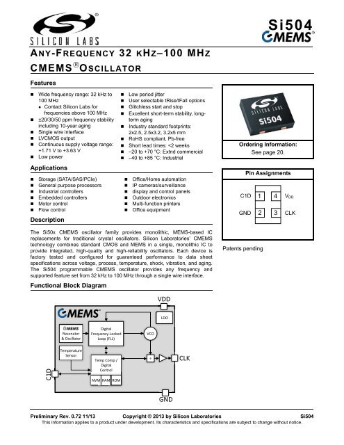
Description<br />
• Low period jitter<br />
• User selectable tRise/tFall options<br />
• Glitchless start and stop<br />
• Excellent short-term stability, longterm<br />
aging<br />
• Industry standard footprints:<br />
2x2.5, 2.5x3.2, 3.2x5 mm<br />
• RoHS compliant, Pb-free<br />
• Short lead times:
<strong>Si504</strong><br />
TABLE OF CONTENTS<br />
Section<br />
Page<br />
1. Electrical Specifications . . . . . . . . . . . . . . . . . . . . . . . . . . . . . . . . . . . . . . . . . . . . . . . . . . .3<br />
2. Typical Applications Circuit and AC Waveforms . . . . . . . . . . . . . . . . . . . . . . . . . . . . . . .9<br />
2.1. Application Circuit . . . . . . . . . . . . . . . . . . . . . . . . . . . . . . . . . . . . . . . . . . . . . . . . . . . .9<br />
2.2. AC Waveforms . . . . . . . . . . . . . . . . . . . . . . . . . . . . . . . . . . . . . . . . . . . . . . . . . . . . . .9<br />
3. Functional Description . . . . . . . . . . . . . . . . . . . . . . . . . . . . . . . . . . . . . . . . . . . . . . . . . . .11<br />
3.1. <strong>Si504</strong> Overview . . . . . . . . . . . . . . . . . . . . . . . . . . . . . . . . . . . . . . . . . . . . . . . . . . . . .11<br />
3.2. <strong>Frequency</strong> Adjustment . . . . . . . . . . . . . . . . . . . . . . . . . . . . . . . . . . . . . . . . . . . . . . .11<br />
3.3. Operational Modes (Run, Stop, Doze, Sleep) . . . . . . . . . . . . . . . . . . . . . . . . . . . . . .11<br />
3.4. Output Rise and Fall Settings . . . . . . . . . . . . . . . . . . . . . . . . . . . . . . . . . . . . . . . . . .11<br />
3.5. Single Wire C1 Interface . . . . . . . . . . . . . . . . . . . . . . . . . . . . . . . . . . . . . . . . . . . . . .12<br />
3.6. C1 Setup/Reset Sequence, Command/Byte Write<br />
Transaction and Issuing Commands . . . . . . . . . . . . . . . . . . . . . . . . . . . . . . . . . . . . .13<br />
3.7. Command State Diagram . . . . . . . . . . . . . . . . . . . . . . . . . . . . . . . . . . . . . . . . . . . . .15<br />
3.8. Command Byte Table . . . . . . . . . . . . . . . . . . . . . . . . . . . . . . . . . . . . . . . . . . . . . . . .16<br />
4. Pin Description . . . . . . . . . . . . . . . . . . . . . . . . . . . . . . . . . . . . . . . . . . . . . . . . . . . . . . . . . .19<br />
5. Ordering Guide . . . . . . . . . . . . . . . . . . . . . . . . . . . . . . . . . . . . . . . . . . . . . . . . . . . . . . . . . .20<br />
6. Package Dimensions and Land Patterns . . . . . . . . . . . . . . . . . . . . . . . . . . . . . . . . . . . . .21<br />
6.1. Package Outline: 3.2 x 5 mm 4-pin DFN . . . . . . . . . . . . . . . . . . . . . . . . . . . . . . . . . .21<br />
6.2. Package Outline: 2.5 x 3.2 mm 4-pin DFN . . . . . . . . . . . . . . . . . . . . . . . . . . . . . . . .21<br />
6.3. Package Outline: 2 x 2.5 mm 4-pin DFN . . . . . . . . . . . . . . . . . . . . . . . . . . . . . . . . . .21<br />
7. Top Markings . . . . . . . . . . . . . . . . . . . . . . . . . . . . . . . . . . . . . . . . . . . . . . . . . . . . . . . . . . .22<br />
7.1. 3.2 x 5 mm Top Marking . . . . . . . . . . . . . . . . . . . . . . . . . . . . . . . . . . . . . . . . . . . . . .22<br />
7.2. 3.2 x 5 mm Top Marking Explanation . . . . . . . . . . . . . . . . . . . . . . . . . . . . . . . . . . . .22<br />
7.3. 2.5 x 3.2 mm Top Marking . . . . . . . . . . . . . . . . . . . . . . . . . . . . . . . . . . . . . . . . . . . .23<br />
7.4. 2.5 x 3.2 mm Top Marking Explanation . . . . . . . . . . . . . . . . . . . . . . . . . . . . . . . . . . .23<br />
7.5. 2 x 2.5 mm Top Marking . . . . . . . . . . . . . . . . . . . . . . . . . . . . . . . . . . . . . . . . . . . . . .24<br />
7.6. 2 x 2.5 mm Top Marking Explanation . . . . . . . . . . . . . . . . . . . . . . . . . . . . . . . . . . . .24<br />
Document Change List . . . . . . . . . . . . . . . . . . . . . . . . . . . . . . . . . . . . . . . . . . . . . . . . . . . . .25<br />
Contact Information . . . . . . . . . . . . . . . . . . . . . . . . . . . . . . . . . . . . . . . . . . . . . . . . . . . . . . . .26<br />
2 Preliminary Rev. 0.72
<strong>Si504</strong><br />
1. Electrical Specifications<br />
Table 1. Recommended Operating Conditions<br />
V DD = 1.71 to 3.63 V, T A = <strong>–</strong>40 to 85 C unless otherwise indicated.<br />
Parameter Symbol Test Condition Min Typ Max Unit<br />
Supply Voltage 1 V DD 1.71 — 3.63 V<br />
Supply Current I DD1 C L =4 pF, 3.3 V DD , F CLK =1.0 <strong>MHz</strong>, low<br />
power option<br />
Static<br />
Supply Current<br />
Input High<br />
Voltage<br />
Input Low<br />
Voltage<br />
Internal Pull-up<br />
Resistor<br />
Operating<br />
Temperature<br />
I DD2<br />
C L =4 pF, 3.3 V DD , F CLK =<strong>100</strong> <strong>MHz</strong>, low<br />
power option<br />
C L =4 pF, 3.3 V DD , F CLK =1.0 <strong>MHz</strong>, low<br />
jitter option<br />
C L =4 pF, 3.3 V DD , F CLK =<strong>100</strong> <strong>MHz</strong>, low<br />
jitter option<br />
Mode=Stop, low power option<br />
F CLK =1 <strong>MHz</strong><br />
Mode=Stop, low jitter option<br />
F CLK =1 <strong>MHz</strong><br />
— 1.7 2.5 mA<br />
— 5.3 6.5 mA<br />
— 3.9 4.9 mA<br />
— 7.6 8.9 mA<br />
— 1.7 2.5 mA<br />
— 3.9 4.9 mA<br />
Mode=Doze — 670 890 A<br />
Mode=Sleep 2 — 0.3 1 A<br />
V IH C1D pin 0.7 x V DD — — V<br />
V IL C1D pin — — 0.3 x V DD V<br />
R I C1D pin 40 50 60 kΩ<br />
T A Extended commercial grade <strong>–</strong>20 — 70 C<br />
Notes:<br />
1. The supply voltage range is continuous from 1.71 to 3.63 V.<br />
2. C1D steady state = high.<br />
Industrial grade <strong>–</strong>40 — 85 C<br />
Preliminary Rev. 0.72 3
<strong>Si504</strong><br />
Table 2. Output Clock <strong>Frequency</strong> Characteristics 1<br />
V DD = 1.71 to 3.63 V, T A = <strong>–</strong>40 to 85 C unless otherwise indicated.<br />
Parameter Symbol Test Condition Min Typ Max Unit<br />
<strong>Frequency</strong><br />
F CLK 0.0<strong>32</strong> — <strong>100</strong> <strong>MHz</strong><br />
Range<br />
Step Size — 29.8 — ppb<br />
Clock Period T CLK 1/F CLK 31,250 — 10 ns<br />
Total Stability 2 F STAB <strong>–</strong>20 — +20 ppm<br />
<strong>–</strong>30 — +30 ppm<br />
<strong>–</strong>50 — +50 ppm<br />
Initial Accuracy F I Measured at 25 C at the time of<br />
shipping<br />
— ±2 — ppm<br />
Startup Time T SU From V DD crossing 1.71 V to first — 2.5 4 ms<br />
clock output.<br />
Resume Time T RUN From sleep mode — 2.5 5 ms<br />
From doze mode — 1.7 2.5 ms<br />
From stop mode — — 1.5 x T CLK + ns<br />
35<br />
Output Disable Time T D To sleep/doze mode, from output<br />
running<br />
— — 225 s<br />
<strong>Frequency</strong> Update<br />
Time<br />
Offset/Slew Rate<br />
Time<br />
T NEW_FREQ<br />
T SLEW<br />
To stop, from output running — — 1.5 x T CLK +<br />
35<br />
From end of NewFreq or<br />
OriginalFreq command to when<br />
new frequency has stabilized.<br />
From end of Offset Freq command<br />
to when offset/slewed frequency<br />
has stabilized.<br />
ns<br />
— — 5 ms<br />
— 600 — s<br />
Notes:<br />
1. Refer to Figures 2, 3, and 7 for timing diagrams and additional information.<br />
2. Orderable option. Stability budget consists of 10-year aging, initial tolerance, operating temperature range, rated power<br />
supply voltage change, load change, aging, shock, and vibration.<br />
4 Preliminary Rev. 0.72
<strong>Si504</strong><br />
Table 3. Single Wire Interface AC Characteristics*<br />
V DD = 1.71 to 3.63 V, T A = <strong>–</strong>40 to 85 C unless otherwise indicated.<br />
Parameter Symbol Test Condition Min Typ Max Unit<br />
Bit “0” Nominal<br />
Duration<br />
Bit “1” Nominal<br />
Duration<br />
T ZERO 0.45 — 5.5 s<br />
T ONE 2.5 x T ZERO — 16 s<br />
Bit “0” Tolerance T ZERO-TOL T ZERO x ± 10% 0.9 — 1.1<br />
Bit “1” Tolerance T ONE-TOL T ONE x ± 10% 0.9 — 1.1<br />
Transaction<br />
Reset/Abort Time<br />
Byte Write Within<br />
Command<br />
Sequence Spacing<br />
Between Command<br />
Sequence Spacing<br />
Initial/Reset<br />
Sequence to 1st<br />
Command<br />
Sleep Wake Up<br />
Pulse Width<br />
T RESET 30 — — s<br />
T CBI 50 — — s<br />
T CI 1 — — ms<br />
T RSC 1 — — ms<br />
T WUP 0.2 — — s<br />
*Note: Refer to Figures 2, 3, and 7 for timing diagrams and additional information.<br />
Preliminary Rev. 0.72 5
<strong>Si504</strong><br />
Table 4. Output Clock Levels and Symmetry<br />
V DD = 1.71 to 3.63 V, T A = <strong>–</strong>40 to 85 C unless otherwise indicated.<br />
Parameter Symbol Test Condition Min Typ Max Unit<br />
Output High Voltage V OH 1st ordering option code: A and H<br />
I OH =<strong>–</strong>4 mA<br />
Output Low Voltage V OL 1st ordering option code: A and H<br />
I OH =+4 mA<br />
Rise/Fall<br />
tRise /<br />
Time 1 tFall<br />
1 st ordering option code 2 : A and H<br />
Z 0 = 25 @ 3.3V<br />
1 st ordering option code: B and J<br />
Z 0 = 50 @ 3.3V<br />
1 st ordering option code: C and K<br />
Z 0 = 50 @ 2.5V<br />
1 st ordering option code: D and L<br />
Z 0 = 50 @ 1.8V<br />
1 st ordering option code: E and M<br />
Z 0 = 110 @ 3.3V<br />
1 st ordering option code: F and N<br />
Z 0 = 220 @ 3.3V<br />
1 st ordering option code: G and P<br />
Z 0 = 440 @ 3.3V<br />
Duty Cycle DC Drive strength selected such that<br />
tRise/tFall (20% to 80%)
<strong>Si504</strong><br />
Table 5. Output Clock Jitter and Phase Noise<br />
V DD = 1.71 to 3.63 V, T A = <strong>–</strong>40 to 85 C unless otherwise indicated.<br />
Parameter Symbol Test Condition Min Typ Max Unit<br />
Cycle-to-Cycle Jitter J CCPP <strong>100</strong> <strong>MHz</strong>, Low Jitter Option<br />
1 st ordering option code: H<br />
<strong>100</strong> <strong>MHz</strong>, Low Power Option<br />
1 st ordering option code: A<br />
Period Jitter J PRMS <strong>100</strong> <strong>MHz</strong>, Low Jitter Option<br />
1 st ordering option code: H<br />
<strong>100</strong> <strong>MHz</strong>, Low Power Option<br />
1 st ordering option code: A<br />
Period Jitter Pk-Pk J PPKPK Low Jitter Option<br />
10k samples<br />
1 st ordering option code: H<br />
Low Power Option<br />
10k samples<br />
1 st ordering option code: A<br />
Phase Jitter 1 75 <strong>MHz</strong><br />
F OFFSET =900 <strong>kHz</strong> to 7.5 <strong>MHz</strong><br />
Low Jitter Option<br />
1 st ordering option code: H<br />
75 <strong>MHz</strong><br />
F OFFSET =900 <strong>kHz</strong> to 7.5 <strong>MHz</strong><br />
Low Power Option<br />
1 st ordering option code: A<br />
— 14 25 ps pk-pk<br />
— 16 26 ps pk-pk<br />
— 1 1.6 ps rms<br />
— 1.3 1.9 ps rms<br />
— 9 13 ps pk-pk<br />
— 10 16 ps pk-pk<br />
— 1 1.3 ps rms<br />
— 2.5 3.2 ps rms<br />
Notes:<br />
1. Integrated phase jitter exceeds the requirements of some high-performance data communications systems. See<br />
AN783 for additional information.<br />
Preliminary Rev. 0.72 7
<strong>Si504</strong><br />
Table 6. Environmental Compliance and Package Information<br />
Parameter<br />
Condition<br />
Mechanical Shock MIL-STD-883, Method 2002, Cond B. (1,500 g)<br />
Mechanical Shock High g MIL-STD-883, Method 2002, Cond E. (10,000 g)<br />
Mechanical Vibration MIL-STD-883, Method 2007<br />
Solderability MIL-STD-883, Method 2003<br />
Temperature Cycle<br />
JESD22, Method A104<br />
Resistance to Solder Heat MIL-STD-883, Method 2036<br />
Contact Pads<br />
Gold over Nickel/Palladium<br />
Table 7. Thermal Characteristics<br />
Parameter Symbol Test Condition MAX Unit<br />
Thermal Impedance JA 3.2x5 mm, still air 187 °C/W<br />
2.5x3.2 mm, still air 239 °C/W<br />
2x2.5 mm, still air 241 °C/W<br />
Table 8. Absolute Maximum Ratings 1<br />
Parameter Symbol Rating Unit<br />
Maximum Operating Temperature T MAX 85 °C<br />
Storage Temperature T S <strong>–</strong>55 to +125 °C<br />
Supply Voltage V DD <strong>–</strong>0.5 to +3.8 V<br />
Input Voltage V IN <strong>–</strong>0.5 to V DD<br />
+0.3 V<br />
HBM ESD Sensitivity (JESD22-A114) HBM 2000 V<br />
CDM ESD Sensitivity CDM 500 V<br />
Soldering Temperature (Pb-free profile) 2 T PEAK 260 °C<br />
Soldering Time at T PEAK<br />
T P 20<strong>–</strong>40 s<br />
(PB-free profile) 2<br />
Junction Temperature T J 125 °C<br />
Notes:<br />
1. Stresses beyond those listed in this table may cause permanent damage to the device. Functional operation<br />
specification compliance is not implied at these conditions. Exposure to maximum rating conditions for extended<br />
periods may affect device reliability.<br />
2. The device is compliant with JEDEC J-STD-020.<br />
V<br />
8 Preliminary Rev. 0.72
2. Typical Applications Circuit and AC Waveforms<br />
2.1. Application Circuit<br />
<strong>Si504</strong><br />
MCU<br />
VDD<br />
~50K<br />
VDD<br />
OUTPUT<br />
DRIVER<br />
C1D 1<br />
<strong>Si504</strong><br />
4<br />
VDD<br />
0.1F<br />
GND 2 3<br />
CLK<br />
R S<br />
Z 0 = 50<br />
CLK<br />
Figure 1. <strong>Si504</strong> Application Circuit<br />
Note: Dotted line box is an optional component depending on tRise/tFall configuration option. See Table 4 for R S<br />
recommendations. See Section 5. "Ordering Guide” for configuration options.<br />
2.2. AC Waveforms<br />
VDD=1.71V<br />
Supply Voltage (VDD)<br />
CLK<br />
C1D<br />
C1D<br />
T SU<br />
Figure 2. Power-On Timing<br />
Notes:<br />
1. C1D steady state default polarity is set high (C1D=1) with an internal pull-up resistor. User may drive or pull C1D polarity<br />
low to change the C1D default steady state, however, the internal pull-up resistor will remain active.<br />
2. Refer to Table 2 and Table 3 for additional information.<br />
Preliminary Rev. 0.72 9
<strong>Si504</strong><br />
Sleep<br />
Command<br />
To<br />
Sleep<br />
Wake<br />
from<br />
Sleep<br />
C1D<br />
T D T WUP<br />
T RUN<br />
C1D<br />
Sleep<br />
Command<br />
CLK<br />
Figure 3. Sleep Timing<br />
Notes:<br />
1. C1D steady state default polarity is set high (C1D=1) with an internal pull-up resistor. User may drive or pull C1D polarity<br />
low to change the C1D default steady state; however, the internal pull-up resistor will remain active.<br />
2. Refer to Table 2 and Table 3 for additional information.<br />
10 Preliminary Rev. 0.72
<strong>Si504</strong><br />
3. Functional Description<br />
3.1. <strong>Si504</strong> Overview<br />
The <strong>Si504</strong> is a fully programmable <strong>CMEMS</strong> oscillator, capable of adjusting its base output frequency by 29.8 ppb<br />
frequency offset steps. The <strong>Si504</strong> supports all Si50x <strong>CMEMS</strong> oscillator functionality through a simple, single wire<br />
C1 interface. The C1 interface, its characteristics, and commands are described below. For further details,<br />
including C example code, please refer to application note AN752 which is available on the <strong>Silicon</strong> <strong>Labs</strong> website.<br />
The <strong>Si504</strong> starts up in the user’s ordered preconfiguration, as detailed in “5. Ordering Guide”, and also available at<br />
www.siliconlabs.com/cmems. Depending on the ordered options, some features may be limited such as <strong>Frequency</strong><br />
Stability, supported Temp Range, and Maximum Anticipated User <strong>Frequency</strong>. For example, a device that is ordered<br />
to support ± 50 ppm, -20 to 70 °C, and 80 <strong>MHz</strong> as the maximum required output frequency cannot support ± 30<br />
ppm or ± 20 ppm, -40 to 85 °C within spec, or any output frequency above 80 <strong>MHz</strong>.<br />
From initial power up, the <strong>Si504</strong> starts in Run mode with the output frequency and device configuration set to the<br />
ordered configuration. There is no option to initially power-up the <strong>Si504</strong> in any other mode than Run mode with the<br />
ordered configuration. Once the <strong>Si504</strong> has completed start-up, the user may reconfigure the <strong>Si504</strong> to any<br />
supported operating state, operating mode, configuration, or output frequency using C1 commands.<br />
Additional information on the Si50x <strong>CMEMS</strong> oscillator architecture and <strong>CMEMS</strong> technology is available in white<br />
papers posted on the <strong>Silicon</strong> <strong>Labs</strong> website at www.siliconlabs.com/cmems.<br />
3.2. <strong>Frequency</strong> Adjustment<br />
The <strong>Si504</strong> frequency adjustment is seamless and glitchless within the frequency offset (OffsetFreq command)<br />
range (±976.4566 ppm). However, if the user is adjusting the output frequency beyond this range (NewFreq<br />
command), for example, from <strong>32</strong>.768 <strong>kHz</strong> to 4 <strong>MHz</strong>, the <strong>Si504</strong> adjustment is not seamless since the device<br />
momentarily disables the output clock to recalibrate. The momentary blanking is glitchless, disabling and enabling<br />
the output clock with no runt pulses, imperfect or partial cycles.<br />
3.3. Operational Modes (Run, Stop, Doze, Sleep)<br />
The Si50x <strong>CMEMS</strong> series supports four operational output states. If enabled, the Si50x is in Run mode; thus, the<br />
clock is output and power is as specified in Table 1. The disable modes are Stop, Sleep, and Doze. Each of these<br />
states has a different power consumption profile, as specified in Table 1.<br />
3.3.1. Stop Mode<br />
The Si50x output in Stop mode is high-impedance, also known as High-Z (Hi-Z) or Tri-State. Stop mode disables<br />
the output driver, but the digital core and MEMS resonator remain enabled for fast transition to Run mode. The<br />
output is stopped and is held at High-Z after completing the last cycle glitch-free. No power saving measure is<br />
taken in Stop mode.<br />
3.3.2. Doze Mode<br />
The Si50x output in Doze mode is high-impedance, also known as High-Z (Hi-Z) or Tri-State. Doze mode disables<br />
the output driver, the VCO, and the MEMS resonator, but the digital core remains enabled. The output is stopped<br />
and is held at High-Z after completing the last cycle glitch-free.<br />
3.3.3. Sleep Mode<br />
The Si50x output in Sleep mode is high-impedance, also known as High-Z (Hi-Z) or Tri-State. Sleep mode disables<br />
power to all circuitry except for low-leakage circuitry that retains the last device configuration. The output is stopped<br />
and is held at High-Z after completing the last cycle glitch-free.<br />
3.4. Output Rise and Fall Settings<br />
The Si50x clock output is programmable. This enables reduction of electromagnetic interference (EMI) radiation<br />
from the clock output and also allows the Si50x to match the rise and fall of existing devices for easy replacement.<br />
The amount of EMI reduction from changing tRise/tFall settings is dependent on the output frequency, the<br />
harmonic of interest, and the board layout. Lab results using a 50 <strong>MHz</strong> FOUT and changing the clock tRise/tFall<br />
time from 0.7 ns to 8 ns show up to 14 dB of EMI reduction relative to the fundamental.<br />
Preliminary Rev. 0.72 11
<strong>Si504</strong><br />
The tRise/tFall feature also allows the Si50x to match competing devices’ rise and fall times. Crystal oscillator<br />
tRise/tFall behavior is largely dependent on the supply voltage. In crystal-based oscillators, a higher supply voltage<br />
will generally drive a more rapid tRise/tFall time. The Si50x configuration options match the tRise/tFall to the supply<br />
voltage according to the specifications in this data sheet. The Si50x also provides a specified tRise/tFall with a<br />
given supply voltage and a 50 trace impedance. See Table 4 for Si50x tRise/tFall specifications.<br />
3.5. Single Wire C1 Interface<br />
The <strong>Si504</strong> single wire C1 interface uses <strong>Silicon</strong> Laboratories’ patent-pending Transition Interval Code scheme<br />
which uses pulse widths to determine logic states.<br />
IMPORTANT NOTE:The C1 interface supports a beginning C1D polarity of either high (C1D=1) or low (C1D=0). C1D steady<br />
state is provisioned as high; however, users can force C1D steady state low; however, the internal pull-up<br />
resistor will remain active. Given the above conditions, diagrams below show both C1D polarity options.<br />
3.5.1. Single Wire C1 Interface Overview<br />
1. Transactions start from the steady state value of C1D. C1D default steady state is high (C1D=1), but<br />
customers may start C1D low (C1D=0) if they wish.<br />
2. The C1D steady state value can be changed by the user, but the <strong>Si504</strong> default steady state will remain high<br />
(C1D=1), and C1D must be driven low by the user circuit. <strong>Any</strong> steady state value change must be followed<br />
by a T RESET time during which no C1D changes are allowed.<br />
3. Transactions end with the same C1D value as that with which they started.<br />
4. Bit 0 and bit 1 are valid if they conform to the specified nominal time duration, T ZERO and T ONE , found in<br />
Table 3.<br />
5. The timing of bit 0 and bit 1 can vary from T ZERO and T ONE nominal duration by 10%. For example, if the<br />
nominal duration of bit 1 is 1 s then the longest duration is 1 s x 1.1 = 1.1 s, and the shortest duration is<br />
1 s x 0.9 = 0.9 s.<br />
6. The minimum nominal duration of bit 1 is 2.5 times the nominal duration of bit 0, with a maximum duration<br />
as specified in Table 3.<br />
7. If the C1D value is held steady for T RESET in the middle of a transaction, the transaction will abort and all<br />
the data will be discarded.<br />
12 Preliminary Rev. 0.72
3.6. C1 Setup/Reset Sequence, Command/Byte Write Transaction and Issuing<br />
Commands<br />
<strong>Si504</strong><br />
3.6.1. Setup/Reset Sequence<br />
The Setup/Reset Sequence is used to set up the C1 interface circuitry to receive commands. This transaction is<br />
mandatory after Power-Up and Wake-Up and optional after a command is reset using T RESET . The initial<br />
Command Reset Transaction is shown in Figure 4.<br />
T ZERO T ZERO T ONE T ONE<br />
C1D 0 0 0 0 1 0 0 1 0 0 1 1 0 0 1<br />
C1D 0 0 0 0 1 0 0 1 0 0 1 1 0 0 1<br />
Note: Refer to Table 2 and Table 3 for additional information.<br />
Figure 4. Setup/Reset Sequence<br />
To initialize the C1 interface after Power-Up, the following procedure should be applied:<br />
1. Apply V DD .<br />
2. Wait for T SU to complete.<br />
3. Apply the Setup/Reset Sequence.<br />
4. C1D must be steady state for >T RESET .<br />
5. Wait for T RSC to complete.<br />
6. The device is ready to accept user commands.<br />
To initialize the C1 interface after waking from sleep mode, the following procedure should be applied:<br />
1. C1D activity is not allowed when the device is in Sleep mode. <strong>Any</strong> C1D edge may wake the device.<br />
Therefore, the <strong>Si504</strong> does not accept user commands while in Sleep mode.<br />
2. Wake the device by applying a C1D steady state value change or T WUP C1D pulse. Please note that a C1D<br />
pulse narrower than the minimum T WUP specification may still wake the device.<br />
3. Wait for T RUN to complete.<br />
4. C1D must be steady state for >T RESET .<br />
5. Apply the Setup/Reset Sequence.<br />
6. Wait for T RSC to complete.<br />
7. The device is ready to accept user commands.<br />
3.6.2. Command/Byte Write Transaction<br />
The Command/Byte Write Transaction is used for the Command Byte and the Data Byte transfer during the<br />
command sequence. Each Command/Byte Write Transaction is a 15-bit bit field—a 7-bit preamble (always all 0s),<br />
and an 8-bit command/data field. The Command/Byte Write Transaction is shown in Figure 5. (Note that the LSB<br />
bit D0 is transferred first during transactions.) The Command Sequence Timing is shown in Figure 6.<br />
3.6.3. Issuing Commands<br />
1. Commands consist of one or more Commands/Byte Write Transactions.<br />
2. Each Command/Byte Write Transaction is a 15-bit bit field—a 7-bit preamble (always all 0s), and an 8-bit<br />
command/data field.<br />
3. Commands start with a Command Byte followed by 0 to 4 Data Bytes of the command argument.<br />
Preliminary Rev. 0.72 13
<strong>Si504</strong><br />
4. Command and data write transactions within user commands must be separated by at least T CBI time.<br />
5. Commands are processed after the last argument data byte is sent.<br />
6. Commands with data arguments can be reset and aborted by issuing an Setup/Reset Sequence in place of<br />
the data byte. Note that the transferred portion of the user command will be discarded.<br />
7. Transactions must be separated by at least T CI time.<br />
8. After Setup/Reset Sequence, wait at least T RSC time before issuing commands.<br />
C1D 0<br />
Beginning polarity = high<br />
0 0 0 0 0 0 D0 D1 D2<br />
D3 D4 D5 D6 D7<br />
PREAMBLE<br />
COMMAND WR/DATA WR<br />
C1D 0 0 0 0 0 0 0 D0 D1 D2<br />
D3 D4 D5 D6 D7<br />
Beginning polarity = low<br />
Figure 5. Command/Byte Write Transaction<br />
Command sequence<br />
T RSC<br />
T CBI<br />
T CBI<br />
T CI<br />
C1D<br />
Setup/<br />
Reset Seq<br />
Note 1<br />
Command<br />
Transaction<br />
Note 1<br />
Data<br />
Transaction<br />
Note 1<br />
Data<br />
Transaction<br />
Note 1<br />
Notes:<br />
1. The C1D value in shaded regions must remain stable for the action to complete. User may change C1D value to<br />
assert a C1D steady state change and reset the command.<br />
2. Refer to Table 2 and Table 3 for additional information.<br />
Figure 6. Command Sequence Timing<br />
14 Preliminary Rev. 0.72
3.7. Command State Diagram<br />
<strong>Si504</strong><br />
Figure 7 illustrates the valid operating <strong>Si504</strong> modes and transition commands. As illustrated, when the <strong>Si504</strong> is in<br />
the <strong>Frequency</strong> Setup state, it can only transition to Run mode. From Run mode, the <strong>Si504</strong> can transition to either<br />
Stop, Doze, Sleep, or back to <strong>Frequency</strong> Setup.<br />
VDD >= 1.71V<br />
Power Off<br />
NewFreq |<br />
OrderedFreq<br />
NewFreq |<br />
OrderedFreq<br />
Stop<br />
Power Up Freq Setup Run Mode<br />
Sleep<br />
Doze<br />
Run<br />
Stop Mode<br />
Sleep<br />
Doze<br />
C1D pulse > T WUP<br />
Sleep Mode<br />
Run<br />
Doze Mode<br />
Sleep<br />
NewFreq |<br />
OrderedFreq<br />
Notes:<br />
1. The device can receive C1 commands while it is in Run, Stop, or Doze modes. The device cannot receive C1<br />
command while in Sleep mode.<br />
2. Refer to Table 2 and Table 3 for additional information<br />
Figure 7. Command State Diagram<br />
Preliminary Rev. 0.72 15
<strong>Si504</strong><br />
3.8. Command Byte Table<br />
Table 9. Command Bytes<br />
Command Byte Name # Data Byte<br />
Arguments<br />
Description<br />
0x50 Run 0 Run Command.<br />
Transitions the <strong>Si504</strong> from any powered<br />
down state to Run mode. The <strong>Si504</strong><br />
returns to Run mode in its last configuration<br />
including base frequency, frequency<br />
offsets, and other configurable options.<br />
0x18 Stop 0 Stop Command.<br />
The output is stopped and is held at<br />
Hi-Z/Tri-State after completing the last<br />
cycle glitch-free. No power saving measure<br />
is taken.<br />
0x20 Doze 0 Doze Command.<br />
The output is stopped and is held at<br />
Hi-Z/Tri-State after completing the last<br />
cycle glitch-free. Power savings measures<br />
are enabled.<br />
0x30 Sleep 0 Sleep Command.<br />
The output is stopped and is held at<br />
Hi-Z/Tri-State after completing the last<br />
cycle glitch-free. Power is discontinued<br />
to all circuitry except for low-leakage circuitry<br />
which retains the last device configuration.<br />
0x0C NewFreq 4 (floating point <strong>32</strong>-bit<br />
IEEE-754 number in<br />
Hz, MSB first)<br />
New <strong>Frequency</strong> Command.<br />
NewFreq sets a new base frequency for<br />
the <strong>Si504</strong>. If the <strong>Si504</strong> is in Run mode,<br />
the output clock will stop glitch-free, and<br />
then restart at the new base frequency<br />
within<br />
T NEW_FREQ from the end of the command<br />
sequence. If the <strong>Si504</strong> is in Stop or<br />
Doze mode, the new base frequency is<br />
stored and applied when the device is<br />
brought out of Stop or Doze mode. <strong>Any</strong><br />
new base frequency may be overwritten<br />
while the device is in Stop or Doze<br />
mode. The last programmed new base<br />
frequency will be applied. The output<br />
clock does not glitch during its transition<br />
to the new base frequency. Please note<br />
that frequency offsets are cleared.<br />
16 Preliminary Rev. 0.72
<strong>Si504</strong><br />
Table 9. Command Bytes (Continued)<br />
Command Byte Name # Data Byte<br />
Arguments<br />
Description<br />
0x10 OriginalFreq 0 Ordered Configuration <strong>Frequency</strong>.<br />
OrderedFreq returns the <strong>Si504</strong> to its<br />
original ordered frequency and configuration.<br />
If the <strong>Si504</strong> is in Run mode, the<br />
output clock will stop glitch-free, and<br />
then restart at the ordered frequency<br />
within T NEW_FREQ from the end of the<br />
command sequence. If the <strong>Si504</strong> is in<br />
Stop or Doze mode, the command is<br />
stored and applied when the device is<br />
brought out of Stop or Doze mode. The<br />
output clock does not glitch during its<br />
transition. Please note that all pre-existing<br />
frequency offsets are cleared.<br />
0x3A OffsetFreq 2<br />
(signed integer MSB<br />
first)<br />
Offset <strong>Frequency</strong> Bytes.<br />
The <strong>Si504</strong> slews to the offset frequency<br />
from the base frequency specified by<br />
OffsetFreq. The offset frequency is in<br />
increments of 29.8 ppb (or 2 -25 ). <strong>Frequency</strong><br />
offset is an absolute frequency<br />
shift and is not a cumulative frequency<br />
shift. Stated differently, if there is an<br />
existing 1 ppm offset and the user<br />
requires a 2 ppm offset, the OffsetFreq<br />
command should program its value as<br />
2 ppm offset. The original 1 ppm offset<br />
will be overwritten. When in Run mode,<br />
the offset frequency will be settled on the<br />
output as specified by T SLEW . When in<br />
Stop or Doze mode, offset will be applied<br />
next time the part enters Run mode.<br />
Preliminary Rev. 0.72 17
<strong>Si504</strong><br />
Table 9. Command Bytes (Continued)<br />
Command Byte Name # Data Byte<br />
Arguments<br />
Description<br />
0x41 DrvStrength 1 Drive Strength Configuration<br />
Command.<br />
The output driver strength is selectable<br />
as specified in Table 4.<br />
Changing the output driver strength<br />
while running may cause glitches.<br />
Code<br />
Normalized<br />
Output<br />
Approximate<br />
tRise/tFall<br />
with V DD<br />
0x0 1x 8 ns (3.3V)<br />
0x1 2x 5 ns (3.3V)<br />
0x2 4x 3 ns (3.3V)<br />
0x3 8x 1.3 ns (3.3V)<br />
0x4 9x 1.3 ns (2.5V)<br />
0x5 10x 1.3 ns (1.8V)<br />
0x6 11x 1.3 ns (1.8V)<br />
0x7 18x 0.7 ns (3.3V)<br />
0x49 PwrJitter 1 Power and Jitter Configuration<br />
Command.<br />
The PwrJitter command transitions the<br />
device between low power or low jitter<br />
modes. The PwrJitter command may be<br />
written when the <strong>Si504</strong> is in Run, Stop,<br />
or Doze mode, but does not take effect<br />
until the <strong>Si504</strong> moves from one mode to<br />
another, thus passing through the <strong>Frequency</strong><br />
Setup state illustrated in Figure<br />
12. This includes issuing the Run command<br />
while the <strong>Si504</strong> is in Run mode.<br />
Code<br />
0x0<br />
0x1<br />
Command<br />
Low Power<br />
Mode<br />
Low Jitter<br />
Mode<br />
0x00 No Op 0 No Operation.<br />
18 Preliminary Rev. 0.72
<strong>Si504</strong><br />
4. Pin Description<br />
C1D<br />
1<br />
4<br />
V DD<br />
GND<br />
2<br />
3<br />
CLK<br />
<strong>Si504</strong><br />
Figure 8. <strong>Si504</strong> Pinout<br />
Table 10. Pin Descriptions<br />
Pin Name Function<br />
1 C1D Command Data Input Pin.<br />
C1D is the input to the single wire interface.<br />
2 GND Ground.<br />
3 CLK Output clock.<br />
4 V DD Power Supply Pin.<br />
Bypass with a 0.1 F capacitor placed as close to the V DD pin as possible.<br />
Preliminary Rev. 0.72 19
<strong>Si504</strong><br />
5. Ordering Guide<br />
The Si50x family of <strong>CMEMS</strong> oscillators are highly configurable. Each orderable part number must be specified<br />
according to the guidelines below. Each customized part’s performance is guaranteed to operate within the data<br />
sheet specifications. An online configuration and ordering tool is available at www.siliconlabs.com/cmems.<br />
VDD<br />
Jittervs TYP<br />
Power T R /T F<br />
A 1.73.6<br />
0.7ns 1<br />
B 3.3V 1.3ns 2<br />
C 2.5V 1.3ns 2<br />
Low<br />
D 1.8V 1.3ns 2<br />
Power<br />
E 1.73.6 3ns 3<br />
F 1.73.6 5ns 3<br />
G 1.73.6 8ns 3<br />
H 1.73.6<br />
0.7ns 1<br />
J 3.3V 1.3ns 2<br />
K 2.5V 1.3ns 2<br />
Low<br />
L 1.8V 1.3ns 2<br />
Jitter<br />
M 1.73.6 3ns 3<br />
N 1.73.6 5ns 3<br />
P 1.73.6 8ns 3<br />
A<br />
Internal<br />
PullResistor<br />
PullUponly<br />
A<br />
B<br />
504only 5<br />
Maximum F OUT<br />
0.0<strong>32</strong><strong>–</strong> 80<strong>MHz</strong><br />
0.0<strong>32</strong><strong>–</strong> <strong>100</strong><strong>MHz</strong><br />
504 J C A B D A G<br />
Revision<br />
Package<br />
Dimension<br />
B 3.2x5mm 6<br />
C 2.5x3.2mm<br />
D 2x2.5mm<br />
F<br />
G<br />
R<br />
R<br />
Temp<br />
Range<br />
20to70°C<br />
40to85°C<br />
Reel<br />
Reel<br />
CutTape<br />
OPN<br />
Prefix<br />
Description<br />
501 Singlefrequency<br />
502 Dual frequency<br />
503 Quadfrequency<br />
504 <strong>Any</strong>frequency<br />
Ppm<br />
A ±50<br />
B ±30<br />
C ±20<br />
<strong>Frequency</strong><br />
Code<br />
xxxxxx<br />
Description<br />
6digitcodefrom<strong>Silicon</strong><strong>Labs</strong><br />
Note:<br />
1. Series termination resistor (R S ) is recommended for this configuration. See Table 4 and Section 2.<br />
2. Series termination resistor is not needed for this configuration. Output impedance is 50 Ω for the indicated supply<br />
condition.<br />
3. Series termination resistor is not needed for this configuration. Reduced EMI setting.<br />
4. Please note that the maximum anticipated frequency has no lower frequency limit. A device can either be<br />
configured to support from <strong>32</strong> <strong>kHz</strong> up to 80 <strong>MHz</strong> or from <strong>32</strong> <strong>kHz</strong> up to <strong>100</strong> <strong>MHz</strong>.<br />
5. <strong>Silicon</strong> <strong>Labs</strong> 3.2 x 5 mm package is delivered as 3.2 x 4 mm and accommodates the industry-standard 3.2 x 5 mm<br />
footprint.<br />
Figure 9. <strong>Si504</strong> Part Number Syntax<br />
20 Preliminary Rev. 0.72
<strong>Si504</strong><br />
6. Package Dimensions and Land Patterns<br />
6.1. Package Outline: 3.2 x 5 mm 4-pin DFN<br />
4.00±0.15<br />
#4 #3 2.54<br />
3.20±0.15 1.20<br />
0.94<br />
2.20<br />
0. 90 Max<br />
#1 #2<br />
1.34 1.20<br />
1.60<br />
(Top View)<br />
Note: The 3.2 x 5 mm package is delivered as a 3.2 x 4 mm package and is drop-in compatible to<br />
industry-standard 3.2 x 5 landing patterns.<br />
Figure 10. 3.2 x 5 mm 4-pin DFN<br />
6.2. Package Outline: 2.5 x 3.2 mm 4-pin DFN<br />
1.50<br />
3.20±0.15 2.20<br />
#4 #3<br />
2.50±0.15<br />
0.90<br />
0.70<br />
1.90<br />
#1 #2<br />
1.20 0.90<br />
1.20<br />
0.90 Max<br />
(Top View)<br />
1.40<br />
6.3. Package Outline: 2 x 2.5 mm 4-pin DFN<br />
Figure 11. 2.5 x 3.2 mm 4-pin DFN<br />
2.50±0.15<br />
#4 #3<br />
1.90<br />
2.00±0.15<br />
0.70<br />
0.55<br />
1.50<br />
0.90 Max<br />
#1 #2<br />
1.00 0.65<br />
(Top View)<br />
Figure 12. 2 x 2.5 mm 4-pin DFN<br />
1.10<br />
1.00<br />
Preliminary Rev. 0.72 21
<strong>Si504</strong><br />
7. Top Markings<br />
7.1. 3.2 x 5 mm Top Marking<br />
7.2. 3.2 x 5 mm Top Marking Explanation<br />
Mark Method:<br />
Font Size:<br />
Laser<br />
0.60 mm<br />
Right-Justified<br />
Line 1 Marking: TTTTTT=Trace Code Manufacturing Code from the<br />
Assembly Purchase Order form.<br />
Line 2 Marking<br />
Circle=0.5 mm<br />
Diameter<br />
Left-Justified<br />
YY=Year<br />
WW=Work Week<br />
Pin 1 Indicator<br />
Assigned by the Assembly House.<br />
Corresponds to the year and work<br />
week of the build date.<br />
22 Preliminary Rev. 0.72
<strong>Si504</strong><br />
7.3. 2.5 x 3.2 mm Top Marking<br />
7.4. 2.5 x 3.2 mm Top Marking Explanation<br />
Mark Method:<br />
Font Size:<br />
Laser<br />
0.50 mm<br />
Right-Justified<br />
Line 1 Marking: TTTTT=Trace Code Manufacturing Code from the<br />
Assembly Purchase Order form.<br />
Line 2 Marking:<br />
Circle=0.3 mm Diameter<br />
Left-Justified<br />
Y=Year<br />
WW=Work Week<br />
Pin 1 Indicator<br />
Assigned by the Assembly House.<br />
Corresponds to the year and work<br />
week of the build date.<br />
Preliminary Rev. 0.72 23
<strong>Si504</strong><br />
7.5. 2 x 2.5 mm Top Marking<br />
7.6. 2 x 2.5 mm Top Marking Explanation<br />
Mark Method:<br />
Font Size:<br />
Laser<br />
0.50 mm<br />
Right-Justified<br />
Line 1 Marking: TTTT=Trace Code Manufacturing Code from the<br />
Assembly Purchase Order form.<br />
Line 2 Marking:<br />
Circle=0.3 mm Diameter<br />
Left-Justified<br />
Y=Year<br />
WW=Work Week<br />
Pin 1 Indicator<br />
Assigned by the Assembly House.<br />
Corresponds to the year and work<br />
week of the build date.<br />
24 Preliminary Rev. 0.72
<strong>Si504</strong><br />
DOCUMENT CHANGE LIST<br />
Revision 0.21 to Revision 0.4<br />
• Modified Title page.<br />
• Modified Table 1.<br />
• Modified Table 2.<br />
• Modified Table 3.<br />
• Modified Table 4.<br />
• Modified Table 5.<br />
• Modified Table 6.<br />
• Modified Table 7.<br />
• Modified Table 8.<br />
• Modified Section 2.<br />
• Modified Section 3.<br />
• Modified Section 4.<br />
• Modified Section 5.<br />
• Modified Section 6.<br />
• Modified Section 7.<br />
Revision 0.4 to Revision 0.41<br />
• Modified Table 5.<br />
Revision 0.41 to Revision 0.7<br />
• Revised supported frequency range<br />
• Added MIN/MAX figures to all relevant tables<br />
Revision 0.7 to Revision 0.71<br />
• Revised Table 4<br />
• Revised Section 6<br />
Revision 0.71 to Revision 0.72<br />
• Revised Table 2.<br />
• Revised Table 4.<br />
• Revised Table 6.<br />
• Modified Section 2.<br />
• Modified Section 3.<br />
• Modified Section 5.<br />
Preliminary Rev. 0.72 25
<strong>Si504</strong><br />
CONTACT INFORMATION<br />
<strong>Silicon</strong> Laboratories Inc.<br />
400 West Cesar Chavez<br />
Austin, TX 78701<br />
Tel: 1+(512) 416-8500<br />
Fax: 1+(512) 416-9669<br />
Toll Free: 1+(877) 444-30<strong>32</strong><br />
Please visit the <strong>Silicon</strong> <strong>Labs</strong> Technical Support web page:<br />
https://www.siliconlabs.com/support/pages/contacttechnicalsupport.aspx<br />
and register to submit a technical support request.<br />
Patent Notice<br />
<strong>Silicon</strong> <strong>Labs</strong> invests in research and development to help our customers differentiate in the market with innovative low-power, small size, analogintensive<br />
mixed-signal solutions. <strong>Silicon</strong> <strong>Labs</strong>' extensive patent portfolio is a testament to our unique approach and world-class engineering team<br />
The information in this document is believed to be accurate in all respects at the time of publication but is subject to change without notice.<br />
<strong>Silicon</strong> Laboratories assumes no responsibility for errors and omissions, and disclaims responsibility for any consequences resulting from<br />
the use of information included herein. Additionally, <strong>Silicon</strong> Laboratories assumes no responsibility for the functioning of undescribed features<br />
or parameters. <strong>Silicon</strong> Laboratories reserves the right to make changes without further notice. <strong>Silicon</strong> Laboratories makes no warranty, representation<br />
or guarantee regarding the suitability of its products for any particular purpose, nor does <strong>Silicon</strong> Laboratories assume any liability<br />
arising out of the application or use of any product or circuit, and specifically disclaims any and all liability, including without limitation consequential<br />
or incidental damages. <strong>Silicon</strong> Laboratories products are not designed, intended, or authorized for use in applications intended to<br />
support or sustain life, or for any other application in which the failure of the <strong>Silicon</strong> Laboratories product could create a situation where personal<br />
injury or death may occur. Should Buyer purchase or use <strong>Silicon</strong> Laboratories products for any such unintended or unauthorized application,<br />
Buyer shall indemnify and hold <strong>Silicon</strong> Laboratories harmless against all claims and damages.<br />
<strong>Silicon</strong> Laboratories and <strong>Silicon</strong> <strong>Labs</strong> are trademarks of <strong>Silicon</strong> Laboratories Inc.<br />
Other products or brandnames mentioned herein are trademarks or registered trademarks of their respective holders.<br />
26 Preliminary Rev. 0.72