

Sloan ECOS Single- and Dual-Flush Flushometers | Installation ...
Sloan ECOS Single- and Dual-Flush Flushometers | Installation ...
Sloan ECOS Single- and Dual-Flush Flushometers | Installation ...

You also want an ePaper? Increase the reach of your titles
YUMPU automatically turns print PDFs into web optimized ePapers that Google loves.
1<br />
Code No. 0816721<br />
Rev. 4 (12/11)<br />
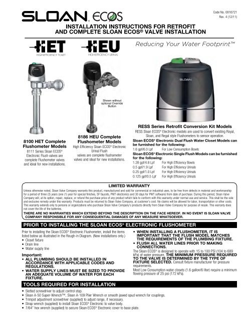
INSTALLATION INSTRUCTIONS FOR RETROFIT<br />
AND COMPLETE SLOAN <strong>ECOS</strong> ® VALVE INSTALLATION<br />
2<br />
Reducing Your Water Footprint<br />
Shown without<br />
optional Override<br />
Button<br />
8100 HET Complete<br />
<strong>Flush</strong>ometer Models<br />
8111 Series <strong>Sloan</strong> <strong>ECOS</strong> ®<br />
Electronic <strong>Flush</strong> valves are<br />
complete <strong>Flush</strong>ometer valves<br />
<strong>and</strong> ideal for new installations.<br />
8186 HEU Complete<br />
<strong>Flush</strong>ometer Models<br />
High Efficiency <strong>Sloan</strong> <strong>ECOS</strong> ® Electronic<br />
Urinal <strong>Flush</strong><br />
valves are complete flushometer<br />
valves <strong>and</strong> ideal for new installations.<br />
RESS Series Retrofit Conversion Kit Models<br />
RESS <strong>Sloan</strong> <strong>ECOS</strong> ® Electronic models are used to convert existing Royal,<br />
<strong>Sloan</strong>, <strong>and</strong> Regal style <strong>Flush</strong>ometers to sensor operation.<br />
<strong>Sloan</strong> <strong>ECOS</strong> ® Electronic <strong>Dual</strong> <strong>Flush</strong> Water Closet Models can<br />
be furnished for the following:<br />
1.6 gpf/6.0 Lpf For Low Consumption Bowls<br />
<strong>Sloan</strong> <strong>ECOS</strong> ® Electronic <strong>Single</strong> <strong>Flush</strong> Models can be furnished<br />
for the following:<br />
1.28 gpf/4.8 Lpf For High Efficiency Bowls<br />
0.5 gpf/1.9 Lpf For High Efficiency Urinals<br />
0.25 gpf/1.0 Lpf For High Efficiency Urinals<br />
0.125 gpf/0.5 Lpf For High Efficiency Urinals<br />
LIMITED WARRANTY<br />
Unless otherwise noted, <strong>Sloan</strong> Valve Company warrants this product, manufactured <strong>and</strong> sold for commercial or industrial uses, to be free from defects in material <strong>and</strong> workmanship<br />
for a period of three (3) years (one (1) year for special finishes, SF faucets, PWT electronics <strong>and</strong> 30 days for PWT software) from date of purchase. During this period, <strong>Sloan</strong> Valve<br />
Company will, at its option, repair, replace, or refund the purchase price of any product which fails to conform with this warranty under normal use <strong>and</strong> service. This shall be the sole<br />
<strong>and</strong> exclusive remedy under this warranty. Products must be returned to <strong>Sloan</strong> Valve Company, at customer’s cost. No claims will be allowed for labor, transportation or other costs.<br />
This warranty extends only to persons or organizations who purchase <strong>Sloan</strong> Valve Company’s products directly from <strong>Sloan</strong> Valve Company for purpose of resale. This warranty does<br />
not cover the life of the batteries.<br />
THERE ARE NO WARRANTIES WHICH EXTEND BEYOND THE DESCRIPTION ON THE FACE HEREOF. IN NO EVENT IS SLOAN VALVE<br />
COMPANY RESPONSIBLE FOR ANY CONSEQUENTIAL DAMAGES OF ANY MEASURE WHATSOEVER.<br />
PRIOR TO INSTALLING THE SLOAN <strong>ECOS</strong> ® ELECTRONIC FLUSHOMETER<br />
Prior to installing the <strong>Sloan</strong> <strong>ECOS</strong> ® Electronic <strong>Flush</strong>ometer, install the items<br />
listed below as illustrated in the Rough-in Diagram. (New installations only.)<br />
• Closet fixture<br />
• Drain line<br />
• Water supply line<br />
Important:<br />
• ALL PLUMBING SHOULD BE INSTALLED IN<br />
ACCORDANCE WITH APPLICABLE CODES AND<br />
REGULATIONS.<br />
• WATER SUPPLY LINES MUST BE SIZED TO PROVIDE<br />
AN ADEQUATE VOLUME OF WATER FOR EACH<br />
FIXTURE.<br />
TOOLS REQUIRED FOR INSTALLATION<br />
• Slotted screwdriver to adjust control stop.<br />
• <strong>Sloan</strong> A-50 Super-Wrench, <strong>Sloan</strong> A-109 Plier Wrench or smooth jawed spud wrench for couplings.<br />
• Trimpot adjustment screwdriver (supplied) to adjust range, if necessary.<br />
• Strap wrench (supplied) to install <strong>Sloan</strong> <strong>ECOS</strong> ® Electronic to valve body.<br />
• 7/64” hex wrench (supplied) to secure <strong>Sloan</strong> <strong>ECOS</strong> ® Electronic cover to base plate.<br />
• WHEN INSTALLING A FLUSHOMETER, IT IS<br />
IMPORTANT THAT THE FLUSH MODEL MATCHES<br />
THE REQUIREMENTS OF THE PLUMBING FIXTURE.<br />
• FLUSH ALL WATER LINES PRIOR TO MAKING<br />
CONNECTIONS.<br />
The <strong>Sloan</strong> <strong>ECOS</strong> ® is designed to operate with 15 to 100 PSI (104 to 689<br />
kPa) of water pressure. THE MINIMUM PRESSURE REQUIRED<br />
TO THE VALVE IS DETERMINED BY THE TYPE OF<br />
FIXTURE SELECTED. Consult fixture manufacturer for pressure<br />
requirements.<br />
Most Low Consumption water closets (1.6 gallon/6 liter) require a minimum<br />
flowing pressure of 25 psi (172 kPa).
VALVE ROUGH-IN<br />
Typical Water Closet <strong>Installation</strong><br />
Model 8110/8111<br />
Reference for RESS-C Retrofit<br />
2¼” (57 mm) MIN.<br />
1” I.P.S.<br />
(25 mm DN)<br />
SUPPLY<br />
Urinal <strong>Installation</strong><br />
Models 8186-0.13, 8186-0.25, 8186-0.5<br />
2¼” (57 mm)<br />
MIN.<br />
11½”<br />
(292 mm)<br />
16½”<br />
(419 mm)<br />
C/L OF<br />
FIXTURE<br />
1” I.P.S.<br />
(25 mm DN)<br />
SUPPLY<br />
4¾”<br />
(121 mm)<br />
11½”<br />
(292 mm)<br />
16½”<br />
(419 mm)<br />
C/L OF<br />
FIXTURE<br />
4¾”<br />
(121 mm)<br />
FINISHED<br />
WALL<br />
C/L OF WASTE<br />
FINISHED<br />
FLOOR<br />
FINISHED<br />
WALL<br />
When installing the <strong>Sloan</strong> <strong>ECOS</strong> ® Electronic in a h<strong>and</strong>icap stall:<br />
Per the ADA Guidelines (section 604.9.4) it is recommended that the<br />
grab bars be split or shifted to the wide side of the stall.<br />
FINISHED<br />
FLOOR<br />
High Rough-in Water Closet <strong>Installation</strong><br />
Models 8113, 8115 & 8116<br />
Squat Toilet Water Closet <strong>Installation</strong><br />
Model 8137<br />
“X”<br />
2¼” (57 mm) MIN.<br />
“Y”<br />
C/L OF<br />
FIXTURE<br />
1” I.P.S.<br />
(25 mm DN)<br />
SUPPLY<br />
4¾”<br />
(121 mm)<br />
1½”<br />
(38 mm)<br />
36”<br />
(292 mm)<br />
2¼” (57 mm) MIN.<br />
C/L OF<br />
FIXTURE<br />
1” I.P.S.<br />
(25 mm DN)<br />
SUPPLY<br />
4¾”<br />
(121 mm)<br />
FINISHED<br />
FLOOR<br />
FINISHED<br />
WALL<br />
C/L OF<br />
WASTE<br />
FINISHED<br />
FLOOR<br />
1¾”<br />
(292 mm) 2½”<br />
(64 mm)<br />
MIN.<br />
C/L OF WASTE<br />
MODEL “X” “Y”<br />
8113 16” (406 mm) 21” (533 mm)<br />
8115 24” (610 mm) 29” (737 mm)<br />
8116 27” (686 mm) 32” (813 mm)<br />
Model 8115 & 8116 valves are designed for installations where the<br />
water supply is roughed-in 24” - 27” (610 mm - 686 mm) above the top<br />
of the water closet.<br />
For new installations, <strong>Sloan</strong> strongly recommends the use of our Model<br />
8111 which has a shorter installation height.<br />
2
!!! IMPORTANT !!!<br />
Protect the chrome or special finish of <strong>Sloan</strong><br />
<strong>Flush</strong>ometers — DO NOT USE toothed tools to<br />
install or service these valves. Use a <strong>Sloan</strong><br />
A-50 Super-Wrench, <strong>Sloan</strong> A-109 Plier Wrench<br />
or smooth jawed spud wrench to secure all<br />
couplings. Also see “Care <strong>and</strong> Cleaning” section<br />
!!! IMPORTANT !!!<br />
This product contains mechanical <strong>and</strong>/or<br />
electrical components that are subject to<br />
normal wear. These components should be<br />
CHECKED ON A REGULAR BASIS AND REPLACED AS<br />
needed to maintain the valve’s performance.<br />
!!! IMPORTANT !!!<br />
With the exception of Control Stop Inlet, DO<br />
NOT use pipe sealant or plumbing grease on any<br />
valve component or coupling!<br />
!!! IMPORTANT !!!<br />
The Strap Wrench provided with <strong>Sloan</strong> <strong>ECOS</strong> ®<br />
Electronic is a convenience tool <strong>and</strong> is not to<br />
be used to remove or install the <strong>Flush</strong>ometer<br />
Couplings. Use Strap Wrench ONLY to install<br />
<strong>Sloan</strong> <strong>ECOS</strong> ® Electronic Locking Ring.<br />
When further assistance is required,<br />
please contact your local <strong>Sloan</strong> Representative<br />
or call <strong>Sloan</strong> Technical Support at:<br />
1-888-SLOAN-14 (1-888-756-2614)<br />
1 - FOR COMPLETE VALVE INSTALLATION, START HERE. FOR RESS RETROFIT<br />
INSTALLATIONS, START AT STEP 6. INSTALL OPTIONAL SWEAT SOLDER ADAPTER<br />
(ONLY IF YOUR SUPPLY PIPE DOES NOT HAVE A MALE THREAD).<br />
A Measure from finished wall to C/L of Fixture Spud. Cut pipe 1¼” (32<br />
mm) shorter than this measurement. Chamfer O.D. <strong>and</strong> I.D. of water<br />
supply pipe.<br />
B<br />
Slide Threaded Adapter fully onto pipe.<br />
WATER SUPPLY<br />
PIPE<br />
FINISHED WALL<br />
1-1/4” (32<br />
mm)<br />
C<br />
Sweat solder the Adapter to pipe.<br />
!!! IMPORTANT !!!<br />
With the exception of Control Stop Inlet, DO<br />
NOT use pipe sealant or plumbing grease on any<br />
valve component or coupling!<br />
SWEAT<br />
SOLDER<br />
ADAPTER<br />
C/L OF<br />
FIXTURE<br />
SPUD<br />
2 - INSTALL COVER TUBE, WALL FLANGE AND CONTROL STOP TO SUPPLY PIPE<br />
A<br />
B<br />
C<br />
Measure from finished wall to first<br />
thread of Adapter or threaded supply<br />
pipe (dimension “X”). Cut Cover Tube to<br />
this length.<br />
Slide Cover Tube over pipe. Slide Wall<br />
Flange over Cover Tube until against<br />
wall.<br />
Thread Control Stop onto pipe. Tighten<br />
with a wrench.<br />
WATER<br />
SUPPLY PIPE<br />
“X”<br />
COVER<br />
TUBE<br />
SWEAT<br />
SOLDER<br />
ADAPTER<br />
SET<br />
SCREW<br />
SUPPLY<br />
FLANGE<br />
IRON PIPE NIPPLE OR<br />
COPPER PIPE WITH<br />
SWEAT SOLDER ADAPTER<br />
COVER TUBE<br />
BAK-CHEK ®<br />
CONTROL<br />
STOP<br />
D<br />
Tighten Set Screw with a 1/16”<br />
hex wrench. DO NOT install V<strong>and</strong>al<br />
Resistant Stop Cap at this time.<br />
WALL<br />
FLANGE<br />
3 - FLUSH OUT SUPPLY LINE<br />
A<br />
Open Control Stop.<br />
B<br />
C<br />
Turn on water supply to flush line of any debris or sediment.<br />
Close Control Stop.<br />
3
4 - INSTALL VACUUM BREAKER FLUSH CONNECTION<br />
NOTE<br />
If cutting Vacuum Breaker Tube to size, note that Critical Line (C/L) on<br />
Vacuum Breaker must typically be 6”<br />
(152 mm) above fixture. Consult Code for details.<br />
VACUUM<br />
BREAKER<br />
TUBE<br />
A<br />
B<br />
C<br />
5 - INSTALL FLUSHOMETER<br />
A<br />
B<br />
C<br />
Slide Spud Coupling, Nylon Slip Gasket, Rubber Gasket <strong>and</strong> Spud<br />
Flange over Vacuum Breaker Tube.<br />
Insert Tube into Fixture Spud.<br />
Lubricate tailpiece O-ring with water. Insert Adjustable Tailpiece<br />
into Control Stop. Tighten Tailpiece Coupling by h<strong>and</strong>.<br />
Align <strong>Flush</strong>ometer directly above the Vacuum Breaker <strong>Flush</strong><br />
Connection by sliding the <strong>Flush</strong>ometer Body IN or OUT as needed.<br />
Tighten Vacuum Breaker Coupling by h<strong>and</strong>.<br />
NOTE<br />
Maximum adjustment of the <strong>Sloan</strong> Adjustable Tailpiece is 1/2” (13<br />
mm) IN or OUT from the st<strong>and</strong>ard 4-3/4” (121 mm) (centerline of<br />
<strong>Flush</strong>ometer to centerline of Control Stop).<br />
If roughing-in measurement exceeds 5-1/4” (133 mm), consult factory<br />
for longer tailpiece.<br />
D<br />
H<strong>and</strong> tighten Spud Coupling onto Fixture Spud.<br />
Align <strong>Flush</strong>ometer Body <strong>and</strong> securely tighten first the Tailpiece<br />
Coupling (1), then the Vacuum Breaker Coupling (2), <strong>and</strong> finally the<br />
Spud Coupling (3). Use a wrench to tighten these couplings in the<br />
order shown.<br />
Install Chrome H<strong>and</strong>le Cap with Gasket to h<strong>and</strong>le opening on<br />
<strong>Flush</strong>ometer Body. Tighten Chrome H<strong>and</strong>le Cap securely.<br />
FLUSHOMETER<br />
BODY<br />
2<br />
3<br />
G-44<br />
FRICTION<br />
RING<br />
VACUUM<br />
BREAKER<br />
COUPLING<br />
VACUUM<br />
BREAKER FLUSH<br />
CONNECTION<br />
SPUD<br />
COUPLING<br />
SPUD COUPLING<br />
NYLON SLIP<br />
GASKET<br />
RUBBER GASKET<br />
SPUD FLANGE<br />
1<br />
O-RING<br />
ADJUSTABLE<br />
TAILPIECE<br />
VACUUM<br />
BREAKER<br />
REPAIR KIT<br />
TAILPIECE COUPLING<br />
CONTROL STOP<br />
C/L<br />
FIXTURE<br />
4-3/4”<br />
(121 mm)<br />
C/L<br />
SUPPLY<br />
6 - WHEN RETROFITTING AN EXISTING VALVE, START HERE. REMOVE COMPONENTS<br />
FROM EXISTING FLUSHOMETER (RESS RETROFIT INSTALLATIONS ONLY)<br />
A Remove Control Stop Cap.<br />
B<br />
Turn off water supply at Control Stop. Push Valve H<strong>and</strong>le to relieve<br />
water pressure.<br />
C<br />
C<br />
D<br />
Remove Outside <strong>and</strong> Inside Covers <strong>and</strong> old Inside Parts Kit.<br />
Remove old H<strong>and</strong>le Assembly <strong>and</strong> Gasket.<br />
B<br />
E<br />
Install Chrome H<strong>and</strong>le Cap with Gasket to h<strong>and</strong>le opening on<br />
<strong>Flush</strong>ometer Body. Tighten Chrome H<strong>and</strong>le Cap securely.<br />
E<br />
A<br />
NOTE: An extra H-533 Tail O-ring is included in the event leakage occurs<br />
if the valve is repositioned during the installation of the new <strong>Sloan</strong> <strong>ECOS</strong> ®<br />
Electronic. Use only as needed.<br />
H-533<br />
TAIL O-RING<br />
4<br />
D<br />
RESS SERIES<br />
INSTALLATIONS ONLY
7 - SLOAN <strong>ECOS</strong> ® ELECTRONIC FLUSH VOLUMES (RESS RETROFIT<br />
INSTALLATIONS ONLY)<br />
The <strong>Flush</strong> Volume of the <strong>Sloan</strong> <strong>ECOS</strong> ® Electronic is controlled by the Flex Tube<br />
Diaphragm Kit (or Cartridge Assembly). Regulators are identified by color.<br />
Reference Chart<br />
Fixture Regulator Color<br />
& <strong>Flush</strong><br />
1.28 gpf (4.8 Lpf) Closet Green<br />
0.5 gpf (1.9 Lpf) Urinal Green<br />
RESS-C <strong>Sloan</strong> <strong>ECOS</strong> ® Electronic valves are supplied with it’s lowest flush volume configuration.<br />
When installing a new Regulator on a Flex Tube Diaphragm Kit, be sure to push the Regulator past the O-ring when<br />
installing.<br />
Note: Never use more water than needed. Low Consumption water closets will not function properly on excess water.<br />
Reference Chart<br />
Fixture & <strong>Flush</strong><br />
0.13 gpf (0.5 Lpf) Cartridge Assembly<br />
0.25 gpf (0.9 Lpf) Cartridge Assembly<br />
O-RING<br />
REGULATOR<br />
(MUST BE<br />
INSTALLED<br />
PAST O-RING)<br />
FLEX TUBE<br />
DIAPHRAGM<br />
8 - ASSEMBLE FLEX TUBE DIAPHRAGM (OR CARTRIDGE ASSEMBLY) TO SLOAN <strong>ECOS</strong> ®<br />
ELECTRONIC ASSEMBLY<br />
SLOAN <strong>ECOS</strong> ®<br />
ELECTRONIC ASSEMBLY<br />
C<br />
Push Diaphragm securely against underside of <strong>Sloan</strong> <strong>ECOS</strong> ®<br />
Electronic Assembly. Place entire Assembly onto the Valve Body.<br />
B<br />
Insert metal end into hole in base of <strong>Sloan</strong><br />
<strong>ECOS</strong> ® Electronic Assembly. O-ring must be<br />
fully inserted into the hole.<br />
O-RING<br />
A<br />
Make sure <strong>Flush</strong> Volume Regulator is<br />
Installed Past O-ring.<br />
FLEX TUBE<br />
DIAPHRAGM<br />
VALVE<br />
BODY<br />
To facilitate installation, the O-ring on the diaphragm assembly must be wet for easier insertion. NOTE: Sensor Lens must face directly forward. Rotating the<br />
Sensor to either side will decrease the Sensor’s ability to detect a target.<br />
9 - TIGHTEN LOCKING RING AND REMOVE TAB TO ACTIVATE SENSOR MODULE<br />
A<br />
Thread Locking Ring<br />
onto Valve Body.<br />
A<br />
Remove the Tab located over<br />
the Override Button to activate<br />
the Sensor Module.<br />
B<br />
Use Strap Wrench<br />
provided to tightly secure<br />
Locking Ring<br />
Important: The Locking Ring must be installed down past the valve body<br />
threads by at least one thread. If difficulty is experienced installing the<br />
Locking Ring, turn the Locking Ring back <strong>and</strong> forth, each time working it<br />
further down the threads. The Locking Ring will act as a thread chaser in<br />
the event there has been a build-up of matter on the threads of the old<br />
valve body.<br />
If retrofitting the <strong>Sloan</strong> <strong>ECOS</strong> Electronic onto a Zurn valve body, a special<br />
Locking Ring must be used (identified by a machined groove around the<br />
ring).<br />
Order the <strong>Sloan</strong> <strong>ECOS</strong> Electronic <strong>Dual</strong> <strong>Flush</strong> with the “Z” variation to<br />
receive the unit supplied with this Ring.<br />
5<br />
B<br />
For the first ten (10) minutes of operation, a Visible Light flashes<br />
in the Sensing Window of the <strong>Sloan</strong> <strong>ECOS</strong> Electronic <strong>Dual</strong> <strong>Flush</strong><br />
<strong>Flush</strong>ometer when a user is detected.
10 - TEST SENSOR OPERATION, ADJUST CONTROL STOP AND INSTALL VANDAL<br />
RESISTANT STOP CAP<br />
The <strong>Sloan</strong> <strong>ECOS</strong> ® Electronic has a factory set sensing range:<br />
Water Closet Models - 22” to 42” (559 mm to 1067 mm)<br />
Urinal Models - 15” to 30” (381 mm to 762 mm)<br />
A<br />
Test Sensor with Cover in Place.<br />
E Activate <strong>Flush</strong>ometer by placing h<strong>and</strong> in front of <strong>Sloan</strong> <strong>ECOS</strong> ®<br />
Electronic Sensor Lens for ten (10) seconds (or press override button)<br />
<strong>and</strong> then moving it away.<br />
F<br />
G<br />
Adjust Control Stop after each<br />
flush until the rate of flow delivered properly cleanses the fixture.<br />
Install Control Stop Cap onto Control Stop. For RESS retrofit<br />
applications, reuse Stop Cap from existing valve. In complete valve<br />
installations, a new Stop Cap is provided. Follow the instructions<br />
packaged with the Free Spinning V<strong>and</strong>al Resistant Stop Cap.<br />
B<br />
St<strong>and</strong> in front of Sensor for<br />
ten (10) seconds.<br />
C Step away from Sensor<br />
<strong>and</strong> listen for “CLICK.”<br />
The Factory setting should be satisfactory for most installations. If a range<br />
adjustment is required, refer to the Range Adjustment instructions on this page.<br />
D<br />
Open Control Stop<br />
COUNTERCLOCKWISE ½<br />
turn from closed position.<br />
!!! IMPORTANT !!!<br />
SLOAN FLUSHOMETERS ARE ENGINEERED FOR QUIET<br />
OPERATION. EXCESSIVE WATER FLOW CREATES NOISE,<br />
WHILE TOO LITTLE WATER FLOW MAY NOT SATISFY THE<br />
NEEDS OF THE FIXTURE. PROPER ADJUSTMENT IS MADE<br />
WHEN PLUMBING FIXTURE IS CLEANSED AFTER EACH<br />
FLUSH WITHOUT SPLASHING WATER OUT FROM THE LIP<br />
AND A QUIET FLUSHING CYCLE IS ACHIEVED.<br />
!!! IMPORTANT !!!<br />
THE CONTROL STOP SHOULD NEVER BE OPENED<br />
TO THE POINT WHERE THE FLOW FROM THE VALVE<br />
EXCEEDS THE FLOW CAPABILITY OF THE FIXTURE. IN<br />
THE EVENT OF A VALVE FAILURE, THE FIXTURE MUST BE<br />
ABLE TO ACCOMMODATE A CONTINUOUS FLOW FROM<br />
THE VALVE.<br />
OPERATION<br />
1. A continuous,<br />
INVISIBLE light<br />
beam is emitted<br />
from the <strong>Sloan</strong><br />
<strong>ECOS</strong> ® Electronic<br />
Sensor.<br />
2. As the user enters the beam’s<br />
effective range, water closets 22 to<br />
42 inches (559 mm to 1067 mm)<br />
or urinals 15 to 30 inches (381 mm<br />
to 762 mm), the beam is reflected<br />
into the Scanner Window<br />
to activate the Output<br />
Circuit. Once activated,<br />
the Output Circuit<br />
continues in a “hold”<br />
mode for as long as the<br />
user remains within the effective range<br />
of the sensor. If the user stays longer<br />
than 65 seconds, a full flush will<br />
automatically initiate when the user<br />
leaves.<br />
RANGE ADJUSTMENT (ADJUST ONLY IF NECESSARY)<br />
The <strong>Sloan</strong> <strong>ECOS</strong> ® Electronic has a factory set sensing range:<br />
Water Closet Models - 22” to 42” (559 mm to 1067 mm)<br />
Urinal Models - 15” to 30” (381 mm to 762 mm)<br />
The Factory setting should be satisfactory for most installations.<br />
If the range is too short (i.e., not picking up users) or too long (i.e., picking up opposite wall or stall<br />
door) the range can be adjusted. Note: Water does not have to be turned off to adjust range.<br />
Loosen the two Screws on top of the unit. Remove the Override Button. Remove the Rubber Plug<br />
from top of Electronic Sensor Module to uncover the Potentiometer.<br />
RANGE ADJUSTMENT PROCEDURE<br />
For the first ten (10) minutes of operation, a Visible Light flashes in the Sensing Window of the<br />
<strong>Sloan</strong> <strong>ECOS</strong> when a user is detected. This Visible Light feature can be reactivated after ten (10)<br />
minutes by opening <strong>and</strong> closing the Battery Compartment Door. Check the range by stepping<br />
toward the unit until the Light flashes, indicating the Sensor’s maximum detection limit. Adjust<br />
the Range Potentiometer Screw located on top of the Sensor Module a few degrees CLOCKWISE<br />
to increase the range or a few degrees COUNTERCLOCKWISE to decrease the range. Repeat<br />
this adjustment until the desired range is achieved. Always Determine the Sensing Range with<br />
Metal Cover <strong>and</strong> Lens Window On Top of the Unit. Important: Adjust in small<br />
increments only! Range Potentiometer Adjustment Screw rotates only ¾ of a turn; DO NOT<br />
over-rotate. When range adjustment is satisfactory, replace the Rubber Plug. Reinstall Override<br />
Button <strong>and</strong> tighten the two Screws on top of the unit.<br />
6<br />
3. Once a user is detected, if<br />
the user leaves in 65 seconds<br />
or less, a reduced flush will<br />
automatically initiate. The circuit<br />
automatically resets <strong>and</strong> is ready<br />
for the next user.<br />
COUNTER-<br />
CLOCKWISE<br />
Decreases<br />
Range<br />
CLOCKWISE<br />
Increases<br />
Range
BATTERY REPLACEMENT<br />
When required, replace batteries with four (4) Alkaline AA-Size<br />
batteries.<br />
Note: Water does not have to be turned off to replace<br />
batteries.<br />
Loosen the two (2) screws on top of unit. Remove the complete cover<br />
assembly. Lift the sensor module from its plate. Unplug the electrical<br />
connector from battery compartment cover. Loosen the retaining screw<br />
on battery compartment cover <strong>and</strong> remove battery compartment cover.<br />
Install four (4) Alkaline AA-Size batteries exactly as illustrated.<br />
Install battery compartment cover <strong>and</strong> secure with Retaining Screw.<br />
Make certain that battery compartment cover is fully compressed<br />
against gasket to provide a seal; DO NOT overtighten. Plug the<br />
electrical connector into the battery compartment cover. Reinstall the<br />
sensor module onto the plate. Reinstall the complete cover assembly<br />
onto the plate. Tighten the two (2) screws on top of the unit.<br />
COVER<br />
ASSEMBLY<br />
SENSOR<br />
MODULE<br />
PLATE<br />
SENSOR<br />
MODULE<br />
RETAINING<br />
SCREW<br />
ELECTRICAL<br />
CONNECTOR<br />
RECEPTACLE<br />
BATTERY<br />
COMPARTMENT<br />
COVER<br />
TROUBLESHOOTING GUIDE<br />
1. Sensor Flashes Continuously Only When User Steps Within<br />
Range.<br />
A. Unit in Start-Up mode; no problem. This feature is active for the first ten<br />
(10) minutes of operation.<br />
2. Valve Does Not <strong>Flush</strong>; Sensor Not Picking Up User.<br />
A. Range too short; increase the range.<br />
3. Valve Does Not <strong>Flush</strong>; Sensor Picking Up Opposite Wall or<br />
Surface, or Only <strong>Flush</strong>es When Someone Walks By. Light<br />
Flashes Continuously for First 10 Minutes Even with No One<br />
in Front of the Sensor.<br />
A. Range too long; shorten range.<br />
4. Valve Does Not <strong>Flush</strong> Even After Adjustment.<br />
A. Range Adjustment Potentiometer set at full “max” or full “min” setting.<br />
Readjust Potentiometer away from full “max” or “min” setting.<br />
B. Batteries completely used up; replace batteries.<br />
C. Problem with Electronic Sensor Module; replace Electronic Sensor<br />
Module.<br />
5. Unit Flashes 4 Quick Times When User Steps Within Range.<br />
A. Batteries low; replace batteries.<br />
6. Valve Does Not Shut Off.<br />
A. Bypass Orifice in Diaphragm is clogged with dirt or debris, or Bypass<br />
is clogged by an invisible gelatinous film due to “over-treated” water.<br />
Remove Flex Tube Diaphragm <strong>and</strong> wash under running water.<br />
Note: Size of Orifice in the Bypass is of utmost importance for the<br />
proper metering of water by the valve. DO NOT ENLARGE OR<br />
DAMAGE THIS ORIFICE. Replace Flex Tube Diaphragm if cleaning<br />
does not correct the problem.<br />
B. Dirt or debris fouling Stem or Flex Tube Diaphragm. Remove Flex Tube<br />
Diaphragm <strong>and</strong> wash under running water.<br />
C. O-ring on Stem of Flex Tube Diaphragm is damaged or worn. Replace<br />
O-ring if necessary.<br />
D. Problem with Electronic Sensor Module; replace Sensor Module.<br />
7. Not Enough Water to Fixture.<br />
A. Wrong <strong>Flush</strong> Volume Regulator installed in Flex Tube Diaphragm Kit.<br />
Install the correct Regulator (see Step 7 of these instructions).<br />
B. Wrong <strong>Sloan</strong> <strong>ECOS</strong>® Electronic model installed; i.e., 1.6 gpf model<br />
installed on 3.5 gal. closet fixture.<br />
C. Enlarged Bypass in Diaphragm. Replace Flex Tube Diaphragm.<br />
D. Control Stop not adjusted properly. Readjust Control Stop.<br />
E. Inadequate volume or pressure at supply. Increase water pressure or<br />
supply (flow) to valve. Consult factory for assistance.<br />
8. Too Much Water to Fixture.<br />
A. Wrong <strong>Flush</strong> Volume Regulator installed in Flex Tube Diaphragm Kit.<br />
Install the correct Regulator (see Step 7 of these instructions).<br />
B. Control Stop not adjusted properly. Readjust Control Stop.<br />
C. Wrong <strong>Sloan</strong> <strong>ECOS</strong> Electronic model installed; i.e., 3.5 gpf. model<br />
installed on 1.6 gal. fixture. Replace with proper <strong>Sloan</strong> <strong>ECOS</strong> Electronic<br />
model.<br />
D. Dirt in Diaphragm Bypass. Clean under running water or replace Flex<br />
Tube Diaphragm.<br />
Note: The EBV-46-A Beam Deflector is no longer required or<br />
available for the <strong>Sloan</strong> <strong>ECOS</strong>.<br />
!!! IMPORTANT !!!<br />
Protect the chrome or special finish of <strong>Sloan</strong><br />
<strong>Flush</strong>ometers — DO NOT USE toothed tools to<br />
install or service these valves. Use a <strong>Sloan</strong><br />
A-50 Super-Wrench, <strong>Sloan</strong> A-109 Plier Wrench<br />
or smooth jawed spud wrench to secure all<br />
couplings. Also see “Care <strong>and</strong> Cleaning” section<br />
!!! IMPORTANT !!!<br />
This product contains mechanical <strong>and</strong>/or<br />
electrical components that are subject to<br />
normal wear. These components should be<br />
CHECKED ON A REGULAR BASIS AND REPLACED AS<br />
needed to maintain the valve’s performance.<br />
!!! IMPORTANT !!!<br />
LAWS AND REGULATIONS PROHIBIT THE USE OF<br />
HIGHER FLUSHING VOLUMES THAN<br />
LISTED ON FIXTURE OR FLUSHOMETER<br />
!!! IMPORTANT !!!<br />
THE CONTROL STOP SHOULD NEVER BE OPENED<br />
TO THE POINT WHERE THE FLOW FROM THE VALVE<br />
EXCEEDS THE FLOW CAPABILITY OF THE FIXTURE. IN<br />
THE EVENT OF A VALVE FAILURE, THE FIXTURE MUST BE<br />
ABLE TO ACCOMMODATE A CONTINUOUS FLOW FROM<br />
THE VALVE.<br />
!!! IMPORTANT !!!<br />
With the exception of Control Stop Inlet, DO<br />
NOT use pipe sealant or plumbing grease on any<br />
valve component or coupling!<br />
!!! IMPORTANT !!!<br />
The Strap Wrench provided with <strong>Sloan</strong> <strong>ECOS</strong> ®<br />
Electronic is a convenience tool <strong>and</strong> is not to<br />
be used to remove or install the <strong>Flush</strong>ometer<br />
Couplings. Use Strap Wrench ONLY to install<br />
<strong>Sloan</strong> <strong>ECOS</strong> ® Electronic Locking Ring.<br />
When further assistance is required, please contact your<br />
local <strong>Sloan</strong> Representative or <strong>Sloan</strong> Technical Support at:<br />
1-888-SLOAN-14 (1-888-756-2614)<br />
or visit us online at: www.sloanvalve.com<br />
7
PARTS LIST<br />
Item # Part # Description<br />
Items Included with RESS Retrofit <strong>and</strong> Complete <strong>Sloan</strong> <strong>ECOS</strong><br />
<strong>Flush</strong> Valves<br />
1 WES-55-A Cover/Ring/Sensor Assembly - <strong>Dual</strong> <strong>Flush</strong> WC<br />
EBV-138-A Cover/Ring/Sensor Assembly - <strong>Single</strong> <strong>Flush</strong> WC<br />
EBV-139-A Cover/Ring/Sensor Assembly - <strong>Single</strong> <strong>Flush</strong> Urinal<br />
WES-60-A Cover/Ring/Sensor Assembly w/ Zurn ring - <strong>Dual</strong><br />
<strong>Flush</strong> WC<br />
EBV-149-A Cover/Ring/Sensor Assembly w/ Zurn ring - <strong>Single</strong><br />
<strong>Flush</strong> Water Closet<br />
EBV-150-A Cover/Ring/Sensor Assembly w/ Zurn Ring - <strong>Single</strong><br />
<strong>Flush</strong> Urinal<br />
2 EBV-191-A Cover Assembly - <strong>Dual</strong> <strong>Flush</strong><br />
EBV-142-A Cover Assembly - <strong>Single</strong> <strong>Flush</strong><br />
3A WES-23-A Button Cover Assembly with Screws - <strong>Dual</strong> <strong>Flush</strong><br />
EBV-130-A Button Cover Assembly with Screws - <strong>Single</strong> <strong>Flush</strong><br />
3B EBV-132-A Screws (2) <strong>and</strong> Hex Wrench Only<br />
4 EBV-131 Lens Window Cover<br />
5 EBV-168 Locking Ring<br />
EBV-172 Locking Ring - for Zurn valves<br />
6 EBV-196-A Module - <strong>ECOS</strong> Electronic <strong>Dual</strong> <strong>Flush</strong><br />
7 EBV-177 Cover Rest Plate<br />
8 EBV-145-A Inside Cover Assembly (includes solenoid)<br />
9 EBV-136-A Solenoid<br />
10A †<br />
Flex Tube Diaphragm Assembly<br />
10B †<br />
Cartridge Assembly<br />
11 † <strong>Flush</strong> Volume Regulator<br />
12 EBV-1017-A H<strong>and</strong>le Cap (RESS Retrofit Models only)<br />
13 EBV-91 Range Adjustment Tool<br />
14 EBV-22 Strap Wrench<br />
15 EBV-137 7/64” Hex Wrench<br />
16 WES-19 English Operation Instruction Plate<br />
WES-22 Spanish Operation Instruction Plate<br />
Items Included with Complete <strong>Sloan</strong> <strong>ECOS</strong> Valves Only<br />
17 H-633-AA 1” (25 mm) Sweat Solder Kit<br />
18 H-700-A 1” (25 mm) Bak-Chek ® Control Stop<br />
19 H-1010-A V<strong>and</strong>al Resistant Stop Cap<br />
20 EBV-36-A Valve Body<br />
21 V-600-AA 1½” (38 mm) x 10” (254 mm) Vacuum Breaker<br />
(Model 8110)<br />
V-600-AA 1½” (38 mm) x 23” (584 mm) Vacuum Breaker<br />
V-600-AA<br />
(Model 8115)<br />
1½” (38 mm) x 26” (660 mm) Vacuum Breaker<br />
(Model 8116)<br />
22 F-5-AT 1½” Spud Coupling Assembly (Water Closet Models)<br />
† Part No. varies with valve model variation; consult factory.<br />
1<br />
12<br />
2<br />
5<br />
6<br />
7<br />
9<br />
8<br />
17<br />
20<br />
3A<br />
4<br />
10a<br />
3B<br />
11<br />
15<br />
14<br />
13<br />
18<br />
10b<br />
19<br />
RECOMMENDED WALL PLATE LOCATIONS<br />
• Centered over <strong>Flush</strong>ometer<br />
• On stall door<br />
21A<br />
21B<br />
16<br />
CARE AND CLEANING<br />
DO NOT use abrasive or chemical cleaners to clean flushometers as they may<br />
dull the luster <strong>and</strong> attack the chrome or special decorative finishes. Use ONLY<br />
soap <strong>and</strong> water, then wipe dry with clean cloth or towel.<br />
While cleaning the bathroom tile, the <strong>Flush</strong>ometer should be protected from<br />
any splattering of cleaner. Acids <strong>and</strong> cleaning fluids can discolor or remove<br />
chrome plating.<br />
22A<br />
22B<br />
Manufactured in the U.S.A. by <strong>Sloan</strong> Valve Company under one or more<br />
of the following patents: U.S. Patents. 4,839,039; 5,195,720; 5,295,655;<br />
5,542,718; 5,558,120; 5,564,460; 5,887,848; 5,967,182; 6,212,697;<br />
6,382,586; 6,619,614; 6,685,158; 6,691,979; Des. 411,609.<br />
Other Pats. Pending. BAK-CHEK ® , CID ® , COURTESY FLUSH ® , PARA-FLO ® ,<br />
PERMEX ® , TURBO-FLO ® .<br />
The information contained in this document is subject to change without notice.<br />
SLOAN HEADQUARTERS • 10500 Seymour Avenue • Franklin Park, IL 60131<br />
Phone: 1-800-9-VALVE-9 or 1-847-671-4300 • Fax: 1-800-447-8329 or 1-847-671-4380 • www.sloanvalve.com<br />
© 2011 SLOAN VALVE COMPANY Code No. 0816721 –– Rev. 4 (12/11)


