

Sensor Flushometers Section | Maintenance Guide - Sloan Valve ...
Sensor Flushometers Section | Maintenance Guide - Sloan Valve ...
Sensor Flushometers Section | Maintenance Guide - Sloan Valve ...

Create successful ePaper yourself
Turn your PDF publications into a flip-book with our unique Google optimized e-Paper software.
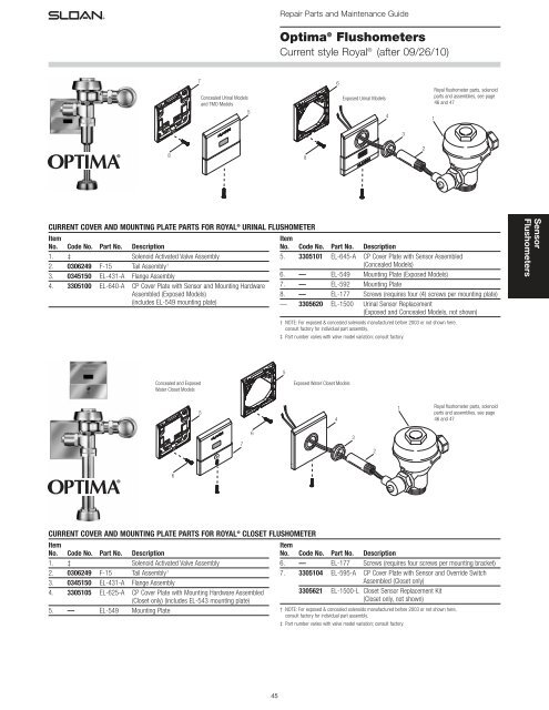
Repair Parts and <strong>Maintenance</strong> <strong>Guide</strong><br />
Optima ® <strong>Flushometers</strong><br />
Current style Royal ® (after 09/26/10)<br />
7<br />
Concealed Urinal Models<br />
and TMO Models<br />
5<br />
6<br />
Exposed Urinal Models<br />
4<br />
Royal flushometer parts, solenoid<br />
parts and assemblies, see page<br />
46 and 47<br />
1<br />
3<br />
2<br />
8 8<br />
CURRENT COVER AND MOUNTING PLATE PARTS FOR ROYAL ® URINAL FLUSHOMETER<br />
Item<br />
No. Code No. Part No. Description<br />
1. ‡ Solenoid Activated <strong>Valve</strong> Assembly<br />
2. 0306249 F-15 Tail Assembly †<br />
3. 0345150 EL-431-A Flange Assembly<br />
4. 3305100 EL-640-A CP Cover Plate with <strong>Sensor</strong> and Mounting Hardware<br />
Assembled (Exposed Models)<br />
(includes EL-549 mounting plate)<br />
Item<br />
No. Code No. Part No. Description<br />
5. 3305101 EL-645-A CP Cover Plate with <strong>Sensor</strong> Assembled<br />
(Concealed Models)<br />
6. — EL-549 Mounting Plate (Exposed Models)<br />
7. — EL-592 Mounting Plate<br />
8. — EL-177 Screws (requires four (4) screws per mounting plate)<br />
— 3305620 EL-1500 Urinal <strong>Sensor</strong> Replacement<br />
(Exposed and Concealed Models, not shown)<br />
† NOTE: For exposed & concealed solenoids manufactured before 2003 or not shown here,<br />
consult factory for individual part assembly.<br />
‡ Part number varies with valve model variation; consult factory.<br />
<strong>Sensor</strong><br />
<strong>Flushometers</strong><br />
5<br />
Concealed and Exposed<br />
Water Closet Models<br />
Exposed Water Closet Models<br />
5<br />
4<br />
1<br />
Royal flushometer parts, solenoid<br />
parts and assemblies, see page<br />
46 and 47<br />
7<br />
6<br />
3<br />
2<br />
6<br />
CURRENT COVER AND MOUNTING PLATE PARTS FOR ROYAL ® CLOSET FLUSHOMETER<br />
Item<br />
No. Code No. Part No. Description<br />
1. ‡ Solenoid Activated <strong>Valve</strong> Assembly<br />
2. 0306249 F-15 Tail Assembly †<br />
3. 0345150 EL-431-A Flange Assembly<br />
4. 3305105 EL-625-A CP Cover Plate with Mounting Hardware Assembled<br />
(Closet only) (includes EL-543 mounting plate)<br />
5. — EL-549 Mounting Plate<br />
Item<br />
No. Code No. Part No. Description<br />
6. — EL-177 Screws (requires four screws per mounting bracket)<br />
7. 3305104 EL-595-A CP Cover Plate with <strong>Sensor</strong> and Override Switch<br />
Assembled (Closet only)<br />
3305621 EL-1500-L Closet <strong>Sensor</strong> Replacement Kit<br />
(Closet only, not shown)<br />
† NOTE: For exposed & concealed solenoids manufactured before 2003 or not shown here,<br />
consult factory for individual part assembly.<br />
‡ Part number varies with valve model variation; consult factory.<br />
45
Repair Parts and <strong>Maintenance</strong> <strong>Guide</strong><br />
Optima ® <strong>Flushometers</strong><br />
Old Royal ® until 05/09, current <strong>Sloan</strong>/Regal ®<br />
<strong>Sensor</strong><br />
<strong>Flushometers</strong><br />
ABBREVIATIONS:<br />
CP - Chrome Plated<br />
RB - Rough Brass<br />
gpf - gallons per flush<br />
Lpf - Liters per flush<br />
NOTE: Gang box<br />
is not supplied.<br />
21<br />
20<br />
19<br />
Exposed<br />
or Concealed<br />
Water Closet<br />
18<br />
15<br />
16<br />
Concealed<br />
Urinal<br />
SOLENOID/SENSOR PARTS AND ASSEMBLIES LIST<br />
Item<br />
No. Code No. Part No. Description<br />
1A. 3305043 EL-128-A Actuator Cartridge Assembly Repair Kit Includes<br />
Spring, Plunger <strong>Guide</strong>, Solenoid <strong>Valve</strong> Seat, <strong>Valve</strong><br />
Piston Assembly, and O-Ring (also available for<br />
ES-SM flushometers)<br />
1B. 0305135 EL-110 O-Ring<br />
2A. 0305328 EL-124-1 120V only (no sensor)<br />
3305044 EL-1029-A CP Cartridge/Solenoid Kit EL-124-1 (120V) and<br />
EL128-A<br />
0305329 EL-124-2 24 VAC Solenoid Assembly (exposed installation)<br />
Includes Handle Coupling, 24 VAC Coil, Face Plate for<br />
24 VAC Solenoid, Solenoid Adapter, Solenoid Shaft<br />
Assembly, Nut for Solenoid, Solenoid Housing,<br />
Solenoid Flux Plate, and O-Ring<br />
3305045 EL-1028-A CP Cartridge/Solenoid Kit EL-124-2 (24V) and EL128-A<br />
2B. 0305330 EL-138-1 120V only (no sensor)<br />
0305331 EL-138-2 24 VAC Solenoid Assembly (concealed installation)<br />
Includes Handle Coupling, 24 VAC Coil, Face Plate for<br />
24 VAC Solenoid, Solenoid Adapter, Solenoid Shaft<br />
Assembly, Nut for Solenoid, Solenoid Base Plate and<br />
Solenoid Cover Assembly<br />
3A. 0337086 DO-22 O-Ring<br />
3B. 0305132 EL-104 RB Adapter for Solenoid<br />
3C. 0305165 EL-163-A Solenoid Shaft Assembly Includes Gasket, Plunger,<br />
Plunger Spring, and Solenoid Shaft<br />
4. 0301082 A-6 CP Handle Coupling (exposed installation)<br />
5A. 0305166 EL-164 Solenoid Flux Plate (exposed installation) fine thread<br />
5B. — EL-542 N/A Separately<br />
6. 0305119 EL-165-1 120 V Coil<br />
0305118 EL-165-2 24 VAC Coil<br />
7A. 0345120 EL-162-2 CP Solenoid Housing (exposed installation) fine thread<br />
0305164 EL-162-1 CP Solenoid Housing (120V) course thread also used<br />
on pre-2001 24 V<br />
7B. 0305336 EL-541-A Solenoid Cover Assembly (Includes Flux Plate)<br />
8. 0305127 EL-102-2 Face Plate for 24 VAC Solenoid (exposed installation)<br />
19<br />
17<br />
12<br />
12<br />
12<br />
Exposed<br />
Urinal<br />
14<br />
13<br />
19<br />
17<br />
Exposed or<br />
Concealed<br />
Water Closet<br />
11<br />
12<br />
26<br />
10†<br />
9A<br />
9B<br />
27<br />
8<br />
8<br />
12<br />
7B<br />
7A<br />
Exposed Urinal w/Overide<br />
3A<br />
6<br />
6<br />
1B<br />
5B<br />
5A<br />
Item<br />
No. Code No. Part No. Description<br />
9A. 0305125 EL-101 CP Nut for Solenoid (exposed installation)<br />
9B. 0305167 EL-166 Housing Nut for Solenoid (concealed installation)<br />
10. 0306249 F-15 Tail †<br />
0305145 EL-123-A Old Style ESS 24V course thread (120V also)<br />
0305337PK EL-226 1-1/4” Extension for EL-123-A course thread<br />
11. 0345150 EL-431-A CP Flange Assembly (exposed installation)<br />
0305139 EL-176-A Old Style ESS 24V course thread (120V also)<br />
12. 0305152 EL-152 CP Screws (requires four screws per cover plate)<br />
13. 0305151 EL-151 CP Cover Plate for <strong>Sensor</strong> and Solenoid Operator<br />
(Urinal only)<br />
14. 0305219 EL-201 CP Cover Plate for <strong>Sensor</strong> and Override Button<br />
(Closet only)<br />
15. 0318066 HY-66 CP Cover Plate for Solenoid Operator (Closet only)<br />
16. 0305161 EL-161 CP Cover Plate for <strong>Sensor</strong><br />
17. 0305323 EL-168-A Yoke Assembly (Urinal only)<br />
18. 0305324 EL-141-A Override Switch and Yoke Assembly (Closet only)<br />
19. 3305620 EL-1500 Urinal <strong>Sensor</strong> Replacement Kit (Urinal only)<br />
20. 3305621 EL-1500-L Closet <strong>Sensor</strong> Replacement Kit (Closet only)<br />
21. 0345154 EL-154 Transformer (120 VAC) (also available for ES-SM<br />
flushometers) 50 VA plate mount<br />
0345999 EL-342 Transformer (240 VAC) (also available for ES-SM<br />
flushometers) 50 VA plate mount<br />
22. 3345047 EL-461 Surface Mounted <strong>Sensor</strong> and Override Button<br />
Assembly (closet only)<br />
23. 3345048 EL-497 Surface Mounted <strong>Sensor</strong> Assembly (urinal only)<br />
24. 3345048 EL-297 Solenoid Assembly<br />
25. 3365003 ETF-492-A Control Module<br />
26. 0345266 EL-566-A Exposed Plate with Override Button (Urinal only)<br />
27. 0345267 EL-567-A Yoke Assembly for EL-566-A<br />
— 0305148 EL-227 Repair Tool Kit for EL-163-A Repair Kit<br />
— 0345016 EL-387-A Override Button Replacement for EL-566-A<br />
† NOTE: For exposed & concealed solenoids manufactured before 2001 or not shown here,<br />
consult factory for individual part assembly.<br />
4<br />
2A Exposed Solenoid<br />
4<br />
2B Concealed Solenoid<br />
3C<br />
3C<br />
3A<br />
3B<br />
3B<br />
1B<br />
3A<br />
3A<br />
To <strong>Valve</strong><br />
Royal ® ES-SM Surface Mounted <strong>Sensor</strong> Components<br />
Note: Royal ES-SM<br />
surface mounted<br />
components are<br />
not compatible with<br />
ES-S flushometer<br />
24<br />
components.<br />
22 23<br />
25<br />
Concealed Water Closet Concealed Urinal ES-SM Solenoid<br />
1A<br />
To<br />
<strong>Valve</strong><br />
1A<br />
46
Repair Parts and <strong>Maintenance</strong> <strong>Guide</strong><br />
Optima ® Royal ® <strong>Flushometers</strong><br />
1<br />
TO SOLENOID<br />
(SEE PAGE 46)<br />
6<br />
2<br />
3<br />
43<br />
4<br />
ABBREVIATIONS:<br />
CP Chrome Plated<br />
RB Rough Brass<br />
SD Screwdriver<br />
WH Wheel Handle<br />
gpf gallons per flush<br />
Lpf Liters per flush<br />
7<br />
5<br />
17<br />
11<br />
10<br />
8<br />
15<br />
18<br />
14<br />
13<br />
9<br />
CONCEALED WH<br />
21<br />
22<br />
19<br />
20<br />
12<br />
16<br />
OPTIMA ® ROYAL ® FLUSHOMETER PARTS LIST<br />
Item<br />
No. Code No. Part No. Description<br />
1. 0301172 A-72 CP Cover<br />
2. 0301168 A-71 Inside Cover<br />
3. SEE DIAPHRAGM ASSEMBLY CHART ON PAGE 42<br />
4. 3323182 V-651-A Vacuum Breaker Repair Kit<br />
5. 3393004 V-600-AA 3/4" (19 mm) x 9" (229 mm) CP Vacuum Breaker<br />
3393006 V-600-AA 1-1/4" (32 mm) x 9" (229 mm) CP Vacuum Breaker<br />
3393007 V-600-AA 1-1/2" (38 mm) x 9" (229 mm) CP Vacuum Breaker<br />
6. 0306125 F-5-AW 3/4" (19 mm) CP Spud Coupling Assembly<br />
0306140 F-5-AU 1-1/4" (32 mm) CP Spud Coupling Assembly<br />
0306146 F-5-AT 1-1/2" (38 mm) CP Spud Coupling Assembly<br />
7. SEE SLIP JOINT GASKETS AND RINGS TABLE ON ITEM 31A ON NEXT PAGE<br />
8. 0308676 H-550 CP Stop Coupling<br />
9. 0308801 H-551-A CP Adjustable Tail 2-1/16" (52 mm) long<br />
10. 5308696 H-553 O-Ring – 24 per package<br />
11. 5308381 H-552 Locking ring – 12 per package<br />
12. 3308386 H-700-A 1" (25 mm) Screwdriver Bak-Chek ® Angle Stop<br />
CP – complete<br />
3308384 H-700-A 3/4" (19 mm) Screwdriver Bak-Chek ® Angle Stop<br />
CP – complete<br />
13. 3308853 H-541-A-SD Control Stop Repair Kit for use with 1" (25 mm)<br />
H-700-A & 3/4" (19 mm) H-700-A, 1" (25 mm)<br />
H-600-A, 1" (25 mm) & 3/4" (19 mm) H-700-A<br />
and 1" (25 mm) H-540-A SD Stops<br />
3308856 H-543-A-SD Control Stop Repair Kit for use with 3/4" (19 mm)<br />
H-600-A and H-540-A SD Stops<br />
14. 0308612 H-622 CP Bonnet for use with 1" (25 mm) & 3/4" (19 mm)<br />
H-700-A and 1" (25 mm) H-600-A SD Stops<br />
0308843 H-577 CP Bonnet for use with 3/4" (19 mm) H-600-A<br />
SD Stops – OBSOLETE<br />
15. 3308772 H-1010-A 1" (25 mm) Vandal Resistant Control Stop Cap<br />
Assembly for use with 1" (25 mm) & 3/4"<br />
(19 mm) H-700-A and 1" (25 mm)<br />
H-600-A SD Stops<br />
3308790 H-1009-A 3/4" (19 mm) Vandal Resistant Control Stop Cap<br />
Assembly for use with 3/4" (19 mm)<br />
H-600-A SD Stops<br />
16. 0308840 H-573 1" (25 mm) Control Stop Cap CP for use with<br />
1" (25 mm) & 3/4" (19 mm) H-700-A and<br />
1" (25 mm) H-600-A SD Stops<br />
0308848 H-582 3/4" (19 mm) Control Stop Cap CP for use with<br />
3/4" (19 mm) H-600-A SD Stops<br />
17. 3308866 H-574 1" (25 mm) Control Stop Cap with Bumper for use<br />
with 1" (25 mm) & 3/4" (19 mm) H-700-A and<br />
1" (25 mm) H-600-A SD Stops<br />
18. 3308867 H-576 1" (25 mm) Control Stop Cap with Extended<br />
Bumper for use with 1" (25 mm) & 3/4" (19 mm)<br />
H-700-A and 1" (25 mm) H-600-A SD Stops<br />
19. 3308860 H-1006-A Repair Kit for 1" (25 mm) Stops with Concealed<br />
WH for use with 1" (25 mm) H-700-A, H-600-A,<br />
and H-543-AWH WH Series Stops<br />
3308859 H-1007-A Repair Kit 3/4" (19 mm) Stops with Concealed WH<br />
for use with 3/4" (19 mm) H-700-A WH<br />
Series Stops<br />
20. 0388010 H-730-A 1" (25 mm) Concealed WH Bak-Chek ®<br />
Angle Stop RB<br />
0388011 H-730-A 3/4" (19 mm) Concealed WH Bak-Chek ® Angle<br />
Stop RB<br />
21. 3308872 H-1011-A Repair Kit (for Concealed WH only; does not<br />
include bonnet)<br />
42. 0208083 H-623 Bonnet<br />
0308705 H-561 Bonnet – OBSOLETE<br />
43. 0301048 A-143-A CP <strong>Valve</strong> Body<br />
0301050 A-143-A RB <strong>Valve</strong> Body<br />
<strong>Sensor</strong><br />
<strong>Flushometers</strong><br />
47
Repair Parts and <strong>Maintenance</strong> <strong>Guide</strong><br />
Optima ® Regal ®<br />
<strong>Flushometers</strong><br />
NOTE: Also for use with Regal ® XL<br />
(Since mid-2010)<br />
OPTIMA ® REGAL ® FLUSHOMETER PARTS LIST<br />
<strong>Sensor</strong><br />
<strong>Flushometers</strong><br />
TO SOLENOID<br />
(SEE PAGE 46)<br />
7<br />
1<br />
8<br />
20<br />
9<br />
19<br />
16<br />
5<br />
2<br />
10<br />
17<br />
4<br />
18<br />
3<br />
14<br />
6<br />
15<br />
13<br />
Item<br />
No. Code No. Part No. Description<br />
1. 0301168 A-71 Inside Cover<br />
2. 0308676 H-550 CP Stop Coupling<br />
3. 0308801 H-551-A CP Adjustable Tail 2-1/16" (52 mm) long<br />
4. 5308696 H-553 O-Ring – 24 per package<br />
5. 5308381 H-552 Locking ring – 12 per package<br />
6. 3308853 H-541-A-SD Control Stop Repair Kit for use with 1" (25 mm)<br />
H-700-A & 3/4" (19 mm) H-700-A, 1" (25 mm)<br />
H-600-A, 1" (25 mm) & 3/4" (19 mm) H-700-A<br />
and 1" (25 mm) H-540-A SD Stops<br />
3308856 H-543-A-SD Control Stop Repair Kit for use with 3/4" (19 mm)<br />
H-600-A<br />
7. 0317004 R-10 CP Cover<br />
8. SEE INSIDE PARTS ASSEMBLY CHART ON PAGE 42<br />
9. 3323192 V-551-A Vacuum Breaker Repair Kit<br />
10. 5323005 V-500-AA 3/4" (19 mm) x 9" (229 mm) CP Vacuum Breaker<br />
5323006 V-500-AA 1-1/4" (32 mm) x 9" (229 mm) CP<br />
Vacuum Breaker<br />
5323007 V-500-AA 1-1/2" (38 mm) x 9" (229 mm) CP<br />
Vacuum Breaker<br />
11. 0306102 F-54-A 3/4" (19 mm) CP Spud Coupling Assembly<br />
0306142 F-55-A 1-1/4" (32 mm) CP Spud Coupling Assembly<br />
0306145 F-56-A 1-1/2" (38 mm) CP Spud Coupling Assembly<br />
12. SEE SLIP JOINT GASKETS AND RINGS TABLE BELOW<br />
13. 0388065 H-790-A 1" Screwdriver Stop Adjustable<br />
0388064 H-790-A 3/4" Screwdriver Stop Adjustable<br />
0388029 H-740-A 1" (25 mm) SD Bak-Chek ® Stop CP – complete<br />
OBSOLETE<br />
0388031 H-740-A 3/4" (19 mm) SD Bak-Chek ® Stop CP – complete<br />
OBSOLETE<br />
14. 0308612 H-622 CP Bonnet (Current Regal ® )<br />
0308991 H-639 CP Bonnet for use with 1" (25 mm) & 3/4"<br />
(19 mm) H-700-A and 1" (25 mm) H-540-A<br />
SD Stops – Pre 2010 Regal ® Stops<br />
0308601 H-538 CP Bonnet for use with H-700-A 3/4" (19 mm)<br />
SD Stop – OBSOLETE<br />
15. 5388001 H-1012-A CP Cap – 6 per package VP<br />
16. 5310034 J-2/J-7 Bumper Assembly – 6 per package – OBSOLETE<br />
17. 3308866 H-574 Stop Cap, chrome plated with Seat Bumper (-YO)<br />
18. 3308867 H-576 Stop Cap, chrome plated with Extended Seat<br />
Bumper (-YG)<br />
19. 5388002 H-528 Hole Plug<br />
20. 0301048 A-143-A CP <strong>Valve</strong> Body<br />
0301050 A-143-A RB <strong>Valve</strong> Body<br />
NOTE: Also refer to the Royal ® , Regal ® , control stop and flush connection sections.<br />
11<br />
12<br />
ITEM 31A. SLIP JOINT GASKETS AND RINGS<br />
Size Code No. Part No. Description<br />
1-1/2” 5306058 F-3 Red Friction Ring<br />
5322001 VBF-5 Black Slip Joint Gasket<br />
0319086/5319086 S-30 Flexible Seat<br />
0319079 S-21 Rigid Seat (rubber over brass)<br />
1-1/2” x 1-1/4” 0396062 F-105 Slip Joint Gasket – Rigid<br />
1-1/4” 5306057 F-3 Red Friction Ring<br />
5322176 VBF-5 Black Slip Joint Gasket<br />
0307052/5307052 G-21 Rigid Seat (rubber over brass)<br />
1” 5306056 F-3 Red Friction Ring<br />
5306115 F-5 Black Slip Joint Gasket<br />
3/4” 5306055 F-3 Red Friction Ring<br />
5306113 F-5 Black Slip Joint Gasket<br />
48
Repair Parts and <strong>Maintenance</strong> <strong>Guide</strong><br />
Optima ® <strong>Flushometers</strong><br />
ROYAL ® ESS (ITEM 24) REPAIR KIT<br />
Relief Refill Flow<br />
Code No. Part No. Description <strong>Valve</strong> Head* Ring<br />
3345013 EL-1101-A Low Consumption Water Closets-1.6 gpf (6.0 Lpf) Green Gray Smooth<br />
3345014 EL-1102-A Water Saver Water Closets-3.5 gpf (13.2 Lpf) White Gray Smooth<br />
3345015 EL-1103-A 9 Liter European Water Closets-2.4 gpf (9.0 Lpf) Blue Gray Smooth<br />
3345016 EL-1106-A Wash Down Urinals-0.5 gpf (1.9 Lpf) Green Black Smooth<br />
3345017 EL-1107-A Low Consumption Urinals-1.0 gpf (3.8 Lpf) Green Black Slotted<br />
3345018 EL-1108-A Water Saver Urinals-1.5 gpf (5.7 Lpf) Black Black Smooth<br />
To identify the Flush Volume of a<br />
DUAL FILTERED DIAPHRAGM<br />
ASSEMBLY, look at the color of the<br />
relief valve, the refill head and<br />
the shape of flow ring.<br />
DIAPHRAGM ONLY KIT<br />
Relief Refill Flow<br />
Code No. Part No. Description <strong>Valve</strong> Head* Ring<br />
3301502 A-1041-A Low Consumption Water Closets-1.6 gpf (6.0 Lpf) Green Gray Smooth<br />
3301501 A-1038-A Water Saver Water Closets-3.5 gpf (13.2 Lpf) White Gray Smooth<br />
3301506 A-1045-A High Efficiency Water Closets-1.28 gpf (4.8 Lpf) Blue Gray Smooth<br />
3301505 A-1044-A 9 Liter European Water Closets-2.4 gpf (9.0 Lpf) Blue Gray Smooth<br />
3301504 A-1043-A Wash Down Urinals-0.5 gpf (1.9 Lpf) Green Black Smooth<br />
3321503 A-1042-A Low Consumption Urinals-1.0 gpf (3.8 Lpf) Green Black Slotted<br />
3301500 A-1037-A Water Saver Urinals-1.5 gpf (5.7 Lpf) Black Black Smooth<br />
3301142 A-1047-A High Efficiency Urinals-0.25 gpf (1.0 Lpf) with White Inserts White HEU Black Smooth<br />
3301143 A-1050-A High Efficiency Urinals-0.125 gpf (0.5 Lpf) with Green Inserts White HEU Black Smooth<br />
*NOTE: Water closet refill heads (gray) have larger slots than urinal refill heads (black).<br />
*NOTE: Water closet refill<br />
heads (gray) have larger slots than<br />
urinal refill heads (black).<br />
<strong>Sensor</strong><br />
<strong>Flushometers</strong><br />
REGAL ® ESS (ITEM 28)<br />
INSIDE PARTS KITS ASSEMBLY<br />
4.5 gpf/<br />
17.0 Lpf<br />
1.5 gpf/<br />
5.7 Lpf<br />
3.5 gpf/<br />
13.2 Lpf<br />
1.6 gpf/<br />
6.0 Lpf<br />
1.0 gpf/<br />
3.8 Lpf<br />
0.5 gpf/<br />
1.9 Lpf<br />
2.4 gpf/<br />
9.0 Lpf<br />
NOTE: Also for use with Regal ® XL (Since mid-2010)<br />
Code No. Part No. Description<br />
3301036 A-36-A 4.5 gpf/17.0 Lpf-Closet<br />
3301037 A-37-A 1.5 gpf/5.7 Lpf-Urinal<br />
3301038 A-38-A 3.5 gpf/13.2 Lpf-Closet<br />
3301041 A-41-A 1.6 gpf/6.0 Lpf-Closet<br />
3301044 A-42-A 1.0 gpf/3.8 Lpf-Urinal<br />
3301081 A-43-A 0.5 gpf/1.9 Lpf-Urinal<br />
3301024 A-44-A 2.4 gpf/9.0 Lpf-Closet<br />
A-36-A<br />
Closet<br />
A-37-A<br />
Urinal<br />
A-38-A<br />
Closet<br />
A-41-A<br />
Closet<br />
A-42-A<br />
Urinal<br />
A-43-A<br />
Urinal<br />
A-44-A<br />
Closet<br />
REGAL ® INSIDE PARTS LIST** NOTE: Also for use with Regal ® XL (Since mid-2010)<br />
Item<br />
No. Code No. Part No. Description<br />
A. 5301058 A-19-AC Relief <strong>Valve</strong>, White (Closet)<br />
B. 5301059 A-19-AU Relief <strong>Valve</strong>, Black (Urinal)<br />
C. 5301211 A-19-ALC Relief <strong>Valve</strong>, Green (Closet/Urinal-Low Consumption)<br />
D. 0301143 A-19-AL Relief <strong>Valve</strong>, Blue (9 Liter Closet)<br />
E. 5301111 A-15-A Disc<br />
F. 5301188 A-156-A Diaphragm<br />
G. 5301236 A-163-A <strong>Guide</strong> Assembly 4.5 gpf/17.0 Lpf Closet and 1.5 gpf/5.7 Lpf Urinal<br />
H. 5301032 A-152-A <strong>Guide</strong> Assembly 3.5 gpf/13.2 Lpf Closet<br />
I. 5301031 A-151-A <strong>Guide</strong> Assembly 1.6 gpf/6.0 Lpf Closet<br />
J. 5301155 A-155-A <strong>Guide</strong> Assembly 1.0 gpf/3.8 Lpf Urinal<br />
K. 5301157 A-157-A <strong>Guide</strong> Assembly 0.5 gpf/1.9 Lpf Urinal<br />
**NOTE: All Regal ® inside part items are supplied in 12 per package.<br />
49
Repair Parts and <strong>Maintenance</strong> <strong>Guide</strong><br />
Optima ® <strong>Flushometers</strong><br />
<strong>Sensor</strong><br />
<strong>Flushometers</strong><br />
SOLENOID/SENSOR KITS LIST<br />
Code No. Part No. Description<br />
3305045 EL-124-2 CP 24 VAC Solenoid Assembly for exposed applications.<br />
Includes 24 VAC solenoid assembly and actuator cartridge<br />
assembly repair kit.<br />
3305154 EL-1001-A Closet flushometer Electronic Accessories Kit with Override.<br />
Includes screws, hex wrench, plate for 2-gang electrical box,<br />
mounting plate, override switch, yoke assembly, closet<br />
sensor replacement kit, an Optima ® sticker and sensor<br />
Installation Instructions.<br />
3305170 EL-1005-A Exposed Urinal flushometer Electronic Accessories Kit.<br />
Includes plate for 2-gang electrical box, four screws, yoke,<br />
hex wrench, washer, urinal sensor replacement kit, an<br />
Optima ® sticker and sensor Installation Instructions.<br />
3305172 EL-1007-A Concealed Urinal flushometer Accessories Kit. Includes<br />
screws, yoke, plate for 2-gang electrical box, hex wrench,<br />
washer, urinal sensor replacement kit, an Optima ® sticker<br />
and sensor Installation Instructions.<br />
EL-126<br />
EL-127<br />
EL-125<br />
EL-197<br />
EL-141-A<br />
(Water Closet only)<br />
EL-1500-L Closet<br />
EL-1500 Urinal<br />
WALL BOX KITS CLOSET MODELS<br />
Code No. Part No. Description<br />
3305180 EL-192-A Closet Wall Box Kit – Stainless Steel. Includes four Mounting<br />
Screws, four Hex Nuts, four Lock Washers, Mounting<br />
Bracket, Electrical Box, Electrical Box Cover, Override Switch<br />
Subassembly, Wall Box 13" x 17" (330 mm x 432 mm) with<br />
14.5” x 18.5” (368 mm x 470 mm) Stainless Steel Wall Box<br />
Cover with hole for override switch, Spanner Bit and Closet<br />
<strong>Sensor</strong> Replacement Kit.<br />
3305160 EL-192-ALS Same as EL-192-A. <strong>Sensor</strong> NOT included.<br />
WALL BOX KITS URINAL MODELS<br />
3305178 EL-191-A Urinal Wall Box Kit – Stainless Steel. Includes Mounting<br />
Screws, Hex Nuts, Lock Washers, Wall Box 13" x 17"<br />
(330 mm x 432 mm) with 14.5” x 18.5” (368 mm x 470 mm)<br />
Stainless Steel Wall Box Cover, Mounting Bracket, Electrical<br />
Box, Electrical Box Cover, Spanner Bit, Urinal <strong>Sensor</strong><br />
Replacement Kit.<br />
3305158 EL-191-ALS Same as EL-191-A. <strong>Sensor</strong> NOT included.<br />
WALL BOX PARTS<br />
0305845 EL-318 #8 Spanner Bit for WB-37 Spanner Screws (#8)<br />
0334021 WB-37 Spanner Head Screws for ESS WB<br />
5334000 WB-1000-A 6 Pack of WB-37 Screws<br />
— EL-216 Wall Box Frame and Stainless Steel Wall Box Cover for Water<br />
Closet. Mounting Hardware and <strong>Sensor</strong> NOT Included.<br />
— EL-193 Wall Box Frame and Stainless Steel Wall Box Cover for<br />
Urinal. Mounting Hardware and <strong>Sensor</strong> NOT Included.<br />
EL-195<br />
WB-6<br />
EL-196<br />
EL-125<br />
EL-216 Closet<br />
EL-193 Urinal<br />
Panel shown with<br />
hole for override<br />
switch (closet<br />
applications only)<br />
WB-37<br />
TYPICAL WIRING DIAGRAM FOR ONE FLUSH VALVE<br />
TYPICAL WIRING DIAGRAM FOR ONE OR MORE FLUSH VALVE(S)<br />
Override Button<br />
Override Button<br />
Override Button<br />
Override Button<br />
Transformer<br />
To <strong>Valve</strong><br />
24 VAC in<br />
To <strong>Valve</strong><br />
24 VAC in<br />
<strong>Sensor</strong><br />
<strong>Sensor</strong> <strong>Sensor</strong> <strong>Sensor</strong><br />
Transformer<br />
50
Repair Parts and <strong>Maintenance</strong> <strong>Guide</strong><br />
Optima ® <strong>Flushometers</strong><br />
51<br />
SENSOR REPLACEMENT<br />
NOTE: The EL-1500 series Optima sensor (a two-wire unit) replaces the<br />
older EL-150 series sensors (either three-wire or four-wire units). Refer to<br />
the wiring history shown below.<br />
IMPORTANT<br />
• Be certain to disconnect the 24 VAC power supply either at the<br />
transformer or the fuse box. Failure to disable the power supply can<br />
result in damage to the EL-1500 series sensor.<br />
• The solenoid activated must be removed from the valve on exposed urinal<br />
installations. Do not damage the O-ring seal on the operator assembly.<br />
1. Remove the cover plate (for wall box installation, remove cover panel) and<br />
old sensor from the wall installation. Use a 5/64" hex wrench to remove<br />
the cover plate screws (or #8 drilled spanner head screwdriver EL-318 to<br />
remove the vandal-resistant screws from the wall box cover panel.)<br />
FIGURE 1A<br />
ORIENTATION<br />
ARROW<br />
2. Connect one 24 VAC lead to the sensor terminal labeled “24 VAC IN”<br />
(see Figure 1B).<br />
• On an old three-wire series EL-150 sensor, this wire was connected<br />
to the BLACK sensor lead.<br />
• On an old four-wire series EL-150 sensor, this wire was connected to<br />
the BROWN sensor lead.<br />
3. Connect one solenoid lead to the sensor terminal labeled “TO VALVE”<br />
(see Figure 1B).<br />
• On an old three-wire or four-wire EL-150 series sensor, this wire was<br />
connected to the RED sensor lead.<br />
4. Connect the remaining 24 VAC lead to the remaining solenoid lead.<br />
• On an old three-wire series EL-150 sensor, these wires were<br />
connected to the WHITE sensor leads.<br />
• On an old four-wire EL-150 series sensor, these wires were connected<br />
to the YELLOW and BLUE (or in very early models, the inner BROWN)<br />
sensor leads.<br />
5. On Water Closet installations only, connect the override button (shown as<br />
the override switch in wiring diagram) parallel to the EL-1500-L sensor.<br />
6. Reinstall the sensor with the orientation arrow on the lens side of the<br />
sensor pointing UP (see Figure 1A). Replace the cover plate (or wall box<br />
panel) and tighten the cover plate (or wall box panel) screws.<br />
7. Reconnect the 24 VAC power supply at the transformer or the fuse box.<br />
WIRING DIAGRAM<br />
120 VAC<br />
FIGURE 2<br />
COMMON<br />
24 VAC<br />
EL-1500 SERIES SENSOR<br />
FIGURE 1B<br />
“24 VAC IN” CONNECTION<br />
GND<br />
“TO VALVE”<br />
CONNECTION<br />
START-UP MODE<br />
The self-adaptive sensor automatically adapts to the surrounding<br />
environment when 24 volt supply is activated. No manual adjustments are<br />
required. Start-up mode will take approximately one (1) minute to complete<br />
its cycle and is important that no non-permanent target is present at this<br />
time. A continuous red light visible in sensor window indicates sensor is in<br />
the start-up mode. If the red light is flashing, this indicates that the sensor is<br />
picking up a target. Unless this target is a permanent fixture in the sensor’s<br />
environment (i.e., wall or stall door), it must be removed from the view of the<br />
sensor. Then, either disconnect the 24 volt supply for twenty (20) seconds or<br />
more, or push the manual override button for more than twenty (20)<br />
seconds in closet set-up. Reconnect the 24 VAC power supply at the<br />
transformer or the fuse box. When the start-up cycle is complete, there will<br />
be no light visible in the sensor window.<br />
NOTE: If the 24 volt power supply is ever interrupted for longer than<br />
twenty (20) seconds, the start-up mode automatically begins when<br />
power is restored.<br />
Incorrect wiring or a short in the 24 volt power supply is indicated by a<br />
continuous warning signal seen in the senosr window. The visible red light<br />
flashes an “SOS” signal: three (3) slow, three (3) fast, three (3) slow flashes.<br />
EL-1500 SERIES<br />
SENSOR<br />
START-UP MODE (FOR PREVIOUS SENSOR)<br />
NOTE: It is important that only permanent targets are present at this time.<br />
The self-adaptive sensor automatically adjusts to the surrounding<br />
environment when the 24 volt supply is activated. No manual adjustment is<br />
required. The start-up cycle completes in approximately five (5) minutes. A<br />
continuous red light visible in the sensor window indicates the start-up<br />
mode. If the red light flashes, the sensor detects a target. Unless this target<br />
is a permanent fixture in the sensor’s environment (i.e., a wall or stall door),<br />
it must be removed from the view of the sensor. If a target is permanent, the<br />
sensor will adapt itself around this target. In this case, the start-up mode<br />
may take up to ten (10) minutes. When the start-up cycle is complete, the<br />
red light will no longer be visible in the sensor window.<br />
NOTE: If the 24 volt power supply is ever interrupted for longer than fifteen<br />
(15) seconds, the start-up mode begins automatically when power is<br />
restored.<br />
Incorrect wiring or a short in the 24 volt power supply will initiate a warning<br />
signal in the sensor window. The visible light flashes a continuous “S-O-S”<br />
signal: three (3) fast, three (3) slow, and three (3) fast flashes.<br />
EL-150 Wiring History for 4-wire and 3-wire sensors<br />
Release date 03/09/78<br />
brown red<br />
brown<br />
“24 VAC IN”<br />
red<br />
“TO VALVE”<br />
CONNECTION<br />
Release date 02/02/87<br />
blue red<br />
brown<br />
yellow<br />
<strong>Sensor</strong><br />
<strong>Flushometers</strong><br />
OVERRIDE<br />
SWITCH*<br />
24 VAC COIL<br />
COIL WIRE<br />
GROUND<br />
SCREW<br />
EL-1500 SERIES SENSOR<br />
IN SOLENOID<br />
HOUSING<br />
OVERRIDE<br />
SWITCH*<br />
24 VAC COIL<br />
COIL WIRE<br />
* OVERRIDE SWITCH USED WITH<br />
WATER CLOSETS ONLY<br />
GROUND SCREW<br />
IN SOLENOID<br />
HOUSING<br />
UNIT #1<br />
UNIT #2 THRU #10<br />
(IF USED)<br />
NOTE: A MAXIMUM OF TEN (10) SENSOR FLUSHOMETER UNITS CAN ACTIVATE FROM ONE (1) SLOAN<br />
EL-154 TRANSFORMER. CLASS 2 UL LISTED, 48 VA (MIN.) AT 24 VAC, PLATE MOUNTED.<br />
Release date 08/11/83<br />
brown red red<br />
brown<br />
with<br />
yellow or<br />
all yellow<br />
Release date 12/12/90<br />
red black white<br />
51
Repair Parts and <strong>Maintenance</strong> <strong>Guide</strong><br />
Optima ® <strong>Flushometers</strong><br />
<strong>Sensor</strong><br />
<strong>Flushometers</strong><br />
TROUBLESHOOTING GUIDE<br />
ATTENTION INSTALLERS: With the exception of the control stop inlet,<br />
DO NOT USE pipe sealant or plumbing grease on any valve component or<br />
coupling! To protect the chrome or special finish of <strong>Sloan</strong> flushometers,<br />
DO NOT USE toothed tools to install or service these valves. Use our A-50<br />
Super-Wrench or other smooth-jawed wrench to secure couplings.<br />
Regulations for low consumption fixtures (1.6 gpf/6.0 Lpf closets and<br />
1.0 gpf/3.8 Lpf urinals) prohibit use of higher flush volumes.<br />
Urinals (EL-1500 <strong>Sensor</strong>)<br />
When the sensor detects a user, a slow flashing red light appears in the<br />
sensor window. After eight (8) to ten (10) seconds, the light flashes rapidly<br />
to indicate that the sensor is armed. When the sensor no longer detects a<br />
user, the sensor immediately activates the solenoid valve after a 0.5 second<br />
delay.<br />
Water Closets (EL-1500-L <strong>Sensor</strong>)<br />
Detection and activation are the same as for the urinal EL-1500 sensor<br />
(ABOVE) except when the sensor no longer detects an user, the sensor<br />
activates the solenoid valve after a three (3) second delay.<br />
The EL-1500 urinal and EL-1500-L closet self-adaptive sensors are<br />
equipped with a “Sentinel Flush” feature. These units automatically activate<br />
the solenoid every twenty-four (24) hours after the last user.<br />
1. <strong>Valve</strong> does not function (red light does not flash when user<br />
steps in front of sensor).<br />
A. No power is being supplied to sensor. Ensure that the main power is<br />
turned “ON”. Check transformer, leads and connections. Repair or<br />
replace as necessary.<br />
B. EL-1500/EL-1500-L sensor is not operating. Replace sensor.<br />
2. <strong>Valve</strong> does not function (red light flashes when user steps in<br />
front of sensor).<br />
INDICATOR: The red light stops flashing when user steps away<br />
and the valve makes a “clicking” sound but does not flush.<br />
A. No water is being supplied to the valve. Make certain that water<br />
supply is turned “ON” and the control stop is open.<br />
B. EL-128-A cartridge is fouled or jammed. Turn electronic power to<br />
valve “OFF” (failure to do so could result in damage to the solenoid<br />
coil). Remove the solenoid operator from the valve and remove the<br />
EL-128-A cartridge. Clean and/or repair as necessary.<br />
INDICATOR: The red light stops flashing when user steps<br />
away but the valve does NOT make a “clicking” sound and<br />
does NOT flush.<br />
A. EL-163-A solenoid shaft assembly is fouled or jammed. Turn<br />
electronic power to valve “OFF” (failure to do so could result in<br />
damage to the solenoid coil). Remove EL-101 or EL-166 nut from the<br />
solenoid operator. Remove the coil from the solenoid operator. Use a<br />
spanner wrench or pliers to remove the EL-163-A solenoid shaft<br />
assembly from valve. Clean and/or replace as necessary. Be sure to<br />
replace plunger spring when reassembling solenoid shaft assembly.<br />
INDICATOR: The red light flashes three (3) fast flashes, three (3)<br />
slow flashes then three (3) fast flashes (“S-O-S”) and continues<br />
to repeat this cycle even when user steps out of the sensor’s<br />
detection range.<br />
A. EL-1500/EL-1500-L sensor wiring connections are incorrect. Rewire<br />
sensor to valve. One solenoid lead connects to the “TO VALVE”<br />
connection on sensor. One transformer lead connects to the “24 VAC<br />
IN” connection on sensor. Second solenoid lead and second<br />
transformer lead connect together.<br />
B. Wiring to sensor is ground shorted. Find short in wiring circuit and<br />
correct.<br />
C. EL-165-2 solenoid coil is burnt out or coil is not connected to<br />
solenoid plunger shaft. Reinstall or replace coil as necessary.<br />
3. Range too short.<br />
A. Power down unit for 30 seconds. Power up. Wait six minutes for<br />
calibration.<br />
B. If reset does not work, replace.<br />
4. Volume of water is insufficient to adequately siphon fixture.<br />
A. Control stop is not open wide enough. Adjust control stop for desired<br />
water delivery.<br />
B. Low consumption unit is installed on water saver or conventional<br />
fixture. Replace diaphragm component parts of valve with kit that<br />
corresponds to appropriate flush volume of fixture.<br />
C. Inadequate water volume or pressure available from supply. Increase<br />
pressure or supply (flow rate) to the valve. Consult factory for<br />
assistance.<br />
5. Length of flush is too long (long flushing) or valve fails<br />
to shut off.<br />
A. Water saver valve is installed on low consumption fixture. Replace<br />
diaphragm component parts of valve with kit that corresponds to<br />
appropriate flush volume of fixture.<br />
B. Relief valve in diaphragm is not seated properly or by-pass hole in<br />
diaphragm is clogged. Disassemble inside diaphragm component<br />
parts and wash parts thoroughly. Replace worn parts if necessary.<br />
6. Water splashes from fixture.<br />
A. Supply flow rate is more than necessary. Adjust control stop to meet<br />
flow rate required for proper cleansing of the fixture.<br />
B. Closet valve is installed on urinal fixture. Replace closet diaphragm<br />
component parts with proper urinal kit (inside diaphragm assembly or<br />
inside parts kit).<br />
CARE AND CLEANING INSTRUCTIONS<br />
DO NOT USE abrasive or chemical cleaners to clean flushometers or sensor<br />
that may dull the luster and attack the chrome or special decorative finishes.<br />
Use ONLY mild soap and water, then wipe dry with a clean towel or cloth.<br />
When cleaning the bathroom tile, protect the flushometer from any<br />
splattering of cleaner. Acids and cleaning fluids can discolor or remove<br />
chrome plating.<br />
When assistance is required, please contact<br />
<strong>Sloan</strong> Technical Support at: 1-888-SLOAN-14 (1-888-756-2614).<br />
52
Repair Parts and <strong>Maintenance</strong> <strong>Guide</strong><br />
Optima ® Royal ® ES-S TMO<br />
Exposed <strong>Flushometers</strong><br />
ROYAL ® OPTIMA ® ES-S TMO EXPOSED FLUSHOMETER PARTS LIST<br />
8<br />
7<br />
10<br />
4B<br />
12<br />
11<br />
1<br />
4A<br />
9A/9B<br />
2<br />
13<br />
3<br />
Item<br />
No. Code No. Part No. Description<br />
1. ‡ Solenoid Activated <strong>Valve</strong> Assembly<br />
2. ‡ H-700-A Bak-Chek ® Control Stop<br />
3. 3308772 H-1010-A Vandal Resistant Stop Cap<br />
4A. 3308782 H-633-AA 1" (25 mm) Sweat Solder Kit<br />
4B. 3308603 H-532 Adapter, 1" NPT to 1" Tube<br />
3308607 H-535. Adapter, 3/4" NPT to 3/4" Tube<br />
5A. — V-600-AA 1-1/2" (38 mm) Vacuum Breaker Assembly CP<br />
(Models 110/111, 115, and 116)<br />
5B. — V-600-AA 1-1/4" (32 mm) x 9" (229 mm) Vacuum Breaker<br />
Assembly CP (Model 180 ES-S)<br />
5C. — V-600-AA 3/4" (19 mm) x 9" (229 mm) Vacuum Breaker<br />
Assembly CP (Model 186 ES-S)<br />
6A. 0306146 F-5-AT 1-1/2" (38 mm) Spud Coupling Assembly CP<br />
(Models 110/111, 115, and 116)<br />
6B. 0306140 F-5-AU 1-1/4" (32 mm) Spud Coupling Assembly CP<br />
(Model 180)<br />
6C. 0306125 F-5-AW 3/4" (19 mm) Spud Coupling Assembly CP<br />
(Model 186)<br />
6D. SEE SLIP JOINT GASKETS AND RINGS ON TABLE BELOW<br />
7. ‡ F-15 Tail Assembly<br />
8. 0302323PK B-110-A Flange Assembly<br />
9A. 3305107 EL-635-A CP Cover Plate with <strong>Sensor</strong> (Mounting Plate and<br />
Screws included) (Models 110/111,<br />
115, and 116)<br />
9B. 3305101 EL-645-A CP Cover Plate with <strong>Sensor</strong> (Mounting Plate and<br />
Screws included) (Models 180 and 186)<br />
10. 0305329 EL-124-2 CP 24V Solenoid Assembly<br />
11. 0303009 C-2-A True Mechanical Override Button<br />
12. 3325814 EBV-1017-A CP <strong>Valve</strong> Handle Cap<br />
13. 0301082PK A-6 CP Nut<br />
14. 3345080 EL-1026-A ES-S to ES-S-TMO Conversion Kit Exposed<br />
includes Body/Tail assembly (no inside parts or<br />
covers) #11, #12, #13, DO-22 and EL-110 O rings<br />
<strong>Sensor</strong><br />
<strong>Flushometers</strong><br />
‡ Part number varies with valve model variation; consult factory.<br />
5A<br />
5B<br />
5C<br />
6A 6D 6B 6D 6C 6D<br />
ITEM 6D. SLIP JOINT GASKETS AND RINGS<br />
Size Code No. Part No. Description<br />
1-1/2” 5306058 F-3 Red Friction Ring<br />
5322001 VBF-5 Black Slip Joint Gasket<br />
0319086/5319086 S-30 Flexible Seat<br />
0319079 S-21 Rigid Seat (rubber over brass)<br />
1-1/2” x 1-1/4” 0396062 F-105 Slip Joint Gasket – Rigid<br />
1-1/4” 5306057 F-3 Red Friction Ring<br />
5322176 VBF-5 Black Slip Joint Gasket<br />
0307052/5307052 G-21 Rigid Seat (rubber over brass)<br />
1” 5306056 F-3 Red Friction Ring<br />
5306115 F-5 Black Slip Joint Gasket<br />
3/4” 5306055 F-3 Red Friction Ring<br />
5306113 F-5 Black Slip Joint Gasket<br />
53
Repair Parts and <strong>Maintenance</strong> <strong>Guide</strong><br />
Optima ® Royal ® ES-S TMO<br />
Concealed <strong>Flushometers</strong><br />
54<br />
ROYAL ® OPTIMA ® ES-S TMO CONCEALED FLUSHOMETER PARTS LIST<br />
<strong>Sensor</strong><br />
<strong>Flushometers</strong><br />
2<br />
Optima ES-S TMO<br />
Concealed Model 152<br />
9<br />
5<br />
Optima ES-S TMO<br />
Concealed Model 195<br />
1A/1B<br />
Item<br />
No. Code No. Part No. Description<br />
1A. 3305107 EL-635-A CP Cover Plate with <strong>Sensor</strong> (Mounting Screws<br />
included) (Model 152)<br />
1B. 3305101 EL-645-A CP Cover Plate with <strong>Sensor</strong> (Mounting Screws<br />
included) (Model 195)<br />
2. ‡ — <strong>Valve</strong> Assembly<br />
3. 3301093 A-1013-A Concealed <strong>Valve</strong> Handle Cap RB<br />
4. 0305331 EL-138-2 RB Concealed 24V Solenoid Assembly<br />
5. ‡ H-730-A RB Bak-Chek ® Control Stop<br />
6. 3318001 HY-83-A Actuator Cartridge<br />
7. 3318005 HY-109-A-1 <strong>Valve</strong> Actuator Assembly<br />
8. 0318093 HY-30 1/4" (6 mm) x 48” (1219 mm) Connecting Tubes<br />
9. 0318117 HY-100-A-1 Metal Push Button Assembly<br />
10. ‡ V-500-AA 1-1/2" (38 mm) Vacuum Breaker Assembly RB<br />
(Model 152)<br />
11. ‡ V-500-AA 3/4" (19 mm) Vacuum Breaker Assembly RB<br />
(Model 192)<br />
12A. 0306088 F-2-AT 1-1/2" (38 mm) Slip Joint Coupling Assembly RB<br />
(Model 152)<br />
12B. 0306054 F-2-AW 3/4" (19 mm) Slip Joint Coupling Assembly RB<br />
(Model 192)<br />
13A. ‡ F-110 1-1/4" (32 mm) Outlet Tube with Flange and<br />
Scoring (Model 152)<br />
13B. ‡ F-100 1-1/2" (38 mm) Outlet Tube with Flange and<br />
Scoring (Model 152)<br />
14A. 0306059 F-2-AU 1-1/4" (32 mm) Slip Joint Coupling Assembly RB<br />
(Model 152)<br />
14B. 0306088 F-2-AT 1-1/2" (38 mm) Slip Joint Coupling Assembly RB<br />
(Model 152)<br />
15. 0306091 F-2-A 1-1/2" (38 mm) Coupling with S-21 Gasket<br />
(Model 152)<br />
16. 0206146PK F-21 1-1/2" (38 mm) Double Male Slip Joint Elbow<br />
17. ‡ F-15-A ELL with 3/4" (19 mm) Tail<br />
18. 0306054 F-2-AW 3/4" (19 mm) Slip Joint Coupling<br />
18A. SEE SLIP JOINT GASKETS AND RINGS TABLE BELOW<br />
19. 0305190 EL-190-A Handle Adapter Assembly<br />
3<br />
19<br />
6<br />
‡ Part number varies with valve model variation; consult factory.<br />
4<br />
7<br />
8<br />
ITEM 18A. SLIP JOINT GASKETS AND RINGS<br />
18A<br />
13A/B<br />
10<br />
18A<br />
16<br />
12A<br />
12B<br />
17<br />
11<br />
18A<br />
18A<br />
Size Code No. Part No. Description<br />
1-1/2” 5306058 F-3 Red Friction Ring<br />
5322001 VBF-5 Black Slip Joint Gasket<br />
0319086/5319086 S-30 Flexible Seat<br />
0319079 S-21 Rigid Seat (rubber over brass)<br />
1-1/2” x 1-1/4” 0396062 F-105 Slip Joint Gasket – Rigid<br />
1-1/4” 5306057 F-3 Red Friction Ring<br />
5322176 VBF-5 Black Slip Joint Gasket<br />
0307052/5307052 G-21 Rigid Seat (rubber over brass)<br />
1” 5306056 F-3 Red Friction Ring<br />
5306115 F-5 Black Slip Joint Gasket<br />
3/4” 5306055 F-3 Red Friction Ring<br />
5306113 F-5 Black Slip Joint Gasket<br />
14A/B<br />
15<br />
18<br />
54
Repair Parts and <strong>Maintenance</strong> <strong>Guide</strong><br />
Optima ® Royal ® ES-S TMO with<br />
SWB Concealed <strong>Flushometers</strong><br />
22<br />
5<br />
2<br />
3<br />
23<br />
4<br />
7<br />
6<br />
10<br />
11<br />
12A<br />
12 12<br />
13A/B<br />
12B 12 12<br />
14A/B<br />
16 17<br />
15<br />
18<br />
9<br />
8<br />
19<br />
20<br />
21<br />
ROYAL ® OPTIMA ® ES-S TMO WITH SWB PARTS LIST<br />
Item<br />
No. Code No. Part No. Description<br />
1A. — WB-55-A Wall Box Cover Plate Assembly (Model 152)<br />
1B. — WB-60-A Wall Box Cover Plate Assembly (Model 195)<br />
2. ‡ — <strong>Valve</strong> Assembly<br />
3. 3301093 A-1013-A Concealed <strong>Valve</strong> Handle Cap RB<br />
4. 0305331 EL-138-2 RB Concealed 24V Solenoid Assembly<br />
5. ‡ H-730-A RB Bak-Chek ® Control Stop<br />
6. 3318001 HY-83-A Actuator Cartridge<br />
7. 3318005 HY-109-A-1 <strong>Valve</strong> Actuator Assembly<br />
8. 0318117 HY-30 1/4" (6 mm) x 48” (1219 mm) Connecting Tubes<br />
9. — — 12” x 12” x 4” Wall Box Assembly<br />
10. ‡ V-500-AA 1-1/2" (38 mm) Vacuum Breaker Assembly RB<br />
(Model 152)<br />
11. ‡ V-500-AA 3/4" (19 mm) Vacuum Breaker Assembly RB<br />
(Model 192)<br />
12. SEE SLIP JOINT GASKETS AND RINGS TABLE BELOW<br />
12A. 0306088 F-2-AT 1-1/2" (38 mm) Slip Joint Coupling Assembly RB<br />
(Model 152)<br />
12B. 0306054 F-2-AW 3/4" (19 mm) Slip Joint Coupling Assembly RB<br />
(Model 192)<br />
13A. ‡ F-110 1-1/4" (32 mm) Outlet Tube Flanged and Scored<br />
(Model 152)<br />
13B. ‡ F-100 1-1/2" (38 mm) Outlet Tube Flanged and Scored<br />
(Model 152)<br />
14A. 0306059 F-2-AU 1-1/4" (32 mm) Slip Joint Coupling Assembly RB<br />
(Model 152)<br />
14B. 0306088 F-2-AT 1-1/2" (38 mm) Slip Joint Coupling Assembly RB<br />
(Model 152)<br />
15. 0306091 F-2-A 1-1/2" (38 mm) Coupling with S-21 Gasket<br />
(Model 152) †<br />
16. 0206146PK F-21 1-1/2" (38 mm) Double Male Slip Joint Elbow<br />
17. 0306366 F-15-A ELL with 3/4" (19 mm) Tail (Model 195)†<br />
18. 0306054 F-2-AW 3/4" (19 mm) Slip Joint Coupling<br />
19. 0334017 WB-18 U-Type Nuts (4) 1/4-20<br />
20. — WB-49 Tamper Resistant Screws (4) 1/4-20 x 1-1/2<br />
21. — HY-126 Elbow Fitting (2)<br />
22. 0318078 HY-50-A Hydraulic Actuator Assembly<br />
23. 0305190 EL-190-A Handle Adapter Assembly<br />
† “L” Dimension available between the lengths of 2” and 10¾”<br />
‡ Part number varies with valve model variation; consult factory.<br />
<strong>Sensor</strong><br />
<strong>Flushometers</strong><br />
1A/1B<br />
ITEM 12. SLIP JOINT GASKETS AND RINGS<br />
Size Code No. Part No. Description<br />
1-1/2” 5306058 F-3 Red Friction Ring<br />
5322001 VBF-5 Black Slip Joint Gasket<br />
0319086/5319086 S-30 Flexible Seat<br />
0319079 S-21 Rigid Seat (rubber over brass)<br />
1-1/2” x 1-1/4” 0396062 F-105 Slip Joint Gasket – Rigid<br />
1-1/4” 5306057 F-3 Red Friction Ring<br />
5322176 VBF-5 Black Slip Joint Gasket<br />
0307052/5307052 G-21 Rigid Seat (rubber over brass)<br />
1” 5306056 F-3 Red Friction Ring<br />
5306115 F-5 Black Slip Joint Gasket<br />
3/4” 5306055 F-3 Red Friction Ring<br />
5306113 F-5 Black Slip Joint Gasket<br />
55
Repair Parts and <strong>Maintenance</strong> <strong>Guide</strong><br />
Optima ® Royal ® ES-S TMO (SWB)<br />
<strong>Flushometers</strong><br />
<strong>Sensor</strong><br />
<strong>Flushometers</strong><br />
TROUBLESHOOTING GUIDE<br />
Urinals (EL-1500 <strong>Sensor</strong>)<br />
When the sensor detects a user, a slow flashing red light appears in the<br />
sensor window. After eight (8) to ten (10) seconds, the light flashes rapidly to<br />
indicate that the sensor is armed. When the sensor no longer detects a user,<br />
the sensor immediately activates the solenoid valve after a 0.5 second delay.<br />
Water Closets (EL-1500-L <strong>Sensor</strong>)<br />
Detection and activation are the same as for the urinal EL-1500 sensor<br />
(ABOVE) except when the sensor no longer detects an user, the sensor<br />
activates the solenoid valve after a three (3) second delay.<br />
The EL-1500 urinal and EL-1500-L closet self-adaptive sensors are<br />
equipped with a “Sentinel Flush” feature. These units automatically activate<br />
the solenoid every twenty-four (24) hours after the last user.<br />
1. <strong>Valve</strong> does not function (red light does not flash<br />
when user steps in front of sensor).<br />
A. No power is being supplied to sensor. Ensure that the main power is<br />
turned “ON.” Check transformer, leads and connections. Repair or<br />
replace as necessary.<br />
B. EL-1500-L <strong>Sensor</strong> is not operating. Replace the EL-1500-L <strong>Sensor</strong>.<br />
2. <strong>Valve</strong> does not function (red light flashes when user steps in<br />
front of sensor).<br />
INDICATOR: Red light stops flashing when user steps away and<br />
valve makes a “clicking” sound but does not flush.<br />
A. No water is being supplied to the valve. Make certain that the water<br />
supply is turned “ON” and the Control Stop is open. No power is being<br />
supplied to sensor. Ensure that the main power is turned “ON.” Check<br />
transformer, leads and connections. Repair or replace as necessary.<br />
B. EL-128-A cartridge is fouled or jammed. Turn electronic power to<br />
valve “OFF” (failure to do so could result in damage to the solenoid<br />
coil. Remove the solenoid operator from the valve and remove the<br />
EL-128-A cartridge. Clean and/or repair as necessary.<br />
INDICATOR: The red light stops flashing when user steps<br />
away but the valve does NOT make a “clicking” sound and<br />
does NOT flush.<br />
A. EL-163-A solenoid shaft assembly is fouled or jammed.<br />
Turn electronic power to valve “OFF” (failure to do so could result in<br />
damage to the solenoid coil). Remove EL-101 or EL-166 nut from the<br />
solenoid operator. Remove the coil from the solenoid operator. Use a<br />
spanner wrench or pliers to remove the EL-163-A solenoid shaft<br />
assembly from valve. Clean and/or replace as necessary. Be sure to<br />
replace plunger spring when reassembling Solenoid Shaft Assembly.<br />
INDICATOR: The red light flashes three (3) short flashes,<br />
three (3) long flashes then three (3) short flashes (“S-O-S”) and<br />
continues to repeat this cycle even when user steps out of the<br />
sensor’s detection range.<br />
A. EL-1500-L <strong>Sensor</strong> wiring connections are incorrect. Rewire <strong>Sensor</strong> to<br />
valve. One solenoid lead connects to the “TO VALVE” connection on<br />
<strong>Sensor</strong>. One transformer lead connects to the “24 VAC IN” connection<br />
on <strong>Sensor</strong>. Second solenoid lead and second transformer lead connect<br />
together.<br />
B. Wiring to <strong>Sensor</strong> is ground shorted.<br />
Find short in wiring circuit and correct.<br />
C. EL-165-2 solenoid coil is burnt out or coil is not connected to solenoid<br />
plunger shaft. Reinstall or replace coil as necessary.<br />
3. Volume of water is insufficient to adequately siphon fixture.<br />
A. Control Stop is not open wide enough. Adjust control stop for desired<br />
water delivery.<br />
B. Low Consumption unit is installed on Water Saver or Conventional<br />
fixture. Replace Diaphragm component parts of valve with kit that<br />
corresponds to appropriate flush volume of fixture.<br />
C. Inadequate water volume or pressure available from supply.<br />
Increase pressure or supply (flow rate) to the valve. Consult factory<br />
for assistance.<br />
4. Length of flush is too long (long flushing) or valve fails<br />
to shut off.<br />
A. Water Saver valve is installed on Low Consumption fixture.<br />
Replace Diaphragm component parts of valve with kit that<br />
corresponds to appropriate flush volume of fixture.<br />
B. Relief valve in diaphragm is not seated properly or bypass hole in<br />
diaphragm is clogged. Disassemble inside Diaphragm component<br />
parts and wash parts thoroughly. Replace worn parts if necessary.<br />
5. Water splashes from fixture.<br />
A. Supply flow rate is more than necessary. Adjust Control Stop to meet<br />
flow rate required for proper cleansing of the fixture.<br />
6. Leakage occurring at the Push Button (Concealed models only).<br />
A. Damaged or worn seals or lime build up in the actuator cartridge.<br />
Replace with new HY-32-A cartridge.<br />
7. The flushometer does not flush or flushes only once and will not<br />
flush a second time when the button is pushed (Concealed<br />
models only).<br />
A. The plunger is lodged in the actuator cartridge or the plunger by-pass<br />
hole is clogged. Remove the actuator housing and cartridge from the<br />
flushometer. Clean under running water. If cartridge parts are worn,<br />
deteriorated or limed up and problem persists after cleaning, replace<br />
with new HY-83-A cartridge.<br />
1. Turn off water at the control stop.<br />
2. Unscrew the housing coupling nut from the flushometer.<br />
3. Remove the actuator housing from the flushometer. The tubing<br />
connections can be left intact.<br />
3. Remove the actuator cartridge from the flushometer body. Care<br />
should be taken so that upon removal the actuator does not<br />
abruptly separate due to spring compression within. If the actuator<br />
cartridge is lodged in the body cavity, grip the exposed portion<br />
gently with a pair of channel lock pliers and rotate back and forth to<br />
loosen the “O” ring seal.<br />
5. Separate the actuator housing to reveal the spring and plunger.<br />
B. Plastic Tubing Installed Incorrectly. Install Plastic Tubing Correctly.<br />
8. The flushometer does not flush and a small amount of leakage is<br />
visible below the valve (Concealed models only).<br />
A. Foreign material lodged in the cartridge. Remove the cartridge and<br />
inspect for foreign material. Clean under running water.<br />
B. Damaged or worn seals or lime build up in the actuator cartridge.<br />
Replace with new HY-32-A cartridge.<br />
1. Remove the button or actuator assembly from the wall or fixture.<br />
2. Disassemble the flange or button assembly from the actuator body.<br />
3. Unscrew the cartridge from the actuator body. Note: The metal push<br />
button was designed to be vandal-proof and thus requires removal<br />
from the wall for servicing.<br />
C. Plastic Tubing installed incorrectly. Install Plastic Tubing Correctly.<br />
CARE AND CLEANING INSTRUCTIONS<br />
DO NOT USE abrasive or chemical cleaners to clean flushometers or sensor<br />
that may dull the luster and attack the chrome or special decorative finishes.<br />
Use ONLY mild soap and water, then wipe dry with a clean towel or cloth.<br />
When cleaning the bathroom tile, protect the flushometer from any<br />
splattering of cleaner. Acids and cleaning fluids can discolor or remove<br />
chrome plating.<br />
When assistance is required, please contact<br />
<strong>Sloan</strong> Technical Support at: 1-888-SLOAN-14 (1-888-756-2614).<br />
56
Repair Parts and <strong>Maintenance</strong> <strong>Guide</strong><br />
SMOOTH ® Flushometer Hardwired<br />
Side-Mount-Operator-Over-The-Handle<br />
AC powered, sensor activated retrofit unit for<br />
exposed closet and urinal flushometers.<br />
PARTS LIST<br />
Item<br />
No. Code No. Part No. Description<br />
1. 3305201 EL-600-A Side Mount Operator for Water Closets (Toilets)<br />
and Urinals<br />
2. — EL-612-A Wall Flange Hardware Mounting Kit<br />
— — EL-601-A Replacement Power Adapter<br />
1<br />
2<br />
ACCESSORY TRANSFORMERS<br />
— 0345095 EL-386 120 VAC/6 VAC, 50/60 Hz (3 VA)<br />
Plug-in (will operate 1 unit)<br />
— 0345125 EL-451 120 VAC/6 VAC, 50/60 Hz (25 VA)<br />
Box Mount (will operate up to 8 units)<br />
<strong>Sensor</strong><br />
<strong>Flushometers</strong><br />
One EL-386 Transformer serves one (1)<br />
OPTIMA ® Closet/Urinal flushometer.<br />
One EL-451 Transformer serves up to eight (8)<br />
OPTIMA ® Closet/Urinal flushometers.<br />
57
Repair Parts and <strong>Maintenance</strong> <strong>Guide</strong><br />
SMOOTH ® Flushometer Hardwired<br />
Side-Mount-Operator-Over-The-Handle<br />
ADJUSTMENT PROCEDURES<br />
Mode A<br />
The SMOOTH unit may be reset to normal range by fully pressing and<br />
holding in the Override Handle until the Red LED light in the <strong>Sensor</strong> Window<br />
illuminates. Then immediately release the Override Handle.<br />
Mode B<br />
The SMOOTH unit may be set to reduced range for closet applications by<br />
pressing and holding in the Override Handle until the Red LED light in the<br />
<strong>Sensor</strong> Window flashes a slow long blinking light. Then immediately release<br />
the Override Handle.<br />
Mode C (Urinal Only)<br />
The SMOOTH unit may be set to reduced range by pressing and holding<br />
in the Override Handle until the Red LED light in the <strong>Sensor</strong> Window<br />
displays a rapid on and off blinking light. Then immediately release the<br />
Override Handle.<br />
CARE AND CLEANING OF CHROME AND SPECIAL FINISHES<br />
DO NOT use abrasive or chemical cleaners to clean flushometers as they<br />
may dull the luster and attack the chrome or special decorative finishes.<br />
Use ONLY mild soap and water, then wipe dry with clean cloth or towel.<br />
While cleaning the bathroom tile, the flushometer should be protected<br />
from any splattering of cleaner. Acids and cleaning fluids can discolor<br />
or remove chrome plating.<br />
When assistance is required, please contact<br />
<strong>Sloan</strong> Technical Support at: 1-888-SLOAN-14 (1-888-756-2614).<br />
<strong>Sensor</strong><br />
<strong>Flushometers</strong><br />
58
Repair Parts and <strong>Maintenance</strong> <strong>Guide</strong><br />
SLOAN ECOS ® Hardwired<br />
<strong>Flushometers</strong><br />
PARTS LIST<br />
1B<br />
1A<br />
2<br />
3<br />
5<br />
6<br />
7<br />
Item<br />
No. Code No. Part No. Description<br />
Items Included with the RESS Retrofit and Complete <strong>Sloan</strong> ECOS ®<br />
Electronic Hardwire <strong>Valve</strong>s Only<br />
1A. ‡ — <strong>Sloan</strong> ECOS ® Electronic Hardwire<br />
Dual Flush Assembly<br />
1B. ‡ — <strong>Sloan</strong> ECOS ® Electronic Single-Flush Assembly<br />
2. 3325001 EBV-1020-A 1.6 gpf/6.0 Lpf Closet Flex Tube Diaphragm Kit<br />
3. 5325122 EBV-95 Flush Volume Regulator (Green)<br />
4. — EL-612-A Solenoid Wall Flange<br />
5. 0325159 EBV-137 7/64" Hex Wrench<br />
6. 0305823 EBV-22 Strap Wrench<br />
7. 0325194 EBV-91 Range Adjustment Tool<br />
8. 0372031 WES-19 English Operation Instruction Plate<br />
— WES-22 Spanish Operation Instruction Plate<br />
9. 3325814 EBV-1017-A Handle Cap (RESS-C Retrofit Models only)<br />
Items Included with the Complete <strong>Sloan</strong> ECOS ®<br />
Electronic Hardwire <strong>Valve</strong>s Only<br />
10. 3308386 H-700-A 1" (25 mm) Bak-Chek ® Control Stop<br />
11. 3308797 H-1010-A Vandal Resistant Stop Cap<br />
12. 0305381PK EBV-36-A <strong>Valve</strong> Body<br />
13. — H-633-AA 1" (25 mm) Sweat Solder Kit<br />
14. — V-600-AA 1½" (38 mm) x 10" (254 mm) Vacuum Breaker<br />
(Model 110)<br />
— V-600-AA 1½" (38 mm) x 23" (584 mm) Vacuum Breaker<br />
(Model 115)<br />
0393049 V-600-AA 1½" (38 mm) x 26" (660 mm) Vacuum Breaker<br />
(Model 116)<br />
15. 0306146 F-5-AT 1½" Spud Coupling Assembly<br />
(Models 111, 115, and 116)<br />
15A. SEE SLIP JOINT GASKETS AND RINGS TABLE BELOW<br />
<strong>Sensor</strong><br />
<strong>Flushometers</strong><br />
‡ Part number varies with valve model variation; consult factory.<br />
The EBV-1020-A Kit is supplied with multiple Flush Volume Regulators. The installer must use the correct<br />
Regulator when installing the kit.<br />
9<br />
4<br />
12<br />
13<br />
8<br />
10<br />
11<br />
ITEM 15A. SLIP JOINT GASKETS AND RINGS<br />
Size Code No. Part No. Description<br />
1-1/2” 5306058 F-3 Red Friction Ring<br />
5322001 VBF-5 Black Slip Joint Gasket<br />
0319086/5319086 S-30 Flexible Seat<br />
0319079 S-21 Rigid Seat (rubber over brass)<br />
1-1/2” x 1-1/4” 0396062 F-105 Slip Joint Gasket – Rigid<br />
1-1/4” 5306057 F-3 Red Friction Ring<br />
5322176 VBF-5 Black Slip Joint Gasket<br />
0307052/5307052 G-21 Rigid Seat (rubber over brass)<br />
1” 5306056 F-3 Red Friction Ring<br />
5306115 F-5 Black Slip Joint Gasket<br />
3/4” 5306055 F-3 Red Friction Ring<br />
5306113 F-5 Black Slip Joint Gasket<br />
14<br />
FLEX TUBE DIAPHRAGM ASSEMBLY<br />
<strong>Sloan</strong> ECOS ® Electronic <strong>Valve</strong> Models Feature<br />
<strong>Sloan</strong>’s Exclusive Flex Tube Diaphragm for the<br />
ultimate in valve performance, reliability and<br />
chloramine resistance.<br />
15<br />
15A<br />
59
Repair Parts and <strong>Maintenance</strong> <strong>Guide</strong><br />
SLOAN ECOS ® Hardwired<br />
<strong>Flushometers</strong><br />
<strong>Sensor</strong><br />
<strong>Flushometers</strong><br />
RANGE ADJUSTMENT (ADJUST ONLY IF NECESSARY)<br />
The <strong>Sloan</strong> ECOS ® Electronic<br />
Hardwire flushometer has a<br />
factory set sensing range:<br />
Water Closet Models – 22”<br />
(559 mm) to 42” (1067 mm)<br />
Urinals 15” (381 mm) to 30”<br />
(762 mm)<br />
The Factory setting should<br />
be satisfactory for most<br />
installations.<br />
If the range is too short (i.e.,<br />
not picking up the user) or<br />
too long (i.e., picking up<br />
opposite wall or stall door)<br />
the range can be adjusted.<br />
COUNTER-<br />
CLOCKWISE<br />
Decreases<br />
the Range<br />
CLOCKWISE<br />
Increases<br />
the Range<br />
Note: Water does not<br />
have to be turned off to<br />
adjust range.<br />
Loosen the two screws on<br />
top of the unit. Remove the override button assembly. Remove the rubber<br />
plug from top of electronic sensor module to uncover the potentiometer.<br />
Range Adjustment Procedure<br />
For the first ten (10) minutes of operation, a visible light flashes in the<br />
sensing window of the <strong>Sloan</strong> ECOS ® Electronic Hardwire flushometer when a<br />
user is detected. The visible light feature can be reactivated after ten (10)<br />
minutes by turning the power off and on. Check the range by stepping<br />
toward the unit until the light flashes, indicating the sensor’s maximum<br />
detection limit. Adjust the range potentiometer screw located on top of the<br />
sensor module a few degrees CLOCKWISE to increase the range or a few<br />
degrees COUNTER-CLOCKWISE to decrease the range. Repeat this<br />
adjustment until the desired range is achieved.<br />
Always determine the sensing range with metal cover and lens<br />
window installed on top of the unit.<br />
Important: Adjust in small increments only! Range potentiometer<br />
adjustment screw rotates only ¾ of a turn; DO NOT over-rotate.<br />
When range adjustment is satisfactory, replace the rubber plug. Reinstall<br />
override button and tighten the two screws on top of the unit.<br />
TROUBLESHOOTING GUIDE<br />
1. <strong>Sensor</strong> flashes continuously only when user steps within range.<br />
A. Unit in Start-Up mode; no problem. This feature is active for the first<br />
ten (10) minutes of operation.<br />
2. <strong>Valve</strong> does not flush; sensor does not picking up the user.<br />
A. Range too short; increase the range.<br />
3. <strong>Valve</strong> does not flush; sensor picking up opposite wall or surface,<br />
or only flushes when someone walks by. light flashes<br />
continuously for first 10 minutes even with no one in front of<br />
the sensor.<br />
A. Range too long; shorten the range.<br />
4. <strong>Valve</strong> does not flush even after adjustment.<br />
A. Range Adjustment Potentiometer set at full "max" or full "min"<br />
setting. Readjust Potentiometer away from full "max" or "min" setting.<br />
B. Problem with the Electronic <strong>Sensor</strong> Module; replace the Electronic<br />
<strong>Sensor</strong> Module.<br />
TROUBLESHOOTING GUIDE (CONTINUED)<br />
5. <strong>Valve</strong> Does Not Shut Off.<br />
A. Bypass Orifice in Diaphragm is clogged with dirt or debris, or Bypass<br />
is clogged by an invisible gelatinous film due to "over-treated" water.<br />
Remove Flex Tube Diaphragm and wash under running water. Note:<br />
Size of Orifice in the Bypass is of utmost importance for the proper<br />
metering of water by the valve. DO NOT ENLARGE OR DAMAGE THIS<br />
ORIFICE. Replace Flex Tube Diaphragm if cleaning does not correct<br />
the problem.<br />
B. Dirt or debris fouling Stem or Flex Tube Diaphragm. Remove Flex Tube<br />
Diaphragm and wash under running water.<br />
C. O-ring on Stem of Flex Tube Diaphragm is damaged or worn. Replace<br />
O-ring if necessary.<br />
D. Problem with Electronic <strong>Sensor</strong> Module; replace <strong>Sensor</strong> Module.<br />
6. Not enough water to the fixture to flush properly.<br />
A. The wrong Flush Volume Regulator was installed in Flex Tube<br />
Diaphragm Kit. Install the correct Regulator (see Step 7 of these<br />
instructions).<br />
B. Wrong <strong>Sloan</strong> ECOS ® Electronic Hardwire model installed; i.e., 1.6 gpf<br />
model installed on 3.5 gallon closet fixture.<br />
C. Enlarged Bypass in Diaphragm. Replace the Flex Tube Diaphragm.<br />
D. Control Stop not adjusted properly. Readjust Control Stop.<br />
E. Inadequate volume or pressure at supply. Increase water pressure or<br />
supply (flow) to valve. Consult factory for assistance.<br />
7. Too much water to fixture.<br />
A. The wrong Flush Volume Regulator was installed in Flex Tube<br />
Diaphragm Kit. Install the correct Regulator (see Step 7 of these<br />
instructions).<br />
B. Control Stop not adjusted properly. Readjust the Control Stop.<br />
C. Wrong <strong>Sloan</strong> ECOS ® Electronic Hardwire model installed; i.e., 3.5 gpf.<br />
model installed on 1.6 gallon fixture. Replace with proper <strong>Sloan</strong><br />
ECOS ® Electronic Hardwire model.<br />
D. Dirt in Diaphragm Bypass. Clean under running water or replace Flex<br />
Tube Diaphragm. Note: The EBV-46-A Beam Deflector is no longer<br />
required or available for the <strong>Sloan</strong> ECOS ® Electronic Hardwire Dual<br />
Flush sensor.<br />
CARE AND CLEANING INSTRUCTIONS<br />
DO NOT USE abrasive or chemical cleaners to clean flushometers that may<br />
dull the luster and attack the chrome or special decorative finishes. Use<br />
ONLY mild soap and water, then wipe dry with a clean towel or cloth.<br />
When cleaning the bathroom tile, protect the flushometer from any<br />
splattering of cleaner. Acids and cleaning fluids can discolor or remove<br />
chrome plating.<br />
When assistance is required, please contact<br />
<strong>Sloan</strong> Technical Support at: 1-888-SLOAN-14 (1-888-756-2614).<br />
60
Repair Parts and <strong>Maintenance</strong> <strong>Guide</strong><br />
G2 Optima Plus ® Flushometer<br />
For use with <strong>Sloan</strong>’s G2 Optima Plus ® flushometer introduced May, 2003.<br />
For older Optima Plus ® flushometers (produced from 1992 – 2003) and<br />
Regal Pro ® Optima Plus ® flushometers see pages 66 thru 71.<br />
SENSOR MODULE COMPONENT PARTS<br />
1<br />
8<br />
3<br />
4<br />
5<br />
6<br />
7<br />
9<br />
24<br />
2<br />
23<br />
13<br />
12<br />
11<br />
Item<br />
No. Code No. Part No. Description<br />
1. 0325160 EBV-138-A G2 Cover/Ring/<strong>Sensor</strong> Assembly – Water Closet<br />
0325161 EBV-139-A G2 Cover/Ring/<strong>Sensor</strong> Assembly – Urinal<br />
0325166 EBV-149-A G2 Cover/Ring/<strong>Sensor</strong> Assembly – Water Closet<br />
w/Zurn Ring<br />
0325167 EBV-150-A G2 Cover/Ring/<strong>Sensor</strong> Assembly –<br />
Urinal w/Zurn Ring<br />
2. 0325168 EBV-142-A Cover Assembly<br />
3. 0325172 EBV-130-A Override Button Assembly includes screws & hex<br />
wrench<br />
0325170 EBV-132-A Screws (2) and Allen Wrench Only<br />
4. 0325169 EBV-131 Lens Window Cover<br />
5. 0325804 EBV-14 Locking Ring CP<br />
0325210 EBV-168 Locking Ring CP<br />
3325524 EBV-31-A Locking Ring – for Zurn <strong>Valve</strong>s<br />
6. 3325450 EBV-129-A-C G2 Electronic Module – Water Closet<br />
3325451 EBV-129-A-U G2 Electronic Module – Urinal<br />
7. 0325171 EBV-134 Cover Rest Plate<br />
8. 3325456 EBV-145-A Inside Cover Assembly (includes solenoid<br />
EBV-136-A)<br />
3325089 EBV-1010-A Inside Cover Assembly (excludes solenoid)<br />
9. 3325453 EBV-136-A Solenoid (For G2 Modules only)*<br />
10. SEE CHART NEXT PAGE Flex Tube Diaphragm Kit<br />
<strong>Sensor</strong><br />
<strong>Flushometers</strong><br />
22<br />
* Refer to Page 58 for instructions regarding solenoid replacement.<br />
ACCESSORIES<br />
10<br />
19A<br />
19B<br />
21<br />
20<br />
11. 0325107 EBV-91 Trimpot Adjustment Screwdriver<br />
12. 0305823 EBV-22 Strap Wrench<br />
13. 0325170 EBV-132-A Allen Wrench<br />
VALVE COMPONENT PARTS<br />
A-3 Body<br />
25<br />
26<br />
Earlier model with<br />
EBV-36-A body<br />
16A<br />
17<br />
14<br />
15<br />
16<br />
18<br />
14. 3323182 V-651-A Vacuum Breaker Repair Kit<br />
15. 0393004 V-600-AA 3/4’’ x 9’’ CP Vacuum Breaker<br />
0393006 V-600-AA 1-1/4’’ x 9’’ CP Vacuum Breaker<br />
3393007 V-600-AA 1-1/2’’ x 9’’ CP Vacuum Breaker<br />
16. 0306125 F-5-AW 3/4’’ CP Spud Coupling<br />
0306140 F-5-AU 1-1/4’’ CP Spud Coupling<br />
0306146 F-5-AT 1-1/2’’ CP Spud Coupling<br />
16A. SEE SLIP JOINT GASKETS AND RINGS TABLE ON NEXT PAGE<br />
17. 0308676 H-550 CP Stop Coupling<br />
18. 0308801 H-551-A CP Adjustable Tailpiece 2-1/16’’ long<br />
19A. 5308696 H-553 O-ring – 24 per package<br />
19B. 5308381 H-552 Locking ring – 12 per package<br />
20. 3308386 H-700-A 1’’ Screwdriver Bak-Chek ® Stop CP – complete<br />
3308384 H-700-A 3/4’’ Screwdriver Bak-Chek ® Stop CP – complete<br />
21. 3308853 H-541-A Control Stop Repair Kit †<br />
3308856 H-543-A Control Stop Repair Kit ‡ 3/4” H-540/H-600 only<br />
22. 0308612 H-622 CP Bonnet †<br />
0308843 H-577 CP Bonnet ‡ – OBSOLETE<br />
23. 3308772 H-1010-A Vandal Resistant Control Stop Cap Assembly †<br />
3308790 H-1009-A Vandal Resistant Control Stop Cap Assembly ‡<br />
24. 3325816 EBV-1019-A 3/4’’ Decorative Stop Cap<br />
3308866 H-574 1’’ Decorative Stop Cap<br />
25. 3325814 EBV-1017-A Handle Cap — Metal<br />
26. 0311042 K-46 Blind Nut Gasket<br />
† For use with 1” and 3/4” H-700-A and 1” H-600-A Bak-Chek ® screwdriver control stop<br />
‡ For use with H-600-A 3/4’’ screwdriver Bak-Chek ® control stops<br />
61
Repair Parts and <strong>Maintenance</strong> <strong>Guide</strong><br />
G2 Optima Plus ® Flushometer<br />
<strong>Sensor</strong><br />
<strong>Flushometers</strong><br />
<strong>Sloan</strong> introduced its Optima Plus ® battery powered sensor flushometer in<br />
1992, revolutionizing the flushing of water closets and urinals. In both new<br />
construction and retrofit applications, the use of the Optima Plus has<br />
become the standard method for many facilities to improve restroom<br />
hygiene and ensure handicap accessibility compliance.<br />
In May, 2003 <strong>Sloan</strong> introduced the G2 Optima Plus.<br />
The G2 Optima Plus builds on the success of the original product and offers<br />
many technological advancements to further improve on performance and<br />
reliability expected of sensor activated plumbing. In addition to a new<br />
aesthetic design, the G2 Optima Plus features a new state-of-the-art<br />
electronic and optical package and a unique solenoid operator that keeps the<br />
moving components of the solenoid completely isolated from the water<br />
supply. This ensures long life and low maintenance regardless of local<br />
water condition.<br />
The G2 Optima Plus replaces the original Optima Plus product, which was<br />
phased out of production in mid-2003.<br />
The <strong>Sloan</strong> G2 Optima Plus automatic battery powered flushometer relies on<br />
an infrared sensor to detect a user and activate a flushing cycle. No physical<br />
contact with the flushometer surface is necessary, assuring sanitary<br />
protection. G2 Optima Plus flushometers are ADA compliant devices.<br />
The flushometer is triggered by means of an active infrared sensor. The<br />
Optima Plus sensor emits a continuous invisible light beam. When a user<br />
enters the beam’s effective range, the beam is reflected into the Optima<br />
Plus scanner window. The user is now detected. After the user moves out of<br />
the effective range of the sensor, a signal is sent to the flushometer solenoid<br />
and, after appropriate arming and/or flush delays, the flush cycle is initiated.<br />
ITEM 10. FLEX TUBE DIAPHRAGM KIT<br />
Regulator<br />
Code No. Part No. Description Color *<br />
3325090 EBV-1025-A Urinal-0.25 gpf/1.0 Lpf GREEN<br />
3325003 EBV-1023-A Urinal-0.5 gpf/1.9 Lpf †‡ GREEN<br />
3325000 EBV-1022-A Urinal-1.0 gpf/3.8 Lpf GREEN<br />
3325000 EBV-1022-A Urinal-1.5 gpf/5.7 Lpf † BLACK<br />
3325001 EBV-1020-A Urinal-3.5 gpf/13.2 Lpf † WHITE<br />
3325031 EBV-1024-A Closet-1.28 gpf/4.8 Lpf GREEN<br />
3325001 EBV-1020-A Closet-1.6 gpf/6.0 Lpf † GREEN<br />
3325014 EBV-1021-A Closet-2.4 gpf/9.0 Lpf BLUE<br />
3325001 EBV-1020-A Closet-3.5 gpf/13.2 Lpf WHITE<br />
3325001 EBV-1020-A Closet-4.5 gpf/17.0 Lpf § WHITE<br />
† EBV-1020-A and EBV-1022-A are supplied with multiple regulators.<br />
‡ A 0.5 gpf (1.9 Lpf) urinal kit can be converted to a 1.0 gpf (3.8 Lpf) by cutting and removing the<br />
smooth A-164 flow ring from the guide.<br />
§ For a 4.5 gpf (17 Lpf) water closet flush use EBV-1020-A with the white regulator, and cut and remove the<br />
A-164 flow ring from the guide.<br />
* Color of regulator to be used with flex tube diaphragm to obtain the listed flush volume.<br />
O-RING<br />
Code No. Part No. Description<br />
5325056 EBV-83 O-ring – 6 per package<br />
REGULATOR<br />
O-RING<br />
(Code No.<br />
5325056)<br />
REGULATOR<br />
(MUST BE<br />
INSTALLED<br />
PAST 0-RING)<br />
COVER<br />
LOCKING RING<br />
BODY<br />
FLUSH CONNECTION<br />
(VACUUM BREAKER)<br />
SPUD COUPLING<br />
TAILPIECE<br />
OVERRIDE BUTTON<br />
STOP COUPLING<br />
OUTLET COUPLING<br />
SPUD FLANGE<br />
CONTROL<br />
STOP<br />
SUPPLY FLANGE<br />
REGULATORS<br />
The flush volume of the flex tube diaphragm kit is controlled by the<br />
regulator. Regulators are identified by color. Some flex tube diaphragm kits<br />
are supplied with multiple regulators. The installer must make sure the<br />
proper regulator is used when installing the flex tube diaphragm kit.<br />
REGULATOR (SOLD 6 PER PACKAGE)<br />
Regulator<br />
Code No. Part No. Description Color<br />
5325122 EBV-95 Urinal-0.25 gpf/1.0 Lpf GREEN<br />
5325122 EBV-95 Urinal-0.5 gpf/1.9 Lpf GREEN<br />
5325122 EBV-95 Urinal-1.0 gpf/3.8 Lpf GREEN<br />
5325129 EBV-102-2 Urinal-1.5 gpf/5.7 Lpf BLACK<br />
5325130 EBV-102-1 Urinal-3.5 gpf/13.2 Lpf WHITE<br />
5325122 EBV-95 Closet-1.28 gpf/4.8 Lpf GREEN<br />
5325122 EBV-95 Closet-1.6 gpf/6.0 Lpf GREEN<br />
5325130 EBV-102-1 Closet-3.5 gpf/13.2 Lpf WHITE<br />
5325128 EBV-101 Closet-2.4 gpf/9.0 Lpf BLUE<br />
EBV-1020-A and EBV-1022-A are supplied with multiple flush volume regulators.<br />
The installer must use the correct regulator when installing the kit.<br />
ITEM 16A. SLIP JOINT GASKETS AND RINGS<br />
Size Code No. Part No. Description<br />
1-1/2” 5306058 F-3 Red Friction Ring<br />
5322001 VBF-5 Black Slip Joint Gasket<br />
0319086/5319086 S-30 Flexible Seat<br />
0319079 S-21 Rigid Seat (rubber over brass)<br />
1-1/2” x 1-1/4” 0396062 F-105 Slip Joint Gasket – Rigid<br />
1-1/4” 5306057 F-3 Red Friction Ring<br />
5322176 VBF-5 Black Slip Joint Gasket<br />
0307052/5307052 G-21 Rigid Seat (rubber over brass)<br />
1” 5306056 F-3 Red Friction Ring<br />
5306115 F-5 Black Slip Joint Gasket<br />
3/4” 5306055 F-3 Red Friction Ring<br />
5306113 F-5 Black Slip Joint Gasket<br />
FLEX TUBE<br />
DIAPHRAGM<br />
62
Repair Parts and <strong>Maintenance</strong> <strong>Guide</strong><br />
G2 Optima Plus ® Flushometer<br />
SOLENOID REPLACEMENT<br />
Code No. Part No. Description<br />
3325453 EBV-136-A Solenoid operator<br />
For G2 Optima Plus ® modules (identified by a<br />
blue module).<br />
1. Turn off water and relieve pressure by loosening Tailpiece<br />
coupling and re-tighten. Loosen and remove top screws along<br />
with the outer cover assembly.<br />
5. Make sure all O-rings (2) are installed on the grey End cap<br />
of the new Isolated Operator. Install Isolated Operator by<br />
threading it (clockwise) into the Housing. Tighten with fingers<br />
beyond just snug.<br />
<strong>Sensor</strong><br />
<strong>Flushometers</strong><br />
6. Mount module on inner cover assembly. Reconnect the plastic<br />
clip on the battery door.<br />
2. Disconnect wire clip from battery door and remove module from<br />
inner metal cover assembly.<br />
7. Assemble outer cover assembly.<br />
3. Remove Solenoid by turning counter clockwise. Remove any<br />
remaining O-rings or parts in orifice.<br />
Back View<br />
Close up<br />
4. Remove black plastic Housing from the threaded end of new<br />
Isolated Operator by unscrewing (counterclockwise). It is normal<br />
to find fluid inside this housing.<br />
Note. Verify that rubber insert is installed<br />
8. Turn on water at control stop. Installation complete.<br />
Front View<br />
63
Repair Parts and <strong>Maintenance</strong> <strong>Guide</strong><br />
G2 Optima Plus ® Flushometer<br />
<strong>Sensor</strong><br />
<strong>Flushometers</strong><br />
BATTERY REPLACEMENT<br />
When G2 Optima Plus ® has approximately 4,000 flushes left, the same red<br />
light that appears at start-up will flash four (4) times quickly whenever an<br />
object is detected. When this occurs, we recommend changing the batteries<br />
as follows:<br />
When required, replace batteries with four (4) alkaline type AA batteries.<br />
Note: Water does not have to be turned off to replace batteries.<br />
Loosen the two (2) screws on top of unit. Remove the complete cover<br />
assembly. Lift the sensor module from its plate. Unplug the electrical<br />
connector from battery compartment cover. Loosen the retaining screw on<br />
battery compartment cover and remove battery compartment cover. Install<br />
four (4) alkaline type AA batteries exactly as illustrated at right.<br />
Install battery compartment cover and secure with retaining screw. Make<br />
certain that battery compartment cover is fully compressed against gasket<br />
to provide a seal; Do not overtighten. Plug the electrical connector into the<br />
battery compartment cover. Reinstall the sensor module onto the plate.<br />
Reinstall the complete cover assembly onto the plate. Tighten the two<br />
(2) screws on top of the unit.<br />
7/64” ALLEN WRENCH<br />
COVER ASSEMBLY<br />
SENSOR MODULE<br />
PLATE<br />
SENSOR MODULE (BACKSIDE SHOWN)<br />
RETAINING SCREW<br />
ELECTRICAL CONNECTOR<br />
RECEPTACLE<br />
BATTERY COMPARTMENT COVER<br />
RANGE ADJUSTMENT (ADJUST ONLY IF NECESSARY)<br />
The G2 Optima Plus has a factory set sensing range:<br />
Water closet models – 22" to 42" (559 mm to 1067 mm)<br />
Urinal models – 15" to 30" (381 mm to 762 mm)<br />
The Factory setting should be satisfactory for most installations.<br />
If the range is too short (i.e., not picking up users) or too long (i.e., picking<br />
up opposite wall or stall door) the range can be adjusted.<br />
Note: Water does not have to be turned off to adjust range.<br />
Loosen the two screws on top of the unit. Remove the override button.<br />
Remove the rubber plug from top of electronic sensor module to uncover<br />
the potentiometer.<br />
COUNTERCLOCKWISE<br />
Decreases<br />
Range<br />
CLOCKWISE<br />
Increases<br />
Range<br />
RANGE ADJUSTMENT PROCEDURE<br />
For the first ten (10) minutes of operation, a visible red light flashes in the<br />
sensing window of the G2 Optima Plus flushometer when a user is detected.<br />
This visible red light feature can be reactivated after ten (10) minutes by<br />
opening and closing the battery compartment door or holding the override<br />
button for (1) minute.<br />
Check the range by stepping toward the unit until the red light flashes,<br />
indicating the sensor’s detection of a user. Adjust the range potentiometer<br />
screw located on top of the sensor module a few degrees CLOCKWISE to<br />
increase the range or a few degrees COUNTERCLOCKWISE to decrease the<br />
range. Repeat this adjustment until the desired range is achieved.<br />
Always determine the sensing range with metal cover and lens<br />
window on top of the unit.<br />
Important: Adjust in small increments only! Range potentiometer<br />
adjustment screw rotates only 3/4 of a turn; DO NOT over-rotate.<br />
When range adjustment is satisfactory, replace the rubber plug. Reinstall<br />
override button and tighten the two screws on top of the unit.<br />
64
Repair Parts and <strong>Maintenance</strong> <strong>Guide</strong><br />
G2 Optima Plus ® Flushometer<br />
TROUBLESHOOTING AND MAINTAINING THE SLOAN G2 OPTIMA PLUS ® FLUSHOMETER<br />
IMPORTANT: This product contains mechanical and/or electrical<br />
components that are subject to normal wear. These components should be<br />
checked on a regular basis and replaced as needed to maintain the valve’s<br />
performance.<br />
Never open Control Stop to where the flow from the valve exceeds the flow<br />
capability of the fixture. In the event of a valve failure, the fixture must be<br />
able to accommodate a continuous flow from the valve.<br />
ATTENTION INSTALLERS: With the exception of the control stop inlet,<br />
DO NOT USE pipe sealant or plumbing grease on any valve component or<br />
coupling! To protect the chrome or special finish of <strong>Sloan</strong> flushometers,<br />
DO NOT USE toothed tools to install or service these valves. Use our A-50<br />
Super-Wrench or other smooth-jawed wrench to secure couplings.<br />
Regulations for low consumption fixtures (1.6 gpf/6.0 Lpf closets and<br />
1.0 gpf/3.8 Lpf urinals) prohibit use of higher flush volumes.<br />
1. <strong>Sensor</strong> flashes continuously only when user steps within range.<br />
A. Unit in start-up mode; no problem. This feature is active for the first<br />
ten (10) minutes of operation.<br />
2. <strong>Valve</strong> does not flush; sensor not picking up user.<br />
A. Range too short; increase the range.<br />
3. <strong>Valve</strong> does not flush; sensor picking up opposite wall or surface,<br />
or only flushes when someone walks by. Red light flashes<br />
continuously for first 10 minutes even with no one in front of<br />
the sensor.<br />
A. Range too long; shorten range.<br />
4. <strong>Valve</strong> does not flush even after adjustment.<br />
A. Range adjustment potentiometer set at full “max” or full “min” setting.<br />
Readjust potentiometer away from full “max” or “min” setting.<br />
B. Batteries completely used up; replace batteries.<br />
C. Problem with electronic sensor module; replace electronic sensor<br />
module.<br />
5. Unit flashes 4 quick times when user steps within range.<br />
A. Batteries low; replace batteries.<br />
6. <strong>Valve</strong> does not shut off.<br />
A. By-pass orifice in diaphragm is clogged with dirt or debris, or by-pass<br />
is clogged by an invisible gelatinous film due to “over-treated” water.<br />
Remove flex tube diaphragm and wash under running water.<br />
Note: Size of orifice in the by-pass is of utmost importance for the<br />
proper metering of water by the valve. DO NOT ENLARGE OR<br />
DAMAGE THIS ORIFICE. Replace flex tube diaphragm if cleaning<br />
does not correct the problem.<br />
B. Dirt or debris fouling stem or flex tube diaphragm. Remove flex tube<br />
diaphragm and wash under running water.<br />
C. O-ring on stem of flex tube diaphragm is damaged or worn. Replace<br />
O-ring if necessary.<br />
D. Problem with solenoid. If cleaning does not correct problem, replace<br />
with new solenoid operator.<br />
7. Not enough water to fixture.<br />
A. Wrong flush volume regulator installed in flex tube diaphragm kit.<br />
Install the correct regulator.<br />
B. Wrong Optima Plus ® model installed; i.e., 1.0 gpf urinal installed<br />
on 3.5 gpf closet fixture. Replace with proper Optima Plus model.<br />
C. Enlarged by-pass in diaphragm. Replace flex tube diaphragm.<br />
D. Control stop not adjusted properly. Readjust control stop.<br />
E. Inadequate volume or pressure at supply. Increase water pressure<br />
or supply (flow) to valve. Consult factory for assistance.<br />
8. Too much water to fixture.<br />
A. Wrong flush volume regulator installed in flex tube diaphragm kit.<br />
Install the correct regulator.<br />
B. Control stop not adjusted properly. Readjust control stop.<br />
C. Wrong Optima Plus model installed; i.e., 3 gpf model installed on 1.0<br />
or 1.5 gpf urinal fixture.<br />
D. Dirt in diaphragm by-pass. Clean under running water or replace flex<br />
tube diaphragm.<br />
Note: The EBV-46-A beam deflector is no longer required or available<br />
for the G2 Optima Plus.<br />
CARE AND CLEANING INSTRUCTIONS<br />
DO NOT use abrasive or chemical cleaners to clean the G2 Optima Plus, they<br />
may dull the luster and attack the plastic cover and the chrome finish of the<br />
flushometer. Use ONLY mild soap and water, then wipe dry with clean cloth<br />
or towel. While cleaning the bathroom tile, the Optima Plus should be<br />
protected from any splattering of cleaner. Acids and cleaning fluids can<br />
discolor or remove chrome plating.<br />
When assistance is required, please contact<br />
<strong>Sloan</strong> Technical Support at: 1-888-SLOAN-14 (1-888-756-2614).<br />
<strong>Sensor</strong><br />
<strong>Flushometers</strong><br />
65
Repair Parts and <strong>Maintenance</strong> <strong>Guide</strong><br />
Optima Plus ® <strong>Flushometers</strong><br />
For all Optima Plus ® produced from 1992 – 2003 and<br />
Regal Pro ® Optima Plus ® produced after May, 2003.<br />
The Optima Plus ® is currently being phased out and will become<br />
obsolete at some point in the future. Some repair parts may not<br />
be available. See the G2 Optima Plus ® flushometer page 61<br />
for current parts.<br />
SENSOR MODULE COMPONENT PARTS<br />
<strong>Sensor</strong><br />
<strong>Flushometers</strong><br />
1<br />
2<br />
2A<br />
Item<br />
No. Code No. Part No. Description<br />
1. 0325804 EBV-14 Locking Ring<br />
3325524 EBV-31-A Locking Ring for Zurn <strong>Valve</strong> Bodies<br />
2. 3325013 EBV-60-A Metal Cover Assembly with Override Button (Water<br />
Closet)<br />
3325016 EBV-1033-A Metal Cover Assembly w/Override Button for Zurn<br />
<strong>Valve</strong> Body (Water Closet)<br />
2A. 3325055 EBV-1042-A Replacement Override Button Kit for plastic covers<br />
(Old Style)<br />
3. 5325011 EBV-67 Cover Gasket — 12 per package<br />
4. SEE CHART PAGE 63 — ELECTRONIC MODULE<br />
5. 0325814 EBV-21-A Inside Cover Assembly (Includes Solenoid)<br />
6. 3325462 EBV-144-A Isolated Solenoid Operator †<br />
7. SEE CHART PAGE 64 — Flex Tube Diaphragm Kit<br />
8. 3325537 EBV-46-A Beam Deflector ‡ – OBSOLETE<br />
† The new EBV-144-A solenoid replaces the solenoid used with the old style black EBV-26-A modules only. For<br />
blue EBV-146-A-U or EBV-146-A-C G2 modules, use the EBV-136-A solenoid operator. Refer to Page 65 for<br />
instructions regarding solenoid replacement.<br />
‡ Beam deflectors are for use on black, old style modules. They are not required (and will not work) on<br />
Blue G2 modules.<br />
3<br />
8<br />
6<br />
4<br />
OBSOLETE<br />
COVER<br />
OVERRIDE BUTTON<br />
5<br />
LOCKING RING<br />
STOP COUPLING<br />
HANDLE<br />
CAP/COUPLING<br />
BODY<br />
TAILPIECE<br />
CONTROL STOP<br />
SUPPLY FLANGE<br />
7<br />
FLUSH CONNECTION<br />
(VACUUM BREAKER)<br />
OUTLET COUPLING<br />
SPUD COUPLING<br />
SPUD FLANGE<br />
66
Repair Parts and <strong>Maintenance</strong> <strong>Guide</strong><br />
Optima Plus ® <strong>Flushometers</strong><br />
OTHER VALVE COMPONENT PARTS<br />
Item<br />
No. Code No. Part No. Description<br />
9. 3325814 EBV-1017-A Handle Cap — Metal<br />
9A. 0311042 K-46 Blind Nut Gasket<br />
10. 3325815 EBV-1018-A Handle Cap — Metal Coupling/Plastic Hole Cap<br />
11. 3323182 V-651-A Vacuum Breaker Repair Kit<br />
12. 3393004 V-600-AA 3/4" (19 mm) x 9’’ (229 mm) CP Vacuum Breaker<br />
3393006 V-600-AA 1-1/4" (32 mm) x 9’’ (229 mm) CP<br />
Vacuum Breaker<br />
3393007 V-600-AA 1-1/2’’ (38 mm) x 9’’ (229 mm) CP<br />
Vacuum Breaker<br />
13. 0306125 F-5-AW 3/4’’ (19 mm) CP Spud Coupling<br />
0306140 F-5-AU 1-1/4" (32 mm) CP Spud Coupling<br />
0306146 F-5-AT 1-1/2’’ (38 mm) CP Spud Coupling<br />
13A. SEE SLIP JOINT GASKETS AND RINGS TABLE BELOW<br />
14. 0308676 H-550 CP Stop Coupling<br />
15. 0308801 H-551-A CP Adjustable Tailpiece 2-1/16’’ (52 mm) long<br />
16A. 5308696 H-553 O-ring — 24 per package<br />
16B. 5308381 H-552 Locking ring – 12 per package<br />
17. 3308386 H-700-A 1’’ (25 mm) Screwdriver Bak-Chek ® Stop CP —<br />
complete<br />
3308384 H-700-A 3/4’’ (19 mm) Screwdriver Bak-Chek ® Stop CP —<br />
complete<br />
18. 3308853 H-541-A Control Stop Repair Kit † 3/4” H-600/H-540 only<br />
3308856 H-543-A Control Stop Repair Kit ‡<br />
19. 0308612 H-622 CP Bonnet †<br />
0308843 H-577 CP Bonnet 3/4” H-600/H-540 only – OBSOLETE ‡<br />
20. 3308772 H-1010-A Vandal Resistant Control Stop Cap Assembly †<br />
3308790 H-1009-A Vandal Resistant Control Stop Cap Assembly ‡<br />
21. 3325816 EBV-1019-A 3/4’’ (19 mm) Decorative Stop Cap<br />
3308866 H-574 1’’ (25 mm) Decorative Stop Cap<br />
10<br />
22<br />
21<br />
23<br />
16B<br />
16A<br />
14<br />
19<br />
20<br />
18<br />
15<br />
<strong>Valve</strong> Body (Part number varies with<br />
valve model variation; consult factory)<br />
17<br />
<strong>Sensor</strong><br />
<strong>Flushometers</strong><br />
9A<br />
9<br />
11<br />
ACCESSORIES<br />
22. 0325107 EBV-91 Trimpot Adjustment Screwdriver<br />
23. 0305823 EBV-22 Disposable Strap Wrench<br />
12<br />
† For use w/H-700-A 1’’ & 3/4’’ and H-600-A 1’’ screwdriver Bak-Chek ® control stops,<br />
also marked with Quiet Stop II<br />
‡ For use w/H-600-A 3/4’’ urinal screwdriver Bak-Chek ® control stops, also marked with Quiet Stop II<br />
.<br />
13A<br />
13<br />
ITEM 13A. SLIP JOINT GASKETS AND RINGS<br />
Size Code No. Part No. Description<br />
1-1/2” 5306058 F-3 Red Friction Ring<br />
5322001 VBF-5 Black Slip Joint Gasket<br />
0319086/5319086 S-30 Flexible Seat<br />
0319079 S-21 Rigid Seat (rubber over brass)<br />
1-1/2” x 1-1/4” 0396062 F-105 Slip Joint Gasket – Rigid<br />
1-1/4” 5306057 F-3 Red Friction Ring<br />
5322176 VBF-5 Black Slip Joint Gasket<br />
0307052/5307052 G-21 Rigid Seat (rubber over brass)<br />
1” 5306056 F-3 Red Friction Ring<br />
5306115 F-5 Black Slip Joint Gasket<br />
3/4” 5306055 F-3 Red Friction Ring<br />
5306113 F-5 Black Slip Joint Gasket<br />
67
Repair Parts and <strong>Maintenance</strong> <strong>Guide</strong><br />
Optima Plus ® <strong>Flushometers</strong><br />
<strong>Sensor</strong><br />
<strong>Flushometers</strong><br />
ELECTRONIC MODULE ASSEMBLY CHART<br />
The electronic and optical improvements of the G2<br />
Optima Plus ® have been incorporated into the electronic<br />
modules for use with older Optima Plus products.<br />
Optima Plus ® modules can be identified by color.<br />
Old style modules are black and have a wire that runs<br />
along the side of the unit.<br />
G2 modules are blue and have a wire only on the back<br />
of the unit.<br />
ELECTRONIC SENSOR<br />
MODULE<br />
There are now only two electronic module assembly variations for use with<br />
older Optima Plus valves:<br />
EBV-146-A-U Urinal<br />
EBV-146-A-C Water closet<br />
This chart cross references the part numbers and code numbers of our new<br />
electronic modules over from our old module numbers.<br />
The modules include the solenoid, inner cover and electronic module.<br />
These modules are for use with older Optima Plus and Regal Pro ® Optima<br />
Plus ® valves only.<br />
BATTERY REPLACEMENT<br />
When Optima Plus has approximately 4,000 flushes left, the same red light<br />
that appears at start-up will flash four (4) times quickly whenever an object<br />
is detected. When this occurs, we recommend changing the batteries.<br />
On Optima Plus, shut off water and relieve pressure.<br />
Separate locking ring, cover and diaphragm from electronic sensor module.<br />
Loosen retaining screw on battery compartment door and remove battery<br />
compartment door. Install four (4) alkaline, AA batteries exactly as<br />
illustrated. Install battery compartment door and secure with retaining<br />
screw. Make certain that battery compartment door is fully compressed<br />
against gasket to provide a seal; do not overtighten.<br />
Use<br />
To Replace<br />
Code No. Part No. Description Old Part No.<br />
0325177 EBV-146-A-U Electronic — 0.5 gpf/1.9 Lpf Urinal EBV-26-A-U-0.5<br />
Module<br />
0325177 EBV-146-A-U Electronic — 1.0 gpf/3.8 Lpf Urinal EBV-26-A-U-1.0<br />
Module<br />
0325177 EBV-146-A-U Electronic — 1.5 gpf/5.7 Lpf Urinal EBV-26-A-U-1.5<br />
Module<br />
0325177 EBV-146-A-U Electronic — 3.5 gpf/13.2 Lpf Urinal EBV-26-A-U-3.5<br />
Module<br />
0325176 EBV-146-A-C Electronic — 1.6 gpf/6.0 Lpf Closet EBV-26-A-C-1.6<br />
Module<br />
0325176 EBV-146-A-C Electronic — 2.4 gpf/9.0 Lpf Closet EBV-26-A-C-2.4<br />
Module<br />
0325176 EBV-146-A-C Electronic — 3.5 gpf/13.2 Lpf Closet EBV-26-A-C-3.5<br />
Module<br />
0325176 EBV-146-A-C Electronic — 4.5 gpf/17.0 Lpf Closet EBV-26-A-C-4.5<br />
Module<br />
Note: EBV-26-A modules are no longer available. Use the EBV-146-A-U or EBV-146-A-C module shown.<br />
FLEX TUBE DIAPHRAGM ASSEMBLY<br />
In early 2003 <strong>Sloan</strong> introduced the flex tube diaphragm kit into the Optima<br />
Plus. This design completely replaced the old Optima Plus diaphragm kit<br />
that featured the metal shaft with the quad Ring. This change further<br />
improved the reliability of the Optima Plus as it replaced a wearable dynamic<br />
seal (the Quad Ring) with a non-moving static O-ring seal.<br />
The flex tube diaphragm kit also features <strong>Sloan</strong>’s exclusive dual-filter<br />
diaphragm. The dual-filter diaphragm helps to protect the valve from waterborne<br />
sediment that can cause the valve to stick open and run on. The dualfilter<br />
diaphragm is also made from <strong>Sloan</strong>’s Permex ® synthetic rubber<br />
material for resistance against chloramines and other water treatment<br />
chemicals.<br />
The flex tube diaphragm can be used to replace all generations of<br />
<strong>Sloan</strong> Optima Plus ® diaphragm kits. The same flex tube diaphragm<br />
kits are used in the G2 Optima Plus ® valve.<br />
68
Repair Parts and <strong>Maintenance</strong> <strong>Guide</strong><br />
Optima Plus ® <strong>Flushometers</strong><br />
FLEX TUBE DIAPHRAGM KITS<br />
REGULATORS<br />
0-RING<br />
REGULATOR<br />
O-RING<br />
FLEX TUBE<br />
DIAPHRAGM<br />
Code No. Description<br />
5325056 O-ring – 6 per package<br />
REGULATOR (MUST<br />
BE INSTALLED<br />
PAST 0-RING)<br />
FLEX TUBE<br />
DIAPHRAGM<br />
The flush volume of the flex tube<br />
diaphragm kit is controlled by the<br />
regulator. Regulators are identified by<br />
color. Some flex tube diaphragm kits<br />
are supplied with multiple regulators.<br />
The installer must make sure the<br />
proper regulator is used when<br />
installing the flex tube diaphragm kit.<br />
Use<br />
To Replace<br />
Code No. Part No. Description Color* Old Part No.<br />
3325003 EBV-1023-A URINAL GREEN EBV-32-A-U-0.5<br />
0.5 gpf/1.9 Lpf ‡<br />
3325000 EBV-1022-A URINAL GREEN EBV-32-A-U-1.0<br />
1.0 gpf/3.8 Lpf †<br />
3325000 EBV-1022-A URINAL BLACK EBV-32-A-U-1.5<br />
1.5 gpf/5.7 Lpf †<br />
3325001 EBV-1020-A URINAL WHITE EBV-20-A-U-3.5<br />
3.5 gpf/13.2 Lpf †<br />
3325031 EBV-1024-A CLOSET GREEN —<br />
1.28 gpf/4.8 Lpf<br />
3325001 EBV-1020-A CLOSET GREEN EBV-10-A-C-1.6<br />
1.6 gpf/6.0 Lpf †<br />
3325014 EBV-1021-A CLOSET BLUE EBV-10-A-C-2.4<br />
2.4 gpf/9.0 Lpf<br />
3325001 EBV-1020-A CLOSET WHITE EBV-10-A-C-3.5<br />
3.5 gpf/13.2 Lpf †<br />
3325001 EBV-1020-A CLOSET WHITE EBV-10-A-C-4.5<br />
4.5 gpf/17.0 Lpf §<br />
† The EBV-1020-A and EBV-1022-A kits are supplied with multiple regulators.<br />
‡ A 0.5 gpf (1.9 Lpf) urinal kit can be converted to a 1.0 gpf (3.8 Lpf) by cutting and removing the smooth<br />
A-164 flow ring from the guide.<br />
§ For a 4.5 gpf (17.0 Lpf) water closet flush, use the EBV-1020-A kit with the white regulator, and cut<br />
and remove the A-164 flow ring from the guide.<br />
* Color of regulator to be used with flex tube diaphragm to obtain the listed flush volume.<br />
REGULATOR (Sold 6 per package)<br />
Code No. Part No. Description Regulator Color<br />
5325122 EBV-95 Urinal-0.5 gpf/1.9 Lpf GREEN<br />
5325122 EBV-95 Urinal-1.0 gpf/3.8 Lpf GREEN<br />
5325129 EBV-102-2 Urinal-1.5 gpf/5.7 Lpf BLACK<br />
5325130 EBV-102-1 Urinal-3.5 gpf/13.2 Lpf WHITE<br />
5325122 EBV-95 Closet-1.28 gpf/4.8 Lpf GREEN<br />
5325122 EBV-95 Closet-1.6 gpf/6.0 Lpf GREEN<br />
5325130 EBV-102-1 Closet-3.5 gpf/13.2 Lpf WHITE<br />
5325128 EBV-101 Closet-2.4 gpf/9.0 Lpf BLUE<br />
The EBV-1020-A and EBV-1022-A kits are supplied with multiple flush volume regulators. The installer must use<br />
the correct regulator when installing the kit.<br />
<strong>Sensor</strong><br />
<strong>Flushometers</strong><br />
OLD STYLE DIAPHRAGM INSIDE PARTS<br />
The 5325813<br />
Quad Ring is<br />
still available.<br />
QUAD RING<br />
OLD STYLE KITS ABOVE<br />
ARE OBSOLETE.<br />
SEE CHART FOR<br />
REPLACEMENT.<br />
Code No. Part No. Description<br />
5325813 EBV-18 Quad Ring –<br />
12 per package<br />
69
Repair Parts and <strong>Maintenance</strong> <strong>Guide</strong><br />
Optima Plus ® <strong>Flushometers</strong><br />
(All Optima products manufactured prior to May, 2003)<br />
SOLENOID REPLACEMENT<br />
Code No. Part No. Description<br />
3325462 EBV-144-A Solenoid operator<br />
For use with black Optima Plus ® EBV-26-A<br />
modules only (produced 1992-2003).<br />
For G2 Optima Plus ® modules (identified by a<br />
blue module) use the EBV-136-A solenoid.<br />
1. Remove battery cover and batteries from existing<br />
sensor module.<br />
5. Remove clear plastic housing from the threaded end of new<br />
operator by unscrewing (counterclockwise). It is normal to find<br />
water inside this housing.<br />
<strong>Sensor</strong><br />
<strong>Flushometers</strong><br />
2. Disconnect the white plastic connector that connects<br />
the black and red wires on the side of the module.<br />
Front View<br />
6. Make sure O-ring is installed on the gray housing of the new<br />
operator. Install isolated operator by threading it (clockwise) into<br />
the housing. Tighten with fingers beyond just snug.<br />
3. Unscrew (counterclockwise) the existing solenoid valve from<br />
the base plate.<br />
7. Reinstall batteries in the correct position and reattach<br />
battery door.<br />
4. Remove white plastic seat and O-rings that are located inside<br />
the housing.<br />
8. Reconnect the white plastic connectors on the side of the<br />
module. Slide the white connector into the clip to secure. Tuck<br />
wiring in close to module. If valve runs, tighten solenoid further.<br />
Back View<br />
70
Repair Parts and <strong>Maintenance</strong> <strong>Guide</strong><br />
Optima Plus ® <strong>Flushometers</strong><br />
TROUBLESHOOTING GUIDE<br />
IMPORTANT: The OPTIMA PLUS ® flushometer is engineered for quiet<br />
operation. Excessive water flow creates noise, while too little water flow may<br />
not satisfy the needs of the fixture. Proper adjustment is made when<br />
plumbing fixture is cleansed after each flush without splashing water out<br />
from the lip AND a quiet flushing cycle is achieved.<br />
Never open Control Stop to where the flow from the valve exceeds the flow<br />
capability of the fixture. In the event of a valve failure, the fixture must be<br />
able to accommodate a continuous flow from the valve.<br />
ATTENTION INSTALLERS: With the exception of the control stop inlet,<br />
DO NOT USE pipe sealant or plumbing grease on any valve component or<br />
coupling! To protect the chrome or special finish of <strong>Sloan</strong> flushometers,<br />
DO NOT USE toothed tools to install or service these valves. Use our A-50<br />
Super-Wrench or other smooth-jawed wrench to secure couplings.<br />
Regulations for low consumption fixtures (1.6 gpf/6.0 Lpf closets and<br />
1.0 gpf/3.8 Lpf urinals) prohibit use of higher flush volumes.<br />
1. <strong>Sensor</strong> flashes continuously only when user steps within range.<br />
A. Unit in start-up mode; no problem. This feature is active for the<br />
first 10 minutes of operation.<br />
2. <strong>Valve</strong> does not flush; sensor not picking up user.<br />
A. Range too short; increase the range.<br />
B. Optima Plus installed on a high rough-in fixture (beam is shooting<br />
over the user’s head). Install the EBV-46-A beam deflector (black<br />
modules only).<br />
3. <strong>Valve</strong> does not flush; sensor picking up opposite wall or surface,<br />
or only flushes when someone walks by. Red light flashes<br />
continuously for first 10 minutes even with no one<br />
in front of the sensor.<br />
A. Range too long; shorten range.<br />
COUNTERCLOCKWISE<br />
Decreases<br />
Range<br />
CLOCKWISE<br />
Increases<br />
Range<br />
7. Not enough water to fixture.<br />
A. Wrong Optima Plus flex tube diaphragm installed; i.e., 1.0 gpf<br />
urinal installed on 3.5 gpf closet fixture. Replace with proper<br />
diaphragm assembly.<br />
B. Enlarged by-pass in diaphragm. Replace with flex tube<br />
diaphragm kit.<br />
C. Control stop not adjusted properly. Readjust control stop.<br />
D. Inadequate volume or pressure at supply. Increase water pressure<br />
or supply (flow) to valve. Consult factory for assistance.<br />
8. Too much water to fixture.<br />
A. Control stop not adjusted properly. Readjust control stop.<br />
B. Wrong Optima Plus flex tube diaphragm installed; i.e., 3.0 gpf model<br />
installed on 1.0 or 1.5 gpf urinal fixture. Replace with proper Optima<br />
Plus diaphragm assembly.<br />
C. Dirt in diaphragm by-pass. Clean under running water or replace<br />
with new flex tube diaphragm.<br />
9. Men’s room closet bowls unflushed.<br />
A. Closet being used as urinal. Angle sensor slightly off fixture<br />
centerline to detect standing person in front of fixture.<br />
BATTERIES<br />
When required, replace batteries with four (4) alkaline type AA batteries.<br />
CARE AND CLEANING OF CHROME AND SPECIAL FINISHES<br />
DO NOT use abrasive or chemical cleaners to clean flushometers as they<br />
may dull the luster and attack the chrome or special decorative finishes.<br />
Use ONLY mild soap and water, then wipe dry with clean cloth or towel.<br />
While cleaning the bathroom tile, the flushometer should be protected<br />
from any splattering of cleaner. Acids and cleaning fluids can discolor<br />
or remove chrome plating.<br />
When assistance is required, please contact<br />
<strong>Sloan</strong> Technical Support at: 1-888-SLOAN-14 (1-888-756-2614).<br />
<strong>Sensor</strong><br />
<strong>Flushometers</strong><br />
B. <strong>Sensor</strong> is picking up mirror or highly reflective wall or surface in front<br />
of fixture. Install Optima Plus ® slightly “off-center” (2 to 5 degrees) to<br />
eliminate direct reflection off of mirror or opposite wall or surface.<br />
4. <strong>Valve</strong> does not flush even after adjustment.<br />
A. Range adjustment potentiometer set at full “max” or full “min”<br />
setting. Readjust potentiometer away from full “max” or “min” setting.<br />
B. Batteries completely used up; replace batteries.<br />
C. Problem with electronic sensor module; replace electronic sensor<br />
module.<br />
5. Unit flashes 4 quick times when user steps within range.<br />
A. Batteries low; replace batteries.<br />
6. <strong>Valve</strong> does not shut off.<br />
A. By-pass orifice in diaphragm is clogged with dirt or debris, or by-pass<br />
is clogged by an invisible gelatinous film due to “over-treated” water.<br />
Remove diaphragm and wash under running water. Replace with new<br />
diaphragm if cleaning does not correct the problem.<br />
B. Dirt or debris fouling stem or flex tube diaphragm. Remove flex<br />
tube diaphragm and wash under running water.<br />
C. Problem with solenoid. If cleaning does not correct the problem,<br />
replace with new isolated solenoid operator.<br />
71
Repair Parts and <strong>Maintenance</strong> <strong>Guide</strong><br />
Optima Plus ® <strong>Sloan</strong> Flushometer <br />
<strong>Sensor</strong><br />
<strong>Flushometers</strong><br />
A-3 Body<br />
10<br />
10<br />
Earlier model with<br />
EBV-36-A body<br />
18A<br />
1<br />
3<br />
4<br />
6<br />
2<br />
7A<br />
14<br />
17<br />
7<br />
8<br />
18B<br />
18C<br />
19D 19A 19D 19B 19D 19C<br />
20<br />
9<br />
5<br />
13<br />
15<br />
12<br />
11<br />
16<br />
PARTS LIST<br />
Item<br />
No. Code No. Part No. Description<br />
1. 0325298 EBV-189-A Cover/Ring/<strong>Sensor</strong> Assembly - Water Closet<br />
0325299 EBV-190-A Cover/Ring/<strong>Sensor</strong> Assembly - Urinal<br />
0325239 EBV-198-A Cover/Ring/<strong>Sensor</strong> Assembly - Water Closet<br />
w/ Zurn ring<br />
0325240 EBV-199-A Cover/Ring/<strong>Sensor</strong> Assembly - Urinal w/Zurn ring<br />
2. 0325241 EBV-192-A Cover Assembly<br />
3. N/A EBV-168 Locking Ring - Plastic inner cover only –<br />
Use 3325089, EBV-1010-A<br />
0305843 EBV-14 Locking Ring - Metal inner cover only<br />
0305843 EBV-30-A Locking Ring - for Zurn valves<br />
4. 3325450 EBV-129-A-C Electronic Module - Water Closet<br />
3325451 EBV-129-A-U Electronic Module - Urinal<br />
5. 3325089 EBV-1010-A Metal Inner Cover Repair Kit<br />
Includes Items Nos. 3, 5, 6 and 7<br />
6. 0325171 EBV-134 Cover Rest Plate<br />
7. 3325453 EBV-136-A Solenoid<br />
7A. 3325456 EBV-145-A Inside Cover Assembly (includes solenoid<br />
EBV-136-A) Does not replace Plastic Inner Cover.<br />
Use Item No. 5<br />
8. SEE CHART NEXT PAGE Flex Tube Diaphragm Assembly<br />
9. SEE CHART NEXT PAGE Flush Volume Regulator<br />
10. 0325286 EBV-186 Handle Cap Kit<br />
11. 0325107 EBV-91 Range Adjustment Tool<br />
12. 0305823 EBV-22 Strap Wrench<br />
13. 0325159 EBV-137 7/64" Hex Wrench<br />
14. 3308785 H-634-AA 1" (25 mm) Sweat Solder Kit<br />
3308788 H-636-AA 3/4" (19 mm) Sweat Solder Kit<br />
15. 3308386 H-700-A 1" (25 mm) Bak-Chek ® Control Stop<br />
3308384 H-700-A 3/4" (19 mm) Bak-Chek ® Control Stop<br />
16. 3308840 H-573-A Stop Cap<br />
17. 0305381PK A-3-A <strong>Valve</strong> Body *<br />
18A. 5323007 V-500-AA 1-1/2" (38 mm) x 9" (229 mm) Vacuum Breaker<br />
(Model 8110/8111)<br />
0323014 V-500-AA 1-1/2" (38 mm) x 13 1/2" (343 mm) Vacuum<br />
Breaker (Model 8113)<br />
0323019 V-500-AA 1-1/2" (38 mm) x 23" (584 mm) Vacuum Breaker<br />
(Model 8115)<br />
0323021 V-500-AA 1-1/2" (38 mm) x 26" (660 mm) Vacuum Breaker<br />
(Model 8116)<br />
18B. 5323006 V-500-AA 1-1/4" (32 mm) x 9" (229 mm) Vacuum Breaker<br />
(Model 8180)<br />
18C. 5323005 V-500-AA 3/4" (19 mm) x 9" (229 mm) Vacuum Breaker<br />
(Model 8186)<br />
19A. 0306145 F-56-A 1-1/2" Spud Coupling Assembly<br />
(Models 8110, 8115 & 8116)<br />
19B. 0306142 F-55-A 1-1/4" Spud Coupling Assembly (Model 8180)<br />
19C. 0306102 F-54-A 3/4" Spud Coupling Assembly (Model 8186)<br />
19D. SEE SLIP JOINT GASKETS AND RINGS TABLE ON NEXT PAGE<br />
20. 3323192 V-551-A Vacuum Breaker Repair Kit<br />
* Part number varies with valve model variation; consult factory.<br />
72
Repair Parts and <strong>Maintenance</strong> <strong>Guide</strong><br />
Optima Plus ® <strong>Sloan</strong> Flushometer <br />
LOCKING RING<br />
COVER<br />
BODY<br />
FLUSH CONNECTION<br />
(VACUUM BREAKER)<br />
OVERRIDE BUTTON<br />
STOP COUPLING<br />
TAILPIECE<br />
OUTLET COUPLING<br />
CONTROL STOP<br />
SUPPLY FLANGE<br />
ITEM 8. FLEX TUBE DIAPHRAGM KIT<br />
Regulator<br />
Code No. Part No. Description Color *<br />
3325150 EBV-1050-A Urinal-0.5 gpf/1.9 Lpf GREEN<br />
3325151 EBV-1051-A Urinal-1.0 gpf/3.8 Lpf † GREEN<br />
3325153 EBV-1053-A Closet-1.6 gpf/6.0 Lpf † GREEN<br />
3325152 EBV-1052-A Closet-2.4 gpf/9.0 Lpf BLUE<br />
† The EBV-1051-A and EBV-1053-A Kits are supplied with multiple Regulators.<br />
* Color of regulator to be used with flex tube diaphragm to obtain the listed flush volume.<br />
A 1.0 gpf (3.8 Lpf) Urinal kit can be converted to a 1.5 gpf (5.7 Lpf) Urinal by replacing<br />
the Green Regulator with the supplied Black Regulator.<br />
A 1.6 gpf (6.0 Lpf) Closet kit can be converted to a 3.5 gpf (13.2 Lpf) Closet by replacing<br />
the Green Regulator with the supplied White Regulator.<br />
SPUD COUPLING<br />
SPUD FLANGE<br />
OPERATION<br />
A continuous, INVISIBLE light beam is emitted from the Optima Plus ® <strong>Sensor</strong>.<br />
As the user enters the beam's effective range, 22 to 42 inches (559 mm to<br />
1067 mm) for closet installations and 15 to 30 inches (381 mm to 762 mm)<br />
for urinal installations, the beam is reflected into the Scanner Window to<br />
activate the Output Circuit. Once activated, the Output Circuit continues in a<br />
“hold” mode for as long as the user remains within the effective range of<br />
the sensor.<br />
When the user steps away, the loss of reflected light initiates an electrical<br />
“one-time” signal that activates the flushing cycle to flush the fixture. The<br />
Circuit automatically resets and is ready for the next user.<br />
ITEM 9. REGULATORS<br />
The flush volume of the flex tube diaphragm kit is controlled by the<br />
regulator. Regulators are identified by color. Some flex tube diaphragm kits<br />
are supplied with multiple regulators. The installer must make sure the<br />
proper regulator is used when installing the flex tube diaphragm kit.<br />
REGULATOR (SOLD 6 PER PACKAGE)<br />
Regulator<br />
Code No. Part No. Description Color<br />
5325122 EBV-95 Urinal-0.5 gpf/1.9 Lpf GREEN<br />
5325122 EBV-95 Urinal-1.0 gpf/3.8 Lpf GREEN<br />
5325122 EBV-95 Closet-1.6 gpf/6.0 Lpf GREEN<br />
5325128 EBV-101 Closet-2.4 gpf/9.0 Lpf BLUE<br />
FLEX TUBE DIAPHRAGM ASSEMBLY<br />
0-RING<br />
REGULATOR<br />
(MUST BE<br />
INSTALLED<br />
PAST 0-RING)<br />
Optima Plus <strong>Valve</strong> Models Feature <strong>Sloan</strong>’s<br />
Exclusive Flex Tube Diaphragm for the<br />
ultimate in valve performance, reliability and<br />
Chloramine resistance.<br />
<strong>Sensor</strong><br />
<strong>Flushometers</strong><br />
FLEX TUBE<br />
DIAPHRAGM<br />
ITEM 19D. SLIP JOINT GASKETS AND RINGS<br />
Size Code No. Part No. Description<br />
1-1/2” 5306058 F-3 Red Friction Ring<br />
5322001 VBF-5 Black Slip Joint Gasket<br />
0319086/5319086 S-30 Flexible Seat<br />
0319079 S-21 Rigid Seat (rubber over brass)<br />
1-1/2” x 1-1/4” 0396062 F-105 Slip Joint Gasket – Rigid<br />
1-1/4” 5306057 F-3 Red Friction Ring<br />
5322176 VBF-5 Black Slip Joint Gasket<br />
0307052/5307052 G-21 Rigid Seat (rubber over brass)<br />
1” 5306056 F-3 Red Friction Ring<br />
5306115 F-5 Black Slip Joint Gasket<br />
3/4” 5306055 F-3 Red Friction Ring<br />
5306113 F-5 Black Slip Joint Gasket<br />
73
Repair Parts and <strong>Maintenance</strong> <strong>Guide</strong><br />
Optima Plus ® <strong>Sloan</strong> Flushometer <br />
BATTERY REPLACEMENT<br />
When required, replace batteries with four (4) Alkaline AA-Size Batteries.<br />
Note: Water does not have to be turned off to replace batteries.<br />
Loosen the two (2) Screws on top of unit. Remove the complete Cover<br />
Assembly. Lift the <strong>Sensor</strong> Module from its Plate. Unplug the Electrical<br />
Connector from Battery Compartment Cover. Loosen the Retaining Screw on<br />
Battery Compartment Cover and remove Battery Compartment Cover. Install<br />
four (4) Alkaline AA-Size Batteries exactly as illustrated.<br />
Install Battery Compartment Cover and secure with Retaining Screw. Make<br />
certain that Battery Compartment Cover is fully compressed against Gasket<br />
to provide a seal; Do Not overtighten. Plug the Electrical Connector into the<br />
Battery Compartment Cover. Reinstall the <strong>Sensor</strong> Module onto the Plate.<br />
Reinstall the complete Cover Assembly onto the Plate. Tighten the two (2)<br />
Screws on top of the unit.<br />
7/64” ALLEN WRENCH<br />
COVER ASSEMBLY<br />
SENSOR MODULE<br />
PLATE<br />
<strong>Sensor</strong><br />
<strong>Flushometers</strong><br />
SENSOR MODULE (BACKSIDE SHOWN)<br />
RETAINING SCREW<br />
ELECTRICAL CONNECTOR<br />
RECEPTACLE<br />
BATTERY COMPARTMENT COVER<br />
RANGE ADJUSTMENT (ADJUST ONLY IF NECESSARY)<br />
The Optima Plus ® has a factory set sensing range:<br />
Water Closet Models - 22" to 42" (559 mm to 1067 mm)<br />
Urinal Models - 15" to 30" (381 mm to 762 mm)<br />
The Factory setting should be satisfactory for most installations.<br />
If the range is too short (i.e., not picking up users) or too long (i.e., picking<br />
up opposite wall or stall door) the range can be adjusted.<br />
Note: Water does not have to be turned off to adjust range.<br />
Refer to Illustration on at right.<br />
Loosen the two Screws on top of the unit. Remove the Override Button.<br />
Remove the Rubber Plug from top of Electronic <strong>Sensor</strong> Module to uncover<br />
the Potentiometer.<br />
COUNTER-<br />
CLOCKWISE<br />
Decreases<br />
Range<br />
CLOCKWISE<br />
Increases<br />
Range<br />
RANGE ADJUSTMENT PROCEDURE<br />
For the first ten (10) minutes of operation, a Visible Red Light flashes in the<br />
Sensing Window of the Optima Plus flushometer when a user is detected.<br />
This Visible Red Light feature can be reactivated after ten (10) minutes by<br />
opening and closing the Battery Compartment Door.<br />
Check the range by stepping toward the unit until the Red Light flashes,<br />
indicating the <strong>Sensor</strong>'s maximum detection limit. Adjust the Range<br />
Potentiometer Screw located on top of the <strong>Sensor</strong> Module a few degrees<br />
CLOCKWISE to increase the range or a few degrees COUNTERCLOCKWISE<br />
to decrease the range. Repeat this adjustment until the desired range is<br />
achieved.<br />
Always Determine the Sensing Range with Plastic Cover and Lens<br />
Window On Top of the Unit.<br />
Important: Adjust in small increments only! Range Potentiometer<br />
Adjustment Screw rotates only 3/4 of a turn; DO NOT over-rotate.<br />
When range adjustment is satisfactory, replace the Rubber Plug. Reinstall<br />
Override Button and tighten the two Screws on top of the unit.<br />
74
Repair Parts and <strong>Maintenance</strong> <strong>Guide</strong><br />
Optima Plus ® <strong>Sloan</strong> Flushometer <br />
TROUBLESHOOTING AND MAINTAINING THE SLOAN OPTIMA PLUS ® FLUSHOMETER<br />
IMPORTANT: This product contains mechanical and/or electrical<br />
components that are subject to normal wear. These components should<br />
be checked on a regular basis and replaced as needed to maintain the<br />
valve’s performance.<br />
Never open Control Stop to where the flow from the valve exceeds the flow<br />
capability of the fixture. In the event of a valve failure, the fixture must be<br />
able to accommodate a continuous flow from the valve.<br />
ATTENTION INSTALLERS: With the exception of the control stop inlet,<br />
DO NOT USE pipe sealant or plumbing grease on any valve component or<br />
coupling! To protect the chrome or special finish of <strong>Sloan</strong> flushometers,<br />
DO NOT USE toothed tools to install or service these valves. Use our A-50<br />
Super-Wrench or other smooth-jawed wrench to secure couplings.<br />
Regulations for low consumption fixtures (1.6 gpf/6.0 Lpf closets and<br />
1.0 gpf/3.8 Lpf urinals) prohibit use of higher flush volumes.<br />
1. <strong>Sensor</strong> flashes continuously only when user steps<br />
within range.<br />
A. Unit in Start-Up mode; no problem. This feature is active for the first<br />
ten (10) minutes of operation.<br />
2. <strong>Valve</strong> does not flush; sensor not picking up user.<br />
A. Range too short; increase the range.<br />
3. <strong>Valve</strong> does not flush; sensor picking up opposite wall or surface,<br />
or only flushes when someone walks by. Red light flashes<br />
continuously for first 10 minutes even with no one in front of<br />
the sensor.<br />
A. Range too long; shorten range.<br />
4. <strong>Valve</strong> does not flush even after adjustment.<br />
A. Range Adjustment Potentiometer set at full “max” or full “min” setting.<br />
Readjust Potentiometer away from full “max” or “min” setting.<br />
B. Batteries completely used up; replace batteries.<br />
C. Problem with Electronic <strong>Sensor</strong> Module; replace Electronic <strong>Sensor</strong><br />
Module.<br />
5. Unit flashes four (4) quick times when user steps within range.<br />
A. Batteries low; replace batteries.<br />
6. <strong>Valve</strong> does not shut off.<br />
A. Bypass Orifice in Diaphragm is clogged with dirt or debris, or Bypass<br />
is clogged by an invisible gelatinous film due to “over-treated” water.<br />
Remove Flex Tube Diaphragm and wash under running water.<br />
Note: Size of orifice in the by-pass is of utmost importance for the<br />
proper metering of water by the valve. DO NOT ENLARGE OR<br />
DAMAGE THIS ORIFICE. Replace flex tube diaphragm if cleaning<br />
does not correct the problem.<br />
B. Dirt or debris fouling Stem or Flex Tube Diaphragm. Remove Flex Tube<br />
Diaphragm and wash under running water.<br />
C. O-ring on Stem of Flex Tube Diaphragm is damaged or worn. Replace<br />
O-ring if necessary.<br />
D. Problem with Electronic <strong>Sensor</strong> Module; replace <strong>Sensor</strong> Module.<br />
7. Not enough water to fixture.<br />
A. Wrong Flush Volume Regulator installed in Flex Tube Diaphragm Kit.<br />
Install the correct Regulator (see Step 6 of these instructions).<br />
B. Wrong Optima Plus ® Diaphragm kit installed; i.e., 1 gpf. urinal<br />
installed on 3.5 gal. closet fixture. Replace with proper Optima Plus<br />
diaphragm kit.<br />
C. Enlarged Bypass in Diaphragm. Replace Flex Tube Diaphragm.<br />
D. Control Stop not adjusted properly. Readjust Control Stop.<br />
E. Inadequate volume or pressure at supply. Increase water pressure or<br />
supply (flow) to valve. Consult factory for assistance.<br />
8. Too much water to fixture.<br />
A. Wrong Flush Volume Regulator installed in Flex Tube Diaphragm Kit.<br />
Install the correct Regulator (see Step 6 of these instructions).<br />
B. Control Stop not adjusted properly. Readjust Control Stop.<br />
C. Wrong Optima Plus Diaphragm kit installed; i.e., 3.5 gpf. closet<br />
installed on 0.5 gal. urinal fixture. Replace with proper Optima Plus<br />
Diaphragm kit.<br />
D. Dirt in Diaphragm Bypass. Clean under running water or replace Flex<br />
Tube Diaphragm.<br />
CARE AND CLEANING OF CHROME AND SPECIAL FINISHES<br />
DO NOT use abrasive or chemical cleaners to clean flushometers as they<br />
may dull the luster and attack the chrome or special decorative finishes.<br />
Use ONLY soap and water, then wipe dry with clean cloth or towel.<br />
While cleaning the bathroom tile, the flushometer should be protected from<br />
any splattering of cleaner. Acids and cleaning fluids can discolor or remove<br />
chrome plating.<br />
When assistance is required, please contact<br />
<strong>Sloan</strong> Technical Support at: 1-888-SLOAN-14 (1-888-756-2614).<br />
<strong>Sensor</strong><br />
<strong>Flushometers</strong><br />
75
Repair Parts and <strong>Maintenance</strong> <strong>Guide</strong><br />
SMOOTH ® Flushometer<br />
Side-Mount-Operator-Over-The-Handle<br />
Battery powered, sensor activated retrofit unit for exposed closet and urinal<br />
flushometers.<br />
PARTS LIST<br />
Item<br />
No. Code No. Part No. Description<br />
1. 3325201 EBV-200-A Side Mount Operator for Water Closets (Toilets)<br />
and Urinals<br />
1<br />
<strong>Sensor</strong><br />
<strong>Flushometers</strong><br />
76
Repair Parts and <strong>Maintenance</strong> <strong>Guide</strong><br />
SMOOTH ® Flushometer<br />
Side-Mount-Operator-Over-The-Handle<br />
ADJUSTMENT PROCEDURES<br />
Mode A<br />
The SMOOTH unit may be reset to normal range by fully pressing and<br />
holding in the Override Handle until the Red LED light in the <strong>Sensor</strong> Window<br />
illuminates. Then immediately release the Override Handle.<br />
Mode B<br />
The SMOOTH unit may be set to reduced range for closet applications by<br />
pressing and holding in the Override Handle until the Red LED light in the<br />
<strong>Sensor</strong> Window flashes a slow long blinking light. Then immediately release<br />
the Override Handle.<br />
Mode C<br />
The SMOOTH unit may be set to reduced range by pressing and holding<br />
in the Override Handle until the Red LED light in the <strong>Sensor</strong> Window<br />
displays a rapid on and off blinking light. Then immediately release the<br />
Override Handle.<br />
BATTERIES<br />
When required, replace batteries with four (4) alkaline type C batteries.<br />
1. Release Mounting Clamp by turning the Mounting Screw<br />
counterclockwise with a 1/8” hex wrench.<br />
2. Swing the Mounting Clamp into the open position.<br />
3. Slide the unit from the flushometer body.<br />
4. Open Battery Compartment Door and remove old batteries from unit.<br />
Replace batteries with 4 (four) new C-size batteries. Close Battery<br />
Compartment Door. Reinstall unit.<br />
TROUBLESHOOTING GUIDE<br />
1. Red LED light in the sensor window flashes<br />
twice as fast as normal.<br />
A. When a user enters the sensor’s effective range and the Red LED<br />
light in the sensor window flashes twice as fast as normal, the<br />
batteries need replacement. Refer to the Battery Replacement<br />
Instructions.<br />
CARE AND CLEANING OF CHROME AND SPECIAL FINISHES<br />
DO NOT use abrasive or chemical cleaners to clean flushometers as they<br />
may dull the luster and attack the chrome or special decorative finishes.<br />
Use ONLY mild soap and water, then wipe dry with clean cloth or towel.<br />
While cleaning the bathroom tile, the flushometer should be protected<br />
from any splattering of cleaner. Acids and cleaning fluids can discolor<br />
or remove chrome plating.<br />
When assistance is required, please contact<br />
<strong>Sloan</strong> Technical Support at: 1-888-SLOAN-14 (1-888-756-2614).<br />
<strong>Sensor</strong><br />
<strong>Flushometers</strong><br />
1<br />
2<br />
3<br />
4<br />
77
Repair Parts and <strong>Maintenance</strong> <strong>Guide</strong><br />
SMO<br />
Side-Mount-Operator<br />
Battery powered, sensor activated retrofit unit for exposed closet and urinal<br />
flushometers.<br />
PARTS LIST<br />
Item<br />
No. Code No. Part No. Description<br />
1. 0325105 EBV-89-A Side Mount Operator for Water Closets (Toilets)<br />
and Urinals<br />
2 0325151 EBV-121 Gasket (Red)<br />
3 0325148 EBV-118 Lens<br />
4 0325153 EBV-123 Button repair kit<br />
5 0325150 EBV-120 Wrench<br />
6 0325157 EBV-127 Metal Cover Closet w/OR<br />
7 0325149 EBV-119 Allen Wrench 3mm security hex<br />
8 0325192 EBV-157 Handle Adapter Kit (Includes O-ring) for GEM•2 ®<br />
9 — B-39 Handle Seal<br />
<strong>Sensor</strong><br />
<strong>Flushometers</strong><br />
1<br />
3<br />
2<br />
9<br />
5<br />
Note: Battery door screw is not an available part. Use M4-0.7 x 12 mm screw as suitable replacement.<br />
7<br />
4<br />
6<br />
8<br />
Only use with GEM•2 ®<br />
flushometers when<br />
converting to a <strong>Sensor</strong><br />
Activated SMO (Side<br />
Mount Operator) Unit<br />
78
Repair Parts and <strong>Maintenance</strong> <strong>Guide</strong><br />
SMO<br />
Side-Mount-Operator<br />
TO CHANGE ACTIVATION DISTANCE FOR THE OBJECT LOCK SENSOR<br />
1. Remove battery compartment<br />
tray as shown at left.<br />
1<br />
2. Remove cover as shown at left.<br />
3. Remove sensor adjuster tool as<br />
shown at left. Replace battery<br />
compartment in Side Mount<br />
Operator to activate unit.<br />
2<br />
4. Press sensor range reset button<br />
as shown below (the green L.E.D.<br />
will flash continuously when it<br />
has an object in view for the<br />
seven minute reset period).<br />
5. Stand at desired activation 3<br />
distance.<br />
6. Use sensor adjuster tool (see<br />
below) and turn Distance<br />
<strong>Sensor</strong> Adjusting Tool<br />
Adjustment Screw all the way down<br />
and then turn slowly up until green L.E.D. begins to flash.<br />
7. Ensure Object Lock <strong>Sensor</strong> is not detecting stall door or wall by closing<br />
door, stepping out of sensor path and making sure green L.E.D. is not<br />
flashing. If sensor locks onto door or wall, unit will not flush properly.<br />
Shorten activation distance.<br />
8. Remove battery compartment, replace sensor adjuster tool and<br />
cover. Replace battery compartment tray to reactivate Side Mount<br />
Operator unit.<br />
9. After 7 minute start-up sequence, the green L.E.D. will flash only<br />
3 times when a user is in view (after a 5 second delay).<br />
TROUBLESHOOTING GUIDE<br />
1. Green L.E.D. (light) flashes 3 times when there are no users<br />
A. Front of Object Lock <strong>Sensor</strong> is covered or Object Lock <strong>Sensor</strong> is set<br />
too far out, registering the opposite wall or door as a user. Remove<br />
item covering sensor or adjust Object Lock <strong>Sensor</strong> activation distance.<br />
(See section – Adjusting Your Side Mount Operator)<br />
2. Green L.E.D. (light) flashes continuously when Object Lock<br />
<strong>Sensor</strong> is activated by a user<br />
A. Side Mount Operator unit is in 7 minute start up mode (when first<br />
activated) or <strong>Sensor</strong> Range Reset Button has been depressed. Green<br />
L.E.D. (light) will flash only 3 times acknowledging a user is in view<br />
after the 7 minute start up mode<br />
3. Orange L.E.D. (light) flashes<br />
A. Batteries need replacing. Replace batteries.<br />
4. Not enough water to fixture or too much water to fixture<br />
A. Diaphragm damaged or valve control stop improperly adjusted.<br />
Replace diaphragm and/or adjust valve control stop<br />
5. <strong>Valve</strong> will not operate<br />
A. Object Lock <strong>Sensor</strong> range set too close to Side Mount Operator,<br />
batteries are dead, or water supply is turned off. Adjust Object Lock<br />
<strong>Sensor</strong> – Replace batteries – Turn water on.<br />
6. <strong>Valve</strong> does not shut off<br />
A. Dirt or debris preventing diaphragm from functioning properly.<br />
Remove dirt or debris, consult valve manufacturer’s directions.<br />
7. <strong>Valve</strong> does not flush even after Object Lock <strong>Sensor</strong><br />
has been adjusted<br />
A. Dead batteries. Replace batteries.<br />
<strong>Sensor</strong><br />
<strong>Flushometers</strong><br />
CARE AND CLEANING OF CHROME AND SPECIAL FINISHES<br />
DO NOT use abrasive or chemical cleaners to clean flushometers as they<br />
may dull the luster and attack the chrome or special decorative finishes.<br />
Use ONLY mild soap and water, then wipe dry with clean cloth or towel.<br />
While cleaning the bathroom tile, the flushometer should be protected<br />
from any splattering of cleaner. Acids and cleaning fluids can discolor<br />
or remove chrome plating.<br />
When assistance is required, please contact<br />
<strong>Sloan</strong> Technical Support at: 1-888-SLOAN-14 (1-888-756-2614).<br />
Installation Instructions for GEM•2 ®<br />
EBV-157 Handle Adapter Kit<br />
When converting a GEM•2 ® manual<br />
flushometer to a <strong>Sensor</strong> Activated<br />
flushometer with an SMO (Side Mount<br />
Operator), an EBV-157 Handle Adapter<br />
must be used.<br />
1. Remove handle assembly<br />
from flushometer.<br />
2. Place O-ring over the hub in<br />
the SMO connection area.<br />
O-ring shown<br />
installed on hub<br />
EBV-89-A SMO<br />
(Side Mount Operator) Unit<br />
79
Repair Parts and <strong>Maintenance</strong> <strong>Guide</strong><br />
<strong>Sloan</strong> ECOS ® Single-Flush and<br />
Dual-Flush <strong>Flushometers</strong><br />
Battery powered, sensor activated unit for exposed closet and urinal<br />
flushometers.<br />
<strong>Sensor</strong><br />
<strong>Flushometers</strong><br />
21<br />
22A<br />
16<br />
21<br />
22<br />
22A<br />
17<br />
2<br />
22<br />
22A<br />
FLEX TUBE DIAPHRAGM ASSEMBLY<br />
1<br />
12<br />
5<br />
6<br />
7<br />
9<br />
8A<br />
20<br />
4<br />
3<br />
10<br />
21<br />
<strong>Sloan</strong> ECOS ® Electronic <strong>Valve</strong> Models Feature<br />
<strong>Sloan</strong>’s Exclusive flex tube diaphragm for the<br />
ultimate in valve performance, reliability and<br />
chloramine resistance.<br />
22<br />
11<br />
15<br />
14<br />
13<br />
8<br />
18<br />
19<br />
PARTS LIST<br />
Item<br />
No. Code No. Part No. Description<br />
Items Included with RESS Retrofit and Complete <strong>Sloan</strong> ECOS ®<br />
Electronic Dual-Flush <strong>Valve</strong>s<br />
1. 0372055 WES-55-A Cover/Ring/<strong>Sensor</strong> Assembly - <strong>Sloan</strong> ECOS ®<br />
Electronic Dual-Flush<br />
— WES-60-A Cover/Ring/<strong>Sensor</strong> Assembly w/ Zurn ring -<br />
<strong>Sloan</strong> ECOS ® Electronic Dual-Flush<br />
2. 0325246 EBV-191-A Cover Assembly <strong>Sloan</strong> ECOS Electronic Dual-Flush<br />
3. 0372033 WES-23-A Button Cover Assembly with screws - <strong>Sloan</strong> ECOS ®<br />
Electronic Dual-Flush<br />
0325170 EBV-132-A Screws (2) and Hex Wrench Only<br />
4. 0325169 EBV-131 Lens Window Cover<br />
5. — EBV-168 Locking Ring - Plastic inner cover only –<br />
Use 3325089, EBV-1010-A<br />
0305843 EBV-14 Locking Ring - Metal inner cover only<br />
— EBV-172 Locking Ring - for Zurn valves<br />
6. 0325247 EBV-196-A Module - <strong>Sloan</strong> ECOS ® Electronic Dual-Flush<br />
7. 0325171 EBV-134 Cover Rest Plate<br />
8. 3325089 EBV-1010-A Metal Inner Cover Repair Kit<br />
Includes Items Nos. 5, 7, 8 and 9<br />
8A. 3325456 EBV-145-A Inside Cover Assembly (includes solenoid<br />
EBV-136-A) Does not replace Plastic Inner Cover.<br />
Use Item No. 8<br />
9. 3325453 EBV-136-A Solenoid<br />
10. SEE CHART NEXT PAGE Flex Tube Diaphragm Assembly<br />
11. SEE CHART NEXT PAGE Flush Volume Regulator<br />
12. 3325814 EBV-1017-A Handle Cap (RESS Retrofit Models only)<br />
13. 0325194 EBV-91 Range Adjustment Tool<br />
14. 0305823 EBV-22 Strap Wrench<br />
15. 0325159 EBV-137 7/64" Hex Wrench<br />
16. 0372031 WES-19 English Operation Instruction Plate<br />
— WES-22 Spanish Operation Instruction Plate<br />
Items Included with Complete <strong>Sloan</strong> ECOS ® Electronic Single-Flush and<br />
Dual-Flush <strong>Valve</strong>s Only<br />
17. 3308785 H-634-AA 1" (25 mm) Sweat Solder Kit<br />
18. 0388000 H-700-A 1" (25 mm) Bak-Chek ® Control Stop<br />
19. 3308797 H-1010-A Vandal Resistant Stop Cap<br />
20. 0305381PK EBV-36-A <strong>Valve</strong> Body<br />
21. — V-600-AA 1-1/2" (38 mm) x 10" (254 mm)<br />
Vacuum Breaker (Model 8111)<br />
— V-600-AA 1-1/2" (38 mm) x 23" (584 mm) Vacuum Breaker<br />
(Model 8115)<br />
0393049 V-600-AA 1-1/2" (38 mm) x 26" (660 mm) Vacuum Breaker<br />
(Model 8116)<br />
— V-600-AA 1-1/4" (32 mm) x 10" (254 mm) Vacuum Breaker<br />
— V-600-AA 3/4" (19 mm) x 10" (254 mm) Vacuum Breaker<br />
22. 0306146 F-5-AT 1-1/2" Spud Coupling Assembly<br />
(Models 8111, 8115 & 8116)<br />
F-5-AU 1-1/4" Spud Coupling Assembly<br />
(Models 8180)<br />
F-5-AW 3/4" Spud Coupling Assembly<br />
(Models 8186)<br />
22A. SEE SLIP JOINT GASKETS AND RINGS TABLE ON NEXT PAGE<br />
The EBV-1020-A Kit is supplied with multiple Flush Volume Regulators. The installer must use the correct<br />
Regulator when installing the kit.<br />
80
Repair Parts and <strong>Maintenance</strong> <strong>Guide</strong><br />
<strong>Sloan</strong> ECOS ® Single-Flush and<br />
Dual-Flush Flushometer<br />
ITEM 10. FLEX TUBE DIAPHRAGM KIT SELECTION GUIDE<br />
Regulator<br />
Code No. Part No. Description Color<br />
3325003 EBV-1023-A 0.5 gpf/1.9 Lpf Urinal GREEN<br />
3325031 EBV-1024-A 1.28 gpf/4.8 Lpf Closet- GREEN<br />
The EBV-1020-A Kit is supplied with multiple Flush Volume Regulators. The installer must use the correct<br />
Regulator when installing the kit.<br />
BODY<br />
DUAL-FLUSH BUTTONS<br />
COVER<br />
LOCKING RING<br />
STOP COUPLING<br />
CONTROL STOP<br />
SUPPLY FLANGE<br />
SINGLE-FLUSH<br />
MODEL<br />
ITEM 11. REGULATORS<br />
The flush volume of the flex tube diaphragm kit is controlled by the<br />
regulator. Regulators are identified by color. Some flex tube diaphragm kits<br />
are supplied with multiple regulators. The installer must make sure the<br />
proper regulator is used when installing the flex tube diaphragm kit.<br />
REGULATOR (SOLD 6 PER PACKAGE)<br />
Regulator<br />
Code No. Part No. Description Color<br />
5325122 EBV-95 Urinal-0.5 gpf/1.9 Lpf GREEN<br />
5325122 EBV-95 Closet-1.28 gpf/4.8 Lpf GREEN<br />
FLEX TUBE DIAPHRAGM ASSEMBLY<br />
0-RING<br />
REGULATOR<br />
(MUST BE<br />
INSTALLED<br />
PAST 0-RING)<br />
FLEX TUBE<br />
DIAPHRAGM<br />
<strong>Sloan</strong> ECOS ® Models Feature <strong>Sloan</strong>’s Exclusive<br />
Flex Tube Diaphragm for the<br />
ultimate in valve performance, reliability and<br />
Chloramine resistance.<br />
ITEM 22A. SLIP JOINT GASKETS AND RINGS<br />
Size Code No. Part No. Description<br />
1-1/2” 5306058 F-3 Red Friction Ring<br />
5322001 VBF-5 Black Slip Joint Gasket<br />
0319086/5319086 S-30 Flexible Seat<br />
0319079 S-21 Rigid Seat (rubber over brass)<br />
1-1/2” x 1-1/4” 0396062 F-105 Slip Joint Gasket – Rigid<br />
1-1/4” 5306057 F-3 Red Friction Ring<br />
5322176 VBF-5 Black Slip Joint Gasket<br />
0307052/5307052 G-21 Rigid Seat (rubber over brass)<br />
1” 5306056 F-3 Red Friction Ring<br />
5306115 F-5 Black Slip Joint Gasket<br />
3/4” 5306055 F-3 Red Friction Ring<br />
5306113 F-5 Black Slip Joint Gasket<br />
CARTRIDGE ASSEMBLY<br />
Code No. Part No. Description<br />
3325098 EBV-1026-A 0.125 gpf/0.5 Lpf Cartridge Assembly<br />
3325098 EBV-1026-A 0.25 gpf/1.0 Lpf Cartridge Assembly<br />
WATER<br />
CLOSET<br />
TAILPIECE<br />
OUTLET COUPLING<br />
FLUSH CONNECTION<br />
(VACUUM BREAKER)<br />
SPUD COUPLING<br />
SPUD FLANGE<br />
URINAL<br />
OPERATION<br />
Manual Operation<br />
<strong>Sloan</strong> ECOS ® Electronic Dual-Flush flushometers incorporate intuitive Splitbutton<br />
design for easy manual activation. The small button controls the<br />
reduced flush cycle (1.1 gpf/4.2 Lpf), the large button controls the full flush<br />
cycle (1.6 gpf/6.0 Lpf). Straightforward graphics alert user to proper<br />
activation. Reduced flush for liquid waste, full flush for solid waste. To<br />
further educate the user, two (2) instructional wall plates are included with<br />
each <strong>Sloan</strong> ECOS Dual-Flush flushometer. For single-flush operation a single<br />
button is available for user’s discretion.<br />
Automatic Operation<br />
<strong>Sloan</strong> ECOS Electronic flushometers can also be activated via multi-lobular<br />
infrared sensor. By detecting user presence and duration, the <strong>Sloan</strong> ECOS<br />
Smart Sense Technology will determine the proper flush volume for<br />
unequalled water efficiency.<br />
CLOSET<br />
1. A continuous, INVISIBLE<br />
light beam is emitted<br />
from the <strong>Sloan</strong> ECOS ®<br />
<strong>Sensor</strong>.<br />
2. As the user enters the<br />
beam's effective range,<br />
22 to 42 inches<br />
(559 mm to 1067 mm)<br />
SQUAT TOILET<br />
for closet installations<br />
and 15 to 30 inches<br />
(381 mm to 762 mm)<br />
for urinal installations,<br />
the beam is reflected<br />
into the Scanner<br />
Window to activate the<br />
URINAL<br />
Output Circuit. Once<br />
activated, the Output<br />
Circuit continues in a<br />
“hold” mode for as long<br />
as the user remains<br />
within the effective<br />
range of the sensor. For<br />
Dual-Flush models, if the user stays longer than 65 seconds, a full flush<br />
will automatically initiate when the user leaves. For Single-Flush models,<br />
once the user steps away, a full flush will automatically initiate.<br />
3. For a Dual-Flush model, once a user is detected, if the user leaves in<br />
65 seconds or less, a reduced flush will automatically initiate. The circuit<br />
automatically resets and is ready for the next user. For a Single-Flush<br />
model, when the user steps away, this initiates a full flush. The circuit<br />
automatically resets and is ready for the next user.<br />
<strong>Sensor</strong><br />
<strong>Flushometers</strong><br />
81
Repair Parts and <strong>Maintenance</strong> <strong>Guide</strong><br />
<strong>Sloan</strong> ECOS ® Single-Flush and<br />
Dual-Flush Flushometer<br />
BATTERY REPLACEMENT<br />
When required, replace batteries with four<br />
(4) Alkaline AA-Size Batteries.<br />
Note: Water does not have to be turned off to replace batteries.<br />
Loosen the two (2) screws on top of unit. Remove the complete Cover<br />
Assembly. Lift the <strong>Sensor</strong> Module from its Plate. Unplug the Electrical<br />
Connector from Battery Compartment Cover. Loosen the Retaining Screw on<br />
Battery Compartment Cover and remove Battery Compartment Cover. Install<br />
four (4) alkaline type AA batteries exactly as illustrated at right.<br />
Install Battery Compartment Cover and secure with Retaining Screw. Make<br />
certain that Battery Compartment Cover is fully compressed against Gasket<br />
to provide a seal; Do not overtighten. Plug the Electrical Connector into the<br />
Battery Compartment Cover. Reinstall the <strong>Sensor</strong> Module onto the Plate.<br />
Reinstall the complete Cover Assembly onto the Plate. Tighten the two<br />
(2) Screws on top of the unit.<br />
7/64” ALLEN WRENCH<br />
COVER ASSEMBLY<br />
SENSOR MODULE<br />
PLATE<br />
SENSOR MODULE<br />
(BACKSIDE SHOWN)<br />
RETAINING<br />
SCREW<br />
BATTERY<br />
COMPARTMENT<br />
COVER<br />
<strong>Sensor</strong><br />
<strong>Flushometers</strong><br />
RANGE ADJUSTMENT (ADJUST ONLY IF NECESSARY)<br />
The <strong>Sloan</strong> ECOS ® Electronic flushometer has a factory set sensing range:<br />
Water closet models – 22" to 42" (559 mm to 1067 mm)<br />
Urinal models – 15" to 30" (381 mm to 762 mm)<br />
The Factory setting should be satisfactory for most installations.<br />
If the range is too short (i.e., not picking up users) or too long (i.e., picking<br />
up opposite wall or stall door) the range can be adjusted.<br />
Note: Water does not have to be turned off to adjust range.<br />
Loosen the two screws on top of the unit. Remove the Override Button.<br />
Remove the Rubber Plug from top of Electronic <strong>Sensor</strong> Module to uncover<br />
the Potentiometer.<br />
COUNTERCLOCKWISE<br />
Decreases<br />
Range<br />
ELECTRICAL CONNECTOR<br />
RECEPTACLE<br />
CLOCKWISE<br />
Increases<br />
Range<br />
RANGE ADJUSTMENT PROCEDURE<br />
For the first ten (10) minutes of operation, a Visible Light flashes in the<br />
Sensing Window of the <strong>Sloan</strong> ECOS ® Electronic flushometer when a user is<br />
detected. This Visible Light feature can be reactivated after ten (10) minutes<br />
by opening and closing the Battery Compartment Door.<br />
Check the range by stepping toward the unit until the Light flashes, indicating<br />
the <strong>Sensor</strong>’s maximum detection limit. Adjust the Range Potentiometer Screw<br />
located on top of the <strong>Sensor</strong> Module a few degrees CLOCKWISE to increase<br />
the range or a few degrees COUNTERCLOCKWISE to decrease the range.<br />
Repeat this adjustment until the desired range is achieved.<br />
Always Determine the Sensing Range with Metal Cover and Lens<br />
Window On Top of the Unit.<br />
Important: Adjust in small increments only! Range Potentiometer<br />
Adjustment Screw rotates only 3/4 of a turn; DO NOT over-rotate.<br />
When range adjustment is satisfactory, replace the Rubber Plug. Reinstall<br />
Override Button and tighten the two Screws on top of the unit.<br />
RECOMMENDED WALL PLATE LOCATIONS – FOR DUAL-FLUSH FLUSHOMETERS<br />
Centered over flushometer<br />
On stall door<br />
82
Repair Parts and <strong>Maintenance</strong> <strong>Guide</strong><br />
<strong>Sloan</strong> ECOS ® Single-Flush and<br />
Dual-Flush Flushometer<br />
TROUBLESHOOTING AND MAINTAINING THE SLOAN ECOS ® FLUSHOMETER<br />
1. <strong>Sensor</strong> Flashes Continuously Only When User Steps Within Range.<br />
A. Unit in Start-Up mode; no problem. This feature is active for the first<br />
ten (10) minutes of operation.<br />
2. <strong>Valve</strong> Does Not Flush; <strong>Sensor</strong> Not Picking Up User.<br />
A. Range too short; increase the range.<br />
3. <strong>Valve</strong> Does Not Flush; <strong>Sensor</strong> Picking Up Opposite Wall or<br />
Surface, or Only Flushes When Someone Walks By. Light Flashes<br />
Continuously for First 10 Minutes Even with No One in Front of<br />
the <strong>Sensor</strong>.<br />
A. Range too long; shorten range.<br />
4. <strong>Valve</strong> Does Not Flush Even After Adjustment.<br />
A. Range Adjustment Potentiometer set at full "max" or full "min" setting.<br />
Readjust Potentiometer away from full "max" or "min" setting.<br />
B. Batteries completely used up; replace batteries.<br />
C. Problem with Electronic <strong>Sensor</strong> Module; replace Electronic <strong>Sensor</strong><br />
Module.<br />
5. Unit Flashes 4 Quick Times When User Steps Within Range.<br />
A. Batteries low; replace batteries.<br />
6. <strong>Valve</strong> Does Not Shut Off.<br />
A. Bypass Orifice in Diaphragm is clogged with dirt or debris, or Bypass is<br />
clogged by an invisible gelatinous film due to “over-treated” water.<br />
Remove Flex Tube Diaphragm and wash under running water.<br />
Note: Size of Orifice in the Bypass is of utmost importance for the<br />
proper metering of water by the valve. DO NOT ENLARGE OR DAMAGE<br />
THIS ORIFICE. Replace Flex Tube Diaphragm if cleaning does not<br />
correct the problem.<br />
B. Dirt or debris fouling Stem or Flex Tube Diaphragm. Remove Flex Tube<br />
Diaphragm and wash under running water.<br />
C. O-ring on Stem of Flex Tube Diaphragm is damaged or worn. Replace<br />
O-ring if necessary.<br />
D. Problem with Electronic <strong>Sensor</strong> Module; replace <strong>Sensor</strong> Module.<br />
7. Not Enough Water to Fixture.<br />
A. Wrong Flush Volume Regulator installed in Flex Tube Diaphragm Kit.<br />
Install the correct Regulator (see Step 7 of these instructions).<br />
B. Wrong <strong>Sloan</strong> ECOS ® Electronic model installed; i.e., 1.6 gpf/1.1 gpf<br />
model installed on 3.5 gal. closet fixture.<br />
C. Enlarged Bypass in Diaphragm. Replace Flex Tube Diaphragm.<br />
D. Control Stop not adjusted properly. Readjust Control Stop.<br />
E. Inadequate volume or pressure at supply. Increase water pressure or<br />
supply (flow) to valve. Consult factory for assistance.<br />
8. Too Much Water to Fixture.<br />
A. Wrong Flush Volume Regulator installed in Flex Tube Diaphragm Kit.<br />
Install the correct Regulator (see Step 7 of these instructions).<br />
B. Control Stop not adjusted properly. Readjust Control Stop.<br />
C. Wrong <strong>Sloan</strong> ECOS model installed; i.e., 0.5 gpf. model installed on<br />
0.125 gal. fixture. Replace with proper <strong>Sloan</strong> ECOS Electronic Dual-<br />
Flush model.<br />
D. Dirt in Diaphragm Bypass. Clean under running water or replace Flex<br />
Tube Diaphragm.<br />
Note: The EBV-46-A Beam Deflector is no longer required or available<br />
for the <strong>Sloan</strong> ECOS.<br />
CARE AND CLEANING INSTRUCTIONS<br />
DO NOT use abrasive or chemical cleaners to clean the <strong>Sloan</strong> ECOS<br />
flushometer as they may dull the luster and attack the plastic cover and the<br />
chrome finish of the flushometer. Use ONLY mild soap and water, then wipe<br />
dry with clean cloth or towel.<br />
While cleaning the bathroom tile, the flushometer should be protected from<br />
any splattering of cleaner. Acids and cleaning fluids can discolor or remove<br />
chrome plating.<br />
When assistance is required, please contact<br />
<strong>Sloan</strong> Technical Support at: 1-888-SLOAN-14 (1-888-756-2614).<br />
<strong>Sensor</strong><br />
<strong>Flushometers</strong><br />
83
Repair Parts and <strong>Maintenance</strong> <strong>Guide</strong><br />
<strong>Sloan</strong> SOLIS ® Single-Flush and<br />
Dual-Flush Flushometer<br />
Solar powered, sensor activated unit for exposed closet and<br />
urinal flushometers.<br />
PARTS LIST<br />
Item<br />
No. Code No. Part No. Description<br />
Items Included with RESS Retrofit and Complete <strong>Sloan</strong> SOLIS ® <strong>Valve</strong>s<br />
1. 0325300 EBV-304-A Cover/<strong>Sensor</strong>/Assembly - Water Closet<br />
(Single Button Flush)<br />
0325320 EBV-320-A Cover/<strong>Sensor</strong>/Assembly (Zurn) - Water Closet<br />
(Single Button Flush)<br />
0372024 WES-24-A Cover/<strong>Sensor</strong>/Assembly - Water Closet<br />
(Dual-Flush)<br />
0372028 WES-28-A Cover/<strong>Sensor</strong>/Assembly (Zurn) - Water Closet<br />
(Dual-Flush)<br />
0325301 EBV-306-A Cover/<strong>Sensor</strong>/Assembly - Urinal<br />
(Single Button Flush)<br />
0325321 EBV-321-A Cover/<strong>Sensor</strong>/Assembly (Zurn) - Urinal<br />
(Single Button Flush)<br />
2. 0325311 EBV-311-A Cover Assembly - (Dual-Flush)<br />
0325309 EBV-309-A Cover Assembly - (Single Button Flush)<br />
3. 0325804 EBV-14 Locking Ring<br />
3325524 EBV-31-A Locking Ring - for Zurn valves<br />
4. 0325312 EBV-312-A-C <strong>Sensor</strong> Assembly - Water Closet<br />
(Single Button Flush)<br />
0325313 EBV-312-A-U <strong>Sensor</strong> Assembly - Urinal (Single Button Flush)<br />
0372038 WES-33-A <strong>Sensor</strong> Assembly - Water Closet (Dual-Flush)<br />
5. 0325171 EBV-134 Cover Rest Plate<br />
6. 3325456 EBV-145-A Inside Cover Assembly (includes solenoid<br />
EBV-136-A) Does not replace Plastic Inner Cover.<br />
Use Item No. 6A<br />
6A. 3325089 EBV-1010-A Metal Inner Cover Repair Kit<br />
Includes Items Nos. 3, 5, and 6<br />
7. 3325453 EBV-136-A Solenoid<br />
8. SEE CHART NEXT PAGE Flex Tube Diaphragm Assembly<br />
9. SEE CHART NEXT PAGE Flush Volume Regulator<br />
10. 3325814 EBV-1017-A Handle Cap (RESS Retrofit Models Only)<br />
11. 0325107 EBV-91 Range Adjustment Tool<br />
12. 0305823 EBV-22 Strap Wrench<br />
13. 0325159 EBV-137 7/64” Hex Wrench<br />
14. — WES-27 English Plate (Dual-Flush only)<br />
— WES-29 Spanish Plate (Dual-Flush only)<br />
Items Included with Complete <strong>Sloan</strong> SOLIS ® <strong>Valve</strong>s Only<br />
15. 3308782 H-633-AA 1” (25 mm) Sweat Solder Kit<br />
3308788 H-636-AA 3/4” (19 mm) Sweat Solder Kit<br />
16. 3308386 H-700-A 1” (25 mm) Bak-Chek ® Control Stop<br />
3308384 H-700-A 3/4” (19 mm) Bak-Chek ® Control Stop<br />
17. 3308772 H-1010-A Vandal Resistant Stop Cap<br />
18A. — V-600-AA 1-1/2” (38 mm) x 10” (254 mm) Vacuum Breaker<br />
(Model 8110)<br />
18B. — V-600-AA 1-1/4” (32 mm) x 10-1/2” (267 mm) Vacuum<br />
Breaker (Model 8180)<br />
18C. — V-600-AA 3/4” (19 mm) x 10-1/2” (267 mm) Vacuum<br />
Breaker (Model 8186)<br />
19A. 0306146 F-5-AT 1-1/2” Spud Coupling Assembly<br />
(Models 8110, 8115 & 8116)<br />
19B. 0306140 F-5-AU 1-1/4” Spud Coupling Assembly (Model 8180)<br />
19C. 0306125 F-5-AW 3/4” Spud Coupling Assembly (Model 8186)<br />
19D. SEE SLIP JOINT GASKETS AND RINGS TABLE ON NEXT PAGE<br />
20. 0305381PK EBV-36-A <strong>Valve</strong> Body<br />
<strong>Sensor</strong><br />
<strong>Flushometers</strong><br />
1<br />
10<br />
18A<br />
19D<br />
6<br />
2<br />
3<br />
4<br />
15<br />
5<br />
7<br />
8<br />
<strong>Valve</strong> Body<br />
(not sold separately)<br />
18B<br />
19A<br />
19D<br />
Dual-Flush<br />
20<br />
Single<br />
Button Flush<br />
18B<br />
9<br />
19B<br />
19D<br />
12<br />
6A<br />
16<br />
11<br />
17<br />
19C<br />
14<br />
13<br />
84
Repair Parts and <strong>Maintenance</strong> <strong>Guide</strong><br />
<strong>Sloan</strong> SOLIS ® Single-Flush and<br />
Dual-Flush Flushometer<br />
ITEM 8. FLEX TUBE DIAPHRAGM KIT SELECTION GUIDE<br />
Regulator<br />
Code No. Part No. Description Color<br />
3325001 EBV-1020-A 1.6 gpf/6.0 Lpf Closet GREEN<br />
OPERATION<br />
1. A continuous, INVISIBLE<br />
light beam is emitted from<br />
the <strong>Sloan</strong> SOLIS ® <strong>Sensor</strong>.<br />
2. As the user enters the<br />
beam's effective range, 22<br />
to 42 inches (559 mm to<br />
1067 mm) for closet<br />
installations and 15 to 30<br />
inches (381 mm to 762<br />
mm) for urinal installations,<br />
the beam is reflected into<br />
the Scanner Window to<br />
activate the Output Circuit.<br />
Once activated, the Output<br />
Circuit continues in a<br />
“hold” mode for as long as<br />
the user remains within<br />
the effective range of the<br />
sensor. For Dual-Flush<br />
models, if the user stays<br />
longer than 65 seconds, a<br />
full flush will automatically<br />
initiate when the user<br />
leaves. For Single-Flush<br />
models, once the user<br />
steps away, a full flush will<br />
automatically initiate.<br />
3. For a Dual-Flush models,<br />
once a user is detected, if<br />
the user leaves in 65<br />
seconds or less, a reduced<br />
flush will automatically<br />
initiate. The circuit<br />
automatically resets and is<br />
ready for the next user. For<br />
a Single-Flush models ,<br />
when the user steps away,<br />
this initiates a full flush.<br />
The circuit automatically<br />
resets and is ready for the<br />
next user.<br />
CLOSET<br />
3325003 EBV-1023-A 0.5 gpf/1.9 Lpf Urinal GREEN<br />
The EBV-1020-A Kit is supplied with multiple Flush Volume Regulators. The installer must use the correct<br />
Regulator when installing the kit.<br />
ITEM 9. REGULATORS<br />
The flush volume of the flex tube diaphragm kit is controlled by the<br />
regulator. Regulators are identified by color. Some flex tube diaphragm kits<br />
are supplied with multiple regulators. The installer must make sure the<br />
proper regulator is used when installing the flex tube diaphragm kit.<br />
REGULATOR (SOLD 6 PER PACKAGE)<br />
Regulator<br />
Code No. Part No. Description Color<br />
5325122 EBV-95 Urinal-0.5 gpf/1.9 Lpf GREEN<br />
5325122 EBV-95 Closet-1.6 gpf/6.0 Lpf GREEN<br />
FLEX TUBE DIAPHRAGM ASSEMBLY<br />
0-RING<br />
REGULATOR<br />
(MUST BE<br />
INSTALLED<br />
PAST 0-RING)<br />
FLEX TUBE<br />
DIAPHRAGM<br />
Optima Plus <strong>Valve</strong> Models Feature <strong>Sloan</strong>’s<br />
Exclusive Flex Tube Diaphragm for the<br />
ultimate in valve performance, reliability and<br />
Chloramine resistance.<br />
ITEM 19D. SLIP JOINT GASKETS AND RINGS<br />
Size Code No. Part No. Description<br />
1-1/2” 5306058 F-3 Red Friction Ring<br />
5322001 VBF-5 Black Slip Joint Gasket<br />
0319086/5319086 S-30 Flexible Seat<br />
0319079 S-21 Rigid Seat (rubber over brass)<br />
1-1/2” x 1-1/4” 0396062 F-105 Slip Joint Gasket – Rigid<br />
1-1/4” 5306057 F-3 Red Friction Ring<br />
5322176 VBF-5 Black Slip Joint Gasket<br />
0307052/5307052 G-21 Rigid Seat (rubber over brass)<br />
1” 5306056 F-3 Red Friction Ring<br />
5306115 F-5 Black Slip Joint Gasket<br />
3/4” 5306055 F-3 Red Friction Ring<br />
5306113 F-5 Black Slip Joint Gasket<br />
CARTRIDGE ASSEMBLY<br />
Code No. Part No. Description<br />
3325098 EBV-1026-A 0.125 gpf/0.5 Lpf Cartridge Assembly<br />
3325098 EBV-1026-A 0.25 gpf/1.0 Lpf Cartridge Assembly<br />
LOCKING RING<br />
COVER<br />
BODY<br />
FLUSH CONNECTION<br />
(VACUUM BREAKER)<br />
SQUAT TOILET<br />
URINAL<br />
DUAL-FLUSH BUTTONS<br />
STOP COUPLING<br />
CONTROL STOP<br />
SUPPLY FLANGE<br />
TAILPIECE<br />
<strong>Sensor</strong><br />
<strong>Flushometers</strong><br />
OUTLET COUPLING<br />
SPUD COUPLING<br />
SPUD FLANGE<br />
85
Repair Parts and <strong>Maintenance</strong> <strong>Guide</strong><br />
<strong>Sloan</strong> SOLIS ® Single-Flush and<br />
Dual-Flush Flushometer<br />
BATTERY REPLACEMENT<br />
When required, replace batteries with four (4) Alkaline AA-Size Batteries.<br />
Note: Water does not have to be turned off to replace Batteries.<br />
COVER ASSEMBLY<br />
(single-flush model shown)<br />
Loosen the two (2) Screws on top of unit. Remove the complete Cover<br />
Assembly. Lift the <strong>Sensor</strong> Module from its Plate. Unplug the Electrical<br />
Connector from Battery Compartment Cover. Loosen the Retaining Screw on<br />
Battery Compartment Cover and remove Battery Compartment Cover. Install<br />
four (4) Alkaline AA-Size Batteries exactly as illustrated.<br />
Install Battery Compartment Cover and secure with Retaining Screw. Make<br />
certain that Battery Compartment Cover is fully compressed against Gasket<br />
to provide a seal; Do not overtighten. Plug the Electrical Connector into the<br />
Battery Compartment Cover. Reinstall the <strong>Sensor</strong> Module onto the Plate.<br />
Reinstall the complete Cover Assembly onto the Plate. Tighten the two<br />
(2) Screws on top of the unit.<br />
SENSOR<br />
MODULE<br />
PLATE<br />
RETAINING<br />
SCREW<br />
BATTERY<br />
COMPARTMENT<br />
COVER<br />
<strong>Sensor</strong><br />
<strong>Flushometers</strong><br />
RANGE ADJUSTMENT (ADJUST ONLY IF NECESSARY)<br />
The <strong>Sloan</strong> SOLIS ® has a factory set sensing range:<br />
Water Closet Models - 22” to 42” (559 mm to 1067 mm)<br />
Urinal Models - 15” to 30” (381 mm to 762 mm)<br />
The Factory setting should be satisfactory for most installations.<br />
If the range is too short (i.e., not picking up users) or too long (i.e., picking<br />
up opposite wall or stall door) the range can be adjusted.<br />
Note: Water does not have to be turned off to adjust range.<br />
Loosen the two Screws on top of the unit and remove cover. Remove the<br />
Rubber Plug from top of Electronic <strong>Sensor</strong> Module to uncover the<br />
Potentiometer.<br />
RANGE ADJUSTMENT PROCEDURE<br />
For the first ten (10) minutes of operation, a Visible Light flashes in the<br />
Sensing Window of the <strong>Sloan</strong> SOLIS ® flushometer when a user is detected.<br />
This Visible Light feature can be reactivated after ten (10) minutes by<br />
opening and closing the Battery Compartment Door.<br />
Check the range by stepping toward the unit until the Light flashes, indicating<br />
the <strong>Sensor</strong>'s maximum detection limit. Adjust the Range Potentiometer Screw<br />
located on top of the <strong>Sensor</strong> Module a few degrees CLOCKWISE to increase<br />
the range or a few degrees COUNTERCLOCKWISE to decrease the range.<br />
Repeat this adjustment until the desired range is achieved.<br />
Always Determine the Sensing Range with Metal Cover and Lens<br />
Window On Top of the Unit.<br />
Important: Adjust in small increments only! Range Potentiometer<br />
Adjustment Screw rotates only ¾ of a turn; DO NOT over-rotate.<br />
When range adjustment is satisfactory, replace the Rubber Plug. Reinstall<br />
Cover and tighten the two Screws on top of the unit.<br />
SENSOR<br />
MODULE<br />
ELECTRICAL CONNECTOR RECEPTACLE<br />
Important: Adjust in small increments only! Range Potentiometer<br />
Adjustment Screw rotates only 3/4 of a turn; DO NOT over-rotate.<br />
When range adjustment is satisfactory, replace the Rubber Plug. Reinstall<br />
Cover and tighten the two Screws on top of the unit.<br />
COUNTER-<br />
CLOCKWISE<br />
Decreases<br />
Range<br />
CLOCKWISE<br />
Increases<br />
Range<br />
COVER ASSEMBLY<br />
(single-flush model shown)<br />
RECOMMENDED WALL PLATE LOCATIONS<br />
Centered over flushometer<br />
On stall door<br />
86
Repair Parts and <strong>Maintenance</strong> <strong>Guide</strong><br />
<strong>Sloan</strong> SOLIS ® Single-Flush and<br />
Dual-Flush Flushometer<br />
TROUBLESHOOTING GUIDE<br />
1. <strong>Sensor</strong> Flashes Continuously Only When User Steps Within Range.<br />
A. Unit in Start-Up mode; no problem. This feature is active for the first<br />
ten (10) minutes of operation.<br />
2. <strong>Valve</strong> Does Not Flush; <strong>Sensor</strong> Not Picking Up User.<br />
A. Range too short; increase the range.<br />
3. <strong>Valve</strong> Does Not Flush; <strong>Sensor</strong> Picking Up Opposite Wall or<br />
Surface, or Only Flushes When Someone Walks By. Light Flashes<br />
Continuously for First 10 Minutes Even with No One in Front of<br />
the <strong>Sensor</strong>.<br />
A. Range too long; shorten range.<br />
4. <strong>Valve</strong> Does Not Flush Even After Adjustment.<br />
A. Range Adjustment Potentiometer set at full “max” or full “min” setting.<br />
Readjust Potentiometer away from full “max” or “min” setting.<br />
B. Batteries completely used up; replace batteries.<br />
C. Problem with Electronic <strong>Sensor</strong> Module; replace Electronic<br />
<strong>Sensor</strong> Module.<br />
5. Unit Flashes 4 Quick Times When User Steps Within Range.<br />
A. Batteries low; replace batteries.<br />
6. <strong>Valve</strong> Does Not Shut Off.<br />
A. Bypass Orifice in Diaphragm is clogged with dirt or debris, or Bypass is<br />
clogged by an invisible gelatinous film due to “over-treated” water.<br />
Remove Flex Tube Diaphragm and wash under running water.<br />
Note: Size of Orifice in the Bypass is of utmost importance for the<br />
proper metering of water by the valve. DO NOT ENLARGE OR DAMAGE<br />
THIS ORIFICE. Replace Flex Tube Diaphragm if cleaning does not<br />
correct the problem.<br />
B. Dirt or debris fouling Stem or Flex Tube Diaphragm. Remove Flex Tube<br />
Diaphragm and wash under running water.<br />
C. O-ring on Stem of Flex Tube Diaphragm is damaged or worn.<br />
Replace O-ring if necessary.<br />
D. Problem with Electronic <strong>Sensor</strong> Module; replace <strong>Sensor</strong> Module.<br />
CARE AND CLEANING INSTRUCTIONS<br />
DO NOT use abrasive or chemical cleaners to clean flushometers as they<br />
may dull the luster and attack the chrome or special decorative finishes.<br />
Use ONLY soap and water, then wipe dry with clean cloth or towel.<br />
While cleaning the bathroom tile, the flushometer should be protected from<br />
any splattering of cleaner. Acids and cleaning fluids can discolor or remove<br />
chrome plating.<br />
When assistance is required, please contact<br />
<strong>Sloan</strong> Technical Support at: 1-888-SLOAN-14 (1-888-756-2614).<br />
<strong>Sensor</strong><br />
<strong>Flushometers</strong><br />
7. Not Enough Water to Fixture.<br />
A. Wrong Flush Volume Regulator installed in Flex Tube Diaphragm Kit.<br />
Install the correct Regulator (see Step 7 of these instructions).<br />
B. Wrong <strong>Sloan</strong> SOLIS ® model installed; i.e., 1 gpf. Urinal installed on<br />
3.5 gal. Closet fixture. Replace with proper <strong>Sloan</strong> SOLIS ® model.<br />
C. Enlarged Bypass in Diaphragm. Replace Flex Tube Diaphragm.<br />
D. Control Stop not adjusted properly. Readjust Control Stop.<br />
E. Inadequate volume or pressure at supply. Increase water pressure or<br />
supply (flow) to valve. Consult factory for assistance.<br />
8. Too Much Water to Fixture.<br />
A. Wrong Flush Volume Regulator installed in Flex Tube Diaphragm Kit.<br />
Install the correct Regulator (see Step 7 of these instructions).<br />
B. Control Stop not adjusted properly. Readjust Control Stop.<br />
C. Wrong <strong>Sloan</strong> SOLIS ® model installed; i.e., 3 gpf. Model installed on<br />
1.0 or 1.5 gal. Urinal fixture. Replace with proper <strong>Sloan</strong> SOLIS ® mode.<br />
D. Dirt in Diaphragm Bypass. Clean under running water or replace<br />
Flex Tube Diaphragm.<br />
Note: The EBV-46-A Beam Deflector is not required or available for<br />
the <strong>Sloan</strong> SOLIS ® .<br />
87
Repair Parts and <strong>Maintenance</strong> <strong>Guide</strong><br />
<strong>Sloan</strong> SOLIS ® Concealed<br />
<strong>Flushometers</strong><br />
PARTS LIST<br />
Item<br />
No. Code No. Part No. Description<br />
1 0301050 A-143-A RB Hydraulic <strong>Valve</strong> Body<br />
2 0388010 H-730-A RB Bak-Chek ® 1” Control Stop<br />
0388011 H-730-A RB Bak-Chek ® 3/4” Control Stop<br />
3A ‡ V-500-AA 1-1/2” (38 mm) Vacuum Breaker Assembly RB<br />
(Model 8152)<br />
3B ‡ V-500-AA 3/4” (19 mm) Vacuum Breaker Assembly RB<br />
(Model 8195)<br />
4 0306619 F-2-AA 1-1/2” (38 mm) Slip Joint Coupling RB<br />
(Set of Two)<br />
5 ‡ F-15-A ELL with 3/4” (19 mm) Tail RB (Model 8195)<br />
6 0206146PK F-21 1-1/2” (38 mm) Double Male Slip Elbow<br />
7 ‡ F-100 1-1/2” (38 mm) Outlet Tube RB<br />
8 0306091 F-2-A 1-1/2” (38 mm) Coupling with S-21 Gasket<br />
9 0306054 F-2-AW 3/4” (19 mm) Slip Joint Coupling RB<br />
10 ‡ ‡ Frame<br />
11 0334017PK WB-18 U-Type Nuts (4)<br />
12 0318123 HY-71-A-1 Hydraulic Actuator Assembly with Fittings<br />
13 — — Override Mount Assembly<br />
14 — — ¼-20 x 1½ Tamper Resistant Screws (4)<br />
15 ‡ ‡ Wall Plate Assembly<br />
16 ‡ — Override Button Assembly<br />
17 ‡ ‡ <strong>Sensor</strong> Assembly<br />
18 ‡ ‡ <strong>Sensor</strong> Retainer<br />
19 ‡ ‡ Dual Filtered Fixed Bypass Diaphragm<br />
20 0000000 EBV-355-A Cover Assembly (includes items 20A and 21)<br />
20A 0325804PK EBV-14 Coupling<br />
21 0000000 EBV-356-A Solenoid<br />
22 0000000 — <strong>Valve</strong> Actuator Assembly for SOLIS concealed<br />
23 3318001 HY-83-A Actuator Cartridge<br />
–– HY-30-84 ¼” (6 mm) x 84” (2134 mm) Connecting Tubes<br />
(not shown)<br />
–– HY-30-24 ¼” (6 mm) x 24” (610 mm) Connecting Tubes<br />
(not shown)<br />
<strong>Sensor</strong><br />
<strong>Flushometers</strong><br />
22<br />
20<br />
21<br />
23<br />
10<br />
11<br />
12<br />
13<br />
SOLIS 8152 SWB<br />
3A<br />
6 4 8<br />
7<br />
O<br />
L<br />
16<br />
14<br />
FRONT<br />
VIEW<br />
SOLIS 8195 SWB<br />
5<br />
19<br />
20A 2<br />
3B<br />
9<br />
15<br />
† Flow volume varies with valve model and desired flush volume.<br />
‡ Code and/or Part number varies with valve model variation; consult factory.<br />
ITEM 4A. SLIP JOINT GASKETS AND RINGS<br />
Size Code No. Part No. Description<br />
1-1/2” 5306058 F-3 Red Friction Ring<br />
5322001 VBF-5 Black Slip Joint Gasket<br />
0319086/5319086 S-30 Flexible Seat<br />
0319079 S-21 Rigid Seat (rubber over brass)<br />
1-1/2” x 1-1/4” 0396062 F-105 Slip Joint Gasket – Rigid<br />
1-1/4” 5306057 F-3 Red Friction Ring<br />
5322176 VBF-5 Black Slip Joint Gasket<br />
0307052/5307052 G-21 Rigid Seat (rubber over brass)<br />
1” 5306056 F-3 Red Friction Ring<br />
5306115 F-5 Black Slip Joint Gasket<br />
3/4” 5306055 F-3 Red Friction Ring<br />
5306113 F-5 Black Slip Joint Gasket<br />
17<br />
18<br />
REAR<br />
VIEW<br />
88
Repair Parts and <strong>Maintenance</strong> <strong>Guide</strong><br />
<strong>Sloan</strong> SOLIS ® Concealed<br />
<strong>Flushometers</strong><br />
TROUBLESHOOTING GUIDE<br />
NOTE: Upon detection of the user, the red indicator light flashes slowly for a<br />
period of eight seconds. When the user leaves the detection range, the<br />
indicator light flashes rapidly and the <strong>Sensor</strong> initiates the flush sequence.<br />
Then the indicator light stops flashing and the valve flushes. The valve will<br />
flush after a three-second delay.<br />
1. <strong>Sensor</strong> flashes continuously only when user steps within range.<br />
A. Unit in Start-Up mode; no problem. This feature is active for the first<br />
ten (10) minutes of operation.<br />
2. <strong>Valve</strong> does not flush; sensor does not picking up user.<br />
A. Range too short; increase the range.<br />
3. <strong>Valve</strong> does not flush; sensor picking up opposite wall or<br />
surface, or only flushes when someone walks by. light flashes<br />
continuously for first 10 minutes even with no one in front of<br />
the sensor.<br />
A. Range too long; shorten range.<br />
4. <strong>Valve</strong> does not flush even after adjustment.<br />
A. Range Adjustment Potentiometer set at full "max" or full "min"<br />
setting. Re-adjust Potentiometer away from full "max" or "min"<br />
setting.<br />
B. Batteries completely used up; replace batteries.<br />
C. Problem with Electronic <strong>Sensor</strong> module; replace Electronic <strong>Sensor</strong><br />
module.<br />
5. Unit flashes 4 quick times when user steps within range.<br />
A. Batteries low; replace batteries.<br />
6. <strong>Valve</strong> does not shut off.<br />
A. Bypass Orifice in Diaphragm is clogged with dirt or debris, or Bypass<br />
is clogged by an invisible gelatinous film due to "over-treated" water.<br />
Remove Flex Tube Diaphragm and wash under running water. Note:<br />
Size of Orifice in the Bypass is of utmost importance for the proper<br />
metering of water by the valve. DO NOT ENLARGE OR DAMAGE THIS<br />
ORIFICE. Replace Flex Tube Diaphragm if cleaning does not correct<br />
the problem.<br />
B. Dirt or debris fouling Stem or Flex Tube Diaphragm. Remove Flex Tube<br />
Diaphragm and wash under running water.<br />
C. O-ring on Stem of Flex Tube Diaphragm is damaged or worn. Replace<br />
O-ring if necessary.<br />
D. Problem with Electronic <strong>Sensor</strong> Module; replace <strong>Sensor</strong> Module.<br />
7. Not enough water to fixture.<br />
A. Wrong Flush Volume Regulator installed in Flex Tube Diaphragm Kit.<br />
Install the correct Regulator (see Step 4 of these instructions).<br />
B. Wrong <strong>Sloan</strong> SOLIS ® model installed; i.e., 1 gpf. urinal installed on<br />
3.5 gal. Closet fixture. Replace with proper <strong>Sloan</strong> SOLIS ® model.<br />
C. Enlarged Bypass in Diaphragm. Replace Flex Tube Diaphragm.<br />
D. Control Stop not adjusted properly. Readjust Control Stop.<br />
E. Inadequate volume or pressure at supply. Increase water pressure<br />
or supply (flow) to valve. Consult factory for assistance.<br />
8. Too much water to fixture.<br />
A. Wrong Flush Volume Regulator installed in Flex Tube Diaphragm Kit.<br />
Install the correct Regulator.<br />
B. Control Stop not adjusted properly. Readjust Control Stop.<br />
C. Wrong <strong>Sloan</strong> SOLIS ® model installed; i.e., 3 gpf. model installed<br />
on 1.0 or 1.5 gal. urinal fixture. Replace with proper<br />
<strong>Sloan</strong> SOLIS ® model.<br />
D. Dirt in Diaphragm Bypass. Clean under running water or replace<br />
Flex Tube Diaphragm.<br />
Note: The EBV-46-A Beam Deflector is not required or available for<br />
the <strong>Sloan</strong> SOLIS ® .<br />
!!! IMPORTANT — CONTROL STOP SETTING !!!<br />
NEVER OPEN CONTROL STOP TO WHERE THE FLOW FROM THE VALVE<br />
EXCEEDS THE FLOW CAPABILITY OF THE FIXTURE. IN THE EVENT OF<br />
A VALVE FAILURE, THE FIXTURE MUST BE ABLE TO ACCOMMODATE A<br />
CONTINUOUS FLOW FROM THE VALVE.<br />
CARE AND CLEANING INSTRUCTIONS<br />
DO NOT USE abrasive or chemical cleaners to clean flushometers that may<br />
dull the luster and attack the chrome or special decorative finishes. Use<br />
ONLY mild soap and water, then wipe dry with a clean towel or cloth.<br />
When cleaning the bathroom tile, protect the flushometer from any<br />
splattering of cleaner. Acids and cleaning fluids can discolor or remove<br />
chrome plating.<br />
When assistance is required, please contact<br />
<strong>Sloan</strong> Technical Support at: 1-888-SLOAN-14 (1-888-756-2614).<br />
<strong>Sensor</strong><br />
<strong>Flushometers</strong><br />
89


