Royal® ES-S TMO | Installation Instructions - Sloan Valve Company
Royal® ES-S TMO | Installation Instructions - Sloan Valve Company
Royal® ES-S TMO | Installation Instructions - Sloan Valve Company

You also want an ePaper? Increase the reach of your titles
YUMPU automatically turns print PDFs into web optimized ePapers that Google loves.
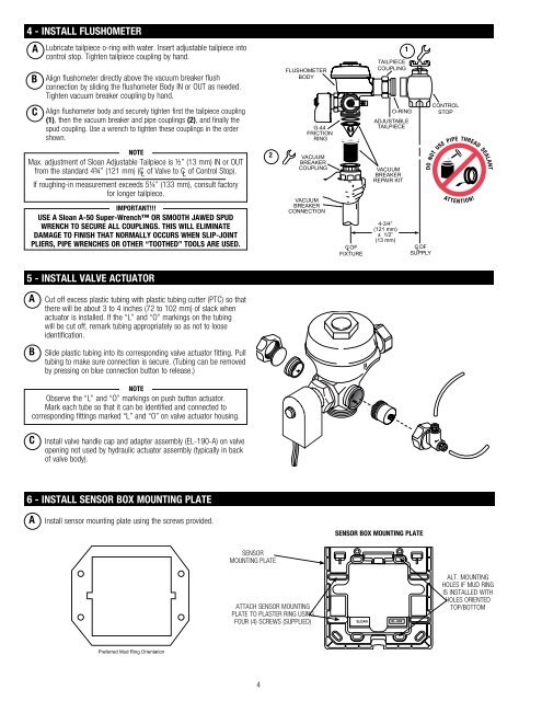
4 - INSTALL FLUSHOMETER<br />
A<br />
C<br />
Lubricate tailpiece o-ring with water. Insert adjustable tailpiece into<br />
control stop. Tighten tailpiece coupling by hand.<br />
B Align flushometer directly above the vacuum breaker flush<br />
connection by sliding the flushometer Body IN or OUT as needed.<br />
Tighten vacuum breaker coupling by hand.<br />
Align flushometer body and securely tighten first the tailpiece coupling<br />
(1), then the vacuum breaker and pipe couplings (2), and finally the<br />
spud coupling. Use a wrench to tighten these couplings in the order<br />
shown.<br />
FLUSHOMETER<br />
BODY<br />
G-44<br />
FRICTION<br />
RING<br />
1<br />
TAILPIECE<br />
COUPLING<br />
O-RING<br />
ADJUSTABLE<br />
TAILPIECE<br />
CONTROL<br />
STOP<br />
NOTE<br />
Max. adjustment of <strong>Sloan</strong> Adjustable Tailpiece is ½” (13 mm) IN or OUT<br />
from the standard 4¾” (121 mm) (C L of <strong>Valve</strong> to C L of Control Stop).<br />
If roughing-in measurement exceeds 5¼” (133 mm), consult factory<br />
for longer tailpiece.<br />
IMPORTANT!!!<br />
USE A <strong>Sloan</strong> A-50 Super-Wrench OR SMOOTH JAWED SPUD<br />
WRENCH TO SECURE ALL COUPLINGS. THIS WILL ELIMINATE<br />
DAMAGE TO FINISH THAT NORMALLY OCCURS WHEN SLIP-JOINT<br />
PLIERS, PIPE WRENCH<strong>ES</strong> OR OTHER “TOOTHED” TOOLS ARE USED.<br />
2<br />
VACUUM<br />
BREAKER<br />
COUPLING<br />
VACUUM<br />
BREAKER<br />
CONNECTION<br />
C L OF<br />
FIXTURE<br />
VACUUM<br />
BREAKER<br />
REPAIR KIT<br />
4-3/4”<br />
(121 mm)<br />
± 1/2”<br />
(13 mm)<br />
C L OF<br />
SUPPLY<br />
5 - INSTALL VALVE ACTUATOR<br />
A<br />
B<br />
Cut off excess plastic tubing with plastic tubing cutter (PTC) so that<br />
there will be about 3 to 4 inches (72 to 102 mm) of slack when<br />
actuator is installed. If the “L” and “O” markings on the tubing<br />
will be cut off, remark tubing appropriately so as not to loose<br />
identification.<br />
Slide plastic tubing into its corresponding valve actuator fitting. Pull<br />
tubing to make sure connection is secure. (Tubing can be removed<br />
by pressing on blue connection button to release.)<br />
NOTE<br />
Observe the “L” and “O” markings on push button actuator.<br />
Mark each tube so that it can be identified and connected to<br />
corresponding fittings marked “L” and “O” on valve actuator housing.<br />
C<br />
Install valve handle cap and adapter assembly (EL-190-A) on valve<br />
opening not used by hydraulic actuator assembly (typically in back<br />
of valve body).<br />
6 - INSTALL SENSOR BOX MOUNTING PLATE<br />
A<br />
Install sensor mounting plate using the screws provided.<br />
SENSOR BOX MOUNTING PLATE<br />
SENSOR<br />
MOUNTING PLATE<br />
ATTACH SENSOR MOUNTING<br />
PLATE TO PLASTER RING USING<br />
FOUR (4) SCREWS (SUPPLIED)<br />
ALT. MOUNTING<br />
HOL<strong>ES</strong> IF MUD RING<br />
IS INSTALLED WITH<br />
HOL<strong>ES</strong> ORIENTED<br />
TOP/BOTTOM<br />
Preferred Mud Ring Orientation<br />
4