How real electric motors work - School of Physics - The University of ...
How real electric motors work - School of Physics - The University of ...
How real electric motors work - School of Physics - The University of ...

Create successful ePaper yourself
Turn your PDF publications into a flip-book with our unique Google optimized e-Paper software.
UNIVERSITY OF NEW SOUTH WALES - SYDNEY - AUSTRALIA<br />
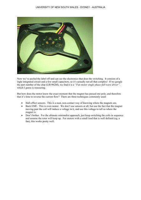
Now we’ve peeled the label <strong>of</strong>f and can see the electronics that does the switching. It consists <strong>of</strong> a<br />
ingle integrated circuit and a few small capacitors, so it’s actually not all that complex! If we google<br />
the part number <strong>of</strong> the chip (LB1962M), we find it is a “Fan motor single phase full-wave driver”,<br />
which I guess is reassuring.<br />
But how does the motor know the exact moment that the magnet has passed one pole, and therefore<br />
that it’s time to reverse the current flow? <strong>The</strong>re are three techniques commonly used:<br />
• Hall-effect sensors. This is a neat, non-contact way <strong>of</strong> knowing where the magnets are.<br />
• Back EMF. This is even neater. We don’t use sensors at all, but use the fact that the magnet<br />
moving past the coil will induce a voltage in it, and use this voltage to tell us where the<br />
magnet is.<br />
• Don’t bother. For the ultimate minimalist approach, just keep switching the coils in sequence<br />
and assume the rotor will keep up. For <strong>motors</strong> with a small load that is well defined (eg, a<br />
fan), this <strong>work</strong>s pretty well.