How real electric motors work - School of Physics - The University of ...
How real electric motors work - School of Physics - The University of ...
How real electric motors work - School of Physics - The University of ...

You also want an ePaper? Increase the reach of your titles
YUMPU automatically turns print PDFs into web optimized ePapers that Google loves.
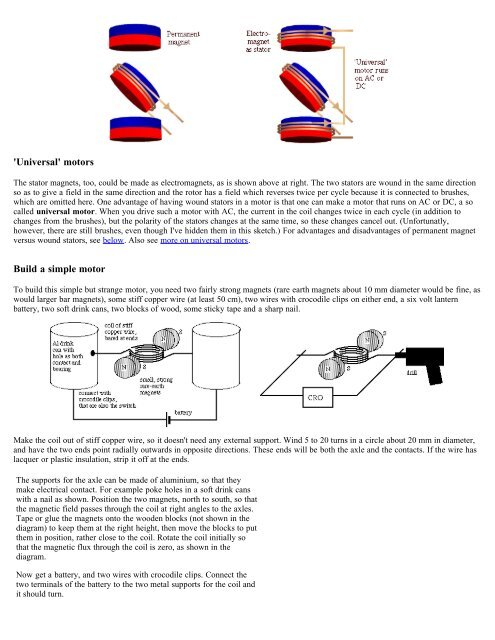
'Universal' <strong>motors</strong><br />
<strong>The</strong> stator magnets, too, could be made as electromagnets, as is shown above at right. <strong>The</strong> two stators are wound in the same direction<br />
so as to give a field in the same direction and the rotor has a field which reverses twice per cycle because it is connected to brushes,<br />
which are omitted here. One advantage <strong>of</strong> having wound stators in a motor is that one can make a motor that runs on AC or DC, a so<br />
called universal motor. When you drive such a motor with AC, the current in the coil changes twice in each cycle (in addition to<br />
changes from the brushes), but the polarity <strong>of</strong> the stators changes at the same time, so these changes cancel out. (Unfortunatly,<br />
however, there are still brushes, even though I've hidden them in this sketch.) For advantages and disadvantages <strong>of</strong> permanent magnet<br />
versus wound stators, see below. Also see more on universal <strong>motors</strong>.<br />
Build a simple motor<br />
To build this simple but strange motor, you need two fairly strong magnets (rare earth magnets about 10 mm diameter would be fine, as<br />
would larger bar magnets), some stiff copper wire (at least 50 cm), two wires with crocodile clips on either end, a six volt lantern<br />
battery, two s<strong>of</strong>t drink cans, two blocks <strong>of</strong> wood, some sticky tape and a sharp nail.<br />
Make the coil out <strong>of</strong> stiff copper wire, so it doesn't need any external support. Wind 5 to 20 turns in a circle about 20 mm in diameter,<br />
and have the two ends point radially outwards in opposite directions. <strong>The</strong>se ends will be both the axle and the contacts. If the wire has<br />
lacquer or plastic insulation, strip it <strong>of</strong>f at the ends.<br />
<strong>The</strong> supports for the axle can be made <strong>of</strong> aluminium, so that they<br />
make <strong>electric</strong>al contact. For example poke holes in a s<strong>of</strong>t drink cans<br />
with a nail as shown. Position the two magnets, north to south, so that<br />
the magnetic field passes through the coil at right angles to the axles.<br />
Tape or glue the magnets onto the wooden blocks (not shown in the<br />
diagram) to keep them at the right height, then move the blocks to put<br />
them in position, rather close to the coil. Rotate the coil initially so<br />
that the magnetic flux through the coil is zero, as shown in the<br />
diagram.<br />
Now get a battery, and two wires with crocodile clips. Connect the<br />
two terminals <strong>of</strong> the battery to the two metal supports for the coil and<br />
it should turn.