How real electric motors work - School of Physics - The University of ...
How real electric motors work - School of Physics - The University of ...
How real electric motors work - School of Physics - The University of ...

You also want an ePaper? Increase the reach of your titles
YUMPU automatically turns print PDFs into web optimized ePapers that Google loves.
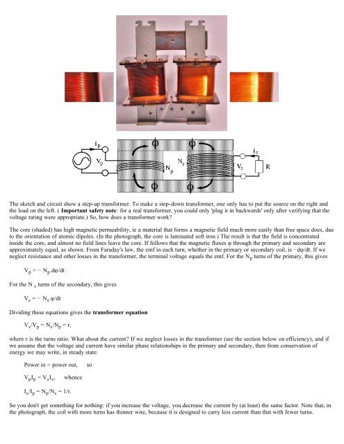
<strong>The</strong> sketch and circuit show a step-up transformer. To make a step-down transformer, one only has to put the source on the right and<br />
the load on the left. ( Important safety note: for a <strong>real</strong> transformer, you could only 'plug it in backwards' only after verifying that the<br />
voltage rating were appropriate.) So, how does a transformer <strong>work</strong>?<br />
<strong>The</strong> core (shaded) has high magnetic permeability, ie a material that forms a magnetic field much more easily than free space does, due<br />
to the orientation <strong>of</strong> atomic dipoles. (In the photograph, the core is laminated s<strong>of</strong>t iron.) <strong>The</strong> result is that the field is concentrated<br />
inside the core, and almost no field lines leave the core. If follows that the magnetic fluxes φ through the primary and secondary are<br />
approximately equal, as shown. From Faraday's law, the emf in each turn, whether in the primary or secondary coil, is −dφ/dt. If we<br />
neglect resistance and other losses in the transformer, the terminal voltage equals the emf. For the N p turns <strong>of</strong> the primary, this gives<br />
V p = − N p .dφ/dt .<br />
For the N s turns <strong>of</strong> the secondary, this gives<br />
V s = − N s .φ/dt<br />
Dividing these equations gives the transformer equation<br />
V s /V p = N s /N p = r.<br />
where r is the turns ratio. What about the current? If we neglect losses in the transformer (see the section below on efficiency), and if<br />
we assume that the voltage and current have similar phase relationships in the primary and secondary, then from conservation <strong>of</strong><br />
energy we may write, in steady state:<br />
Power in = power out,<br />
so<br />
V p I p = V s I s ,<br />
whence<br />
I s /I p = N p /N s = 1/r.<br />
So you don't get something for nothing: if you increase the voltage, you decrease the current by (at least) the same factor. Note that, in<br />
the photograph, the coil with more turns has thinner wire, because it is designed to carry less current than that with fewer turns.