Surgical Technique
Surgical Technique
Surgical Technique

You also want an ePaper? Increase the reach of your titles
YUMPU automatically turns print PDFs into web optimized ePapers that Google loves.
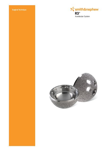
<strong>Surgical</strong> <strong>Technique</strong>
Design surgeon list<br />
Smith & Nephew thanks the following surgeons for their<br />
participation as part of the R3 system design team:<br />
Robert Barrack, MD<br />
St. Louis, Missouri<br />
Robert Bourne, MD<br />
London Health Sciences Center<br />
London, Ontario, Canada<br />
Jonathan Garino, MD<br />
University of Pennsylvania<br />
School of Medicine<br />
Philadelphia, Pennsylvania<br />
Wayne M. Goldstein, MD<br />
Clinical Professor of Orthopaedics<br />
University of Illinois at Chicago<br />
Illinois Bone and Joint Institute<br />
Richard Kyle, MD<br />
Minneapolis, Minnesota<br />
Stephen J. McMahon MB, BS,<br />
FRACS(Orth), FA(Orth)A<br />
Senior Lecturer Monash University<br />
Malabar Orthopaedic Clinic<br />
Melbourne, Australia<br />
John L. Masonis, MD<br />
OrthoCarolina<br />
Hip & Knee Center<br />
Charlotte, North Carolina<br />
Henrik Malchau, MD<br />
Associate Professor Harvard Medical School<br />
Co-director The Harris Orthopaedic<br />
Biomechanics and Biomaterials Laboratory<br />
Massachusetts General Hospital<br />
Boston, Massachusetts<br />
Michael Ries, MD<br />
University of California<br />
San Francisco, California<br />
Cecil Rorabeck, MD<br />
Professor of Orthopaedic Surgery<br />
University of Western Ontario<br />
London, Ontario, Canada<br />
Nota Bene: This technique description herein is made available to the healthcare professional to illustrate the author’s<br />
suggested treatment for the uncomplicated procedure. In the final analysis, the preferred treatment is that which<br />
addresses the needs of the patient.<br />
2
Short technique<br />
Preoperative Planning<br />
Acetabular Reaming<br />
Acetabular Trialing<br />
Acetabular Shell Insertion<br />
Acetabular Screw Insertion<br />
Acetabular Poly Liner Insertion<br />
3
Preoperative planning<br />
Preoperative X-rays should include an AP of the<br />
pelvis centered over the symphysis and an AP<br />
and lateral of the affected hip.<br />
Templating can be done on the affected side, but<br />
it is important that the contralateral hip also be<br />
templated to verify the size.<br />
To ensure a congruent fit, the acetabular<br />
component should be medialized to the medial<br />
aspect of the acetabulum, as indicated by the<br />
teardrop.<br />
The center of rotation also should be marked for<br />
subsequent reference.<br />
4
Acetabular exposure<br />
Complete exposure of the acetabulum is<br />
required, regardless of the type of approach.<br />
Use the approach with which you are most<br />
familiar and achieve the best surgical results.<br />
First, resect the acetabular labrum and place a<br />
blunt retractor anteriorly.<br />
After identifying the transverse acetabular<br />
ligament, place a blunt retractor around the<br />
inferior margin of the acetabulum.<br />
Depending on the exposure, a third retractor<br />
can be placed posteriorly following the excision<br />
of the labrum.<br />
<strong>Surgical</strong> tips:<br />
• To minimize the need of assistance,<br />
each of the acetabular retractors can<br />
be tied directly to a charnley retractor.<br />
• Dividing the transverse acetabular<br />
ligament will allow reaming to begin<br />
inferiorly, preventing the tendency of the<br />
reamer to migrate superiorly.<br />
• Removal of soft tissue and overhanging<br />
osteophytes from the foveal notch aids<br />
visualization of the quadralateral plate<br />
and the depth that the acetabulum<br />
should be reamed.<br />
Remove all overhanging soft tissue and<br />
osteophytes in order to visualize the entire<br />
acetabular socket.<br />
The acetabulum should be medialized to<br />
restore the normal center of hip rotation.<br />
5
Acetabular reaming<br />
Select an acetabular reamer that is considerably<br />
smaller than the templated size of the cup.<br />
Generally, reaming 6–8mm lower than<br />
thetemplated size is suitable.<br />
Position the initial reamer in a vertical direction (1)<br />
to ensure the reamer is taken down to the<br />
medial wall.<br />
Direct the second reamer and all subsequent<br />
reamers in approximately 45° of abduction and<br />
20° of anteversion for final position of the<br />
acetabular component. (2)<br />
Preserve subchondral bone to provide good<br />
support for the prosthesis. This might mean the<br />
reamer will not be medialized all the way to the<br />
inner wall. One might suggest leaving some<br />
remaining subchondral bone and removing the<br />
medial bone that is osteophyte and is covering<br />
fatty tissue.<br />
Frequently palpate the posterior and anterior walls<br />
of the acetabulum during the reaming process as<br />
these walls will determine the largest acetabular<br />
size that can be accommodated. Avoid allowing<br />
the reamer to drift posteriorly where the bone<br />
might be less dense and the path of least<br />
resistance for the reamer.<br />
To press-fit the THREE HOLE and NO HOLE cups,<br />
the acetabulum should be underreamed by 1–<br />
2mm depending on bone quality and acetabular<br />
size. The cups are available in even sizes so the<br />
last reamer used should either be an odd size for<br />
1mm or an even size for 2mm underreaming.<br />
<strong>Surgical</strong> tips:<br />
• Each successive reamer must be fully<br />
seated within the acetabulum. Failure to<br />
do so will result in lateralization of the<br />
trial and exposure of the porous<br />
coating. If lateralization occurs, go back<br />
to a smaller reamer and begin again,<br />
checking each size to ensure that the<br />
reamers are fully seated.<br />
• Increasing the reamer size by 2mm is<br />
recommended, although in smaller<br />
patients 1mm increments may be<br />
preferred.<br />
• Mark the medial wall with an<br />
electrocautery prior to using the last<br />
reamer. If the last reamer does not<br />
remove the mark, repeat reaming,<br />
dropping back a size if necessary.<br />
Instrument tips:<br />
• The acetabular reamer has an open<br />
back, which helps visualize reaming<br />
and allows easy access to bone chips.<br />
This style of reamer is hemispherical<br />
and when fully seated it should be<br />
covered by the rim of the acetabulum.<br />
• Gently rock reamer handle back and<br />
forth approximately 5° for last size used<br />
only to ensure rim is accurate for the<br />
desired press-fit.<br />
6
Acetabular trialing<br />
After the preparation of the acetabulum, the trial<br />
shell should be inserted to verify size and position<br />
of the cup. The surgeon should note the<br />
appropriate orientation of the acetabular trial to<br />
position the cup correctly.<br />
A trial liner insert cannot be inserted into a trial<br />
shell for trial reduction.<br />
If trial reduction using a trial insert is desired at<br />
this time, then the preparation of the femur should<br />
occur up until the trial reduction stage. The<br />
surgeon then has the option of inserting a trial<br />
acetabular liner (preferred) in the acetabular<br />
implant for subsequent leg length, offset and<br />
stability assessments or the real acetabular insert.<br />
<strong>Surgical</strong> tip:<br />
• The bone at the edge of the trial shell<br />
can be marked with an electric cautery<br />
to help in final component positioning.<br />
Instrument tip:<br />
• The trial shells are the exact size<br />
specified. They can be used to assess<br />
the accuracy of reaming or can be<br />
press-fit into the acetabulum if using a<br />
larger size than the final reamer.<br />
7
Acetabular shell insertion<br />
Select the appropriate acetabular implant, attach<br />
the shell to the cup positioner/impactor and insert<br />
it into the acetabulum.<br />
Rotate the X-bar shaft so that it is in line with the<br />
liner removal slot. For the THREE HOLE cup this<br />
positions the three holes in the superior direction.<br />
Position the X-bar so that the vertical bar is<br />
perpendicular to the long axis of the body and the<br />
appropriate crossbar (left or right) aligns with the<br />
long axis of the body.<br />
Firmly tap the inserter with a mallet until the cup<br />
is fully seated.<br />
Gently toggle the impactor handle to assess the<br />
stability and contact of the shell.<br />
Remove the X-bar, then disengage the impactor<br />
handle and look through the impactor hole to<br />
judge the distance between the medial wall and<br />
the shell.<br />
<strong>Surgical</strong> tips:<br />
• The change in pitch that occurs as the<br />
shell is seated against the medial wall<br />
is often audible. A depth gauge can be<br />
inserted through the screw holes and<br />
apex hole to determine the adequacy<br />
of shell seating.<br />
• The use of the slap hammer may be<br />
helpful in extracting the shell for<br />
repositioning.<br />
Instrument tips:<br />
• The plastic tip on the cup impactor is<br />
removable for cleaning.<br />
• The X-bar references 45° of abduction<br />
and 20° of anterversion.<br />
If the cup is firmly seated, there should be no gap<br />
between the shell and the medial wall and no<br />
apparent movement in the component.<br />
8<br />
Specific to shells for R3 acetabular ceramic<br />
liners:<br />
Proper range of motion is critical for implant<br />
longevity. If any repositioning of the shell is<br />
required, it should only be performed using the<br />
shell positioner. Any use of a punch, osteotome<br />
or other instrument on the shell’s rim could result<br />
in damage to the taper section and compromise<br />
the integrity of the shell and ceramic liner mating<br />
and lead to liner fracture. It is important to protect<br />
the shell’s rim and inner taper from any damage<br />
during implantation.
Acetabular screw insertion<br />
Screw fixation is simple, fast and the most<br />
common method of assuring additional fixation.<br />
Acetabular screws work in compression,<br />
which allows the shell to fully seat in the<br />
acetabular cavity.<br />
For screw fixation, each screw hole must be<br />
predrilled. Using the variable angle drill guide,<br />
adjust the angle of the tip to align with the<br />
selected screw hole and press firmly in the shell.<br />
After drilling the hole, use the depth gauge to<br />
verify appropriate screw length(s).<br />
<strong>Surgical</strong> tip:<br />
• Screws have been shown to be a reliable<br />
method of assuring fixation; however, it<br />
is important to avoid neurovascular<br />
complications by proper screw<br />
placement, avoiding the anterior/superior<br />
or anterior/inferior quadrants.<br />
Use the screw forceps to hold the screw. Attach<br />
the ball-joint or flexible screwdriver shaft to the<br />
end of the screw. Then introduce the screw into<br />
the hole and screw it into place using the<br />
ratcheting screwdriver handle. Make sure the<br />
screw is fully seated within the screw hole so that<br />
it will not impinge on the acetabular shell/liner.<br />
9
R3 Acetabular Liner insertion<br />
A trial reduction should be performed with the<br />
final shell and broach in place to appropriately<br />
assess head length, stem offset, liner style and<br />
position. Use of ‘skirted’ modular heads should be<br />
avoided when possible to maximize range of<br />
motion to impingement.<br />
Before inserting the R3 acetabular liner, lavage<br />
any unused holes and insert the hole covers.<br />
Using the angled hole cover inserter, place screw<br />
hole covers over any remaining screw holes and<br />
then impact with the peg impactor. Cover the<br />
apex hole with the threaded hole cover. Using the<br />
straight screwdriver, screw in the hole cover until<br />
it stops and is flush with the inner diameter of the<br />
shell. Insert heard bearings only after ensuring<br />
the inner taper of the shell is clean and dry.<br />
For liner insertion, screw the appropriate sized<br />
liner impactor head on the end of the cup<br />
impactor handle and ensure that the tabs on<br />
the liner are aligned with the indentions in the<br />
shell. Impact firmly with the mallet until the liner<br />
is fully seated.<br />
Inspect the liner/shell interface for proper seating.<br />
The liner should sit flush with the face of the shell.<br />
<strong>Surgical</strong> tips:<br />
• Running a finger around the<br />
circumference of the shell and a visual<br />
check will help determine if the liner<br />
is flush with the shell face.<br />
• The XLPE liner requires an impaction<br />
force between 60 and 120 pounds,<br />
increasing with the diameter of the shell.<br />
• The XLPE & CoCr liners can be removed<br />
and repositioned once without<br />
compromising the locking mechanism of<br />
the liner. To remove R3 liners, insert the<br />
liner removal tool fully into the removal<br />
slot and pry the liner loose.<br />
Instrument tips:<br />
• The liner trials are designed with flexible<br />
locking tabs around the periphery that<br />
is a quick-snap design. The trial liners<br />
are removed with the trial liner removal<br />
tool via the removal slot at the apex of<br />
the trial liner and a clockwise twist of<br />
the removal tool.<br />
10
R3 Acetabular Liner insertion continued<br />
R3 Hard Bearing Insertion<br />
R3 Hard Bearings come preassembled with a<br />
disposable single-use hard bearing alignment<br />
guide. The liner/alignment guide assembly is then<br />
introduced by hand and sits flush on the face of<br />
the shell. The liner must be checked for proper<br />
orientation. Verification of proper liner seating in<br />
the shell should be confirmed by both a visual<br />
check to see that the insertion ring is sitting on<br />
the shell face and a manual check with the<br />
fingers to feel that the ring does not rock on the<br />
face of the shell. Do not impact the liner if it is not<br />
oriented properly, as this can damage the shell<br />
and/or locking mechanism. Once orientation has<br />
been confirmed, impact the liner into place using<br />
the appropriate sized liner impactor head placed<br />
on the shell positioner/impactor. Once impacted,<br />
the alignment guide will disengage onto the shell<br />
positioner/impactor and should be removed at<br />
that time.*<br />
<strong>Surgical</strong> tip:<br />
• It may prove helpful to rotate the<br />
liner/guide slightly to ensure soft tissues<br />
and osteophytes are clear.<br />
• The metal liner can be removed by<br />
placing the liner removal tool in the<br />
removal slot and prying, or impacting<br />
and prying if necessary, the liner loose.<br />
*Cautionary Statement<br />
Be sure to remove the disposable hard bearing<br />
alignment guide. It is not intended for implantation.<br />
In the event that the hard bearing alignment guide<br />
is disengaged from the liner, the alignment guide<br />
should be reassembled to the liner before<br />
implantation. This is accomplished by taking the<br />
disposable alignment guide and placing it upside<br />
down on the back table. The liner can then be<br />
placed upside down on the alignment guide such<br />
that the peripheral rim is sitting on the alignment<br />
guide. Simply push the liner onto the guide until<br />
the insertion ring locks snugly on the liner. The<br />
assembly is ready for placement in the shell.<br />
11
R3 AcetabularLiner insertion continued<br />
Specific to R3 metal liners<br />
The R3 metal liner and R3 shell must be used with<br />
either Smith & Nephew BHR resurfacing femoral<br />
heads or Smith & Nephew BHR Modular heads.<br />
Do not mix the CoCr head or liners with any other<br />
manufacturer’s acetabular shell or stem<br />
respectively. Use the appropriate size head and<br />
liner only. A sizing mismatch may result in<br />
premature implant failure.<br />
Specific to R3 ceramic liners<br />
Use extreme care in handling and storage of<br />
ceramic implant components. Damage to<br />
components may induce internal stresses that are<br />
not obvious to the observer, and it may lead to<br />
premature failure of the component. Before use of<br />
ceramic implants, carefully examine each<br />
component for indications of damage that may<br />
have occurred during shipping or prior in-hospital<br />
handling. All surfaces should be smooth without<br />
pitting, scratches or other surface irregularities.<br />
<strong>Surgical</strong> tips:<br />
• Should a correction or revision of a R3<br />
ceramic liner be necessary, a new R3<br />
ceramic insert must be used.<br />
• The ceramic liner can be removed by<br />
placing the liner removal tool in the<br />
removal slot and prying (or impacting if<br />
necessary) the liner loose.<br />
Only Smith & Nephew ceramic femoral heads can<br />
be used with the R3 ceramic acetabular liners. Do<br />
not mix the ceramic liner or ceramic head with<br />
any other manufacturer’s acetabular shell or stem,<br />
respectively. Use the appropriate size head and<br />
liner only. A sizing mismatch may result in<br />
premature implant failure. Once the liner or the<br />
head are impacted, the ridges machined into the<br />
metal taper deform. If, for any reason, the ceramic<br />
femoral head is removed, the metal stem taper<br />
cannot be reused with a ceramic component. If<br />
the R3 ceramic liner is removed, a new R3<br />
ceramic liner must be used.<br />
12
Hard bearing liner insertion<br />
1<br />
2<br />
3<br />
4<br />
13
Shell and liner offerings<br />
XLPE<br />
Ceramic<br />
Metal<br />
cups<br />
22 28 32 36<br />
32 36<br />
38 40 42 44 46 48 50 52 54<br />
40<br />
42<br />
44<br />
46<br />
48<br />
50<br />
52<br />
54<br />
56<br />
58<br />
60<br />
62<br />
64<br />
66/68<br />
Range of motion<br />
(SPECTRON stem (size 3), +4 head offset)<br />
REFLECTION Hip System<br />
22mm 28mm 32mm 36mm<br />
0º 143º 142º 145º 148º<br />
20º 122º 122º 126º 128º<br />
Ceramic — 136º 141º —<br />
R3 Acetabular System<br />
22mm 28mm 32mm 36mm<br />
0º 140º 150º 154º 157º<br />
20º 132º 134º 136º 138º<br />
Ceramic — — 154º 156º<br />
14
Poly thickness chart<br />
Shell OD<br />
Poly ID<br />
Poly<br />
Thickness<br />
Taper<br />
Region mm<br />
40 22 5.5 6.1<br />
42 22 6.5 7.1<br />
44 22 7.5 8.1<br />
46 28 5.4 6.1<br />
48 28 6.4 7.1<br />
48 32 4.3 5.1<br />
50 28 7.3 8.1<br />
50 32 5.3 6.1<br />
52 28 8.3 9.1<br />
52 32 6.3 7.1<br />
52 36 4.3 5.1<br />
54 28 9.3 10.1<br />
54 32 7.3 8.1<br />
54 36 5.3 6.1<br />
56 28 10.3 11.1<br />
56 32 8.3 9.1<br />
56 36 6.3 7.1<br />
58 28 11.3 12.1<br />
58 32 9.3 10.1<br />
58 36 7.3 8.1<br />
60 28 12.3 13.1<br />
60 32 10.3 11.1<br />
60 36 8.3 9.1<br />
62 32 11.3 12.1<br />
62 36 9.3 10.1<br />
64 36 10.3 11.1<br />
66–68 36 11.3 12.1<br />
Poly<br />
Thickness<br />
Load<br />
Bearing<br />
Region mm<br />
Taper<br />
region<br />
Load<br />
bearing<br />
15
Catalog<br />
R3 NO HOLE Acetabular Shells<br />
Standard size shells<br />
Small size shells<br />
Cat. no. ODmm Cat. no. ODmm<br />
7133-1846 46 7133-1840 40<br />
7133-1848 48 7133-1842 42<br />
7133-1850 50 7133-1844 44<br />
7133-1852 52<br />
7133-1854 54 Large shell sizes<br />
7133-1856 56 7133-1866 66<br />
7133-1858 58 7133-1868 68<br />
7133-1860 60<br />
7133-1862 62<br />
7133-1864 64<br />
R3 NO HOLE HA Acetabular Shells<br />
Standard size shells<br />
Small size shells<br />
Cat. no. ODmm Cat. no. ODmm<br />
7133-2246 46 7133-2240 40<br />
7133-2248 48 7133-2242 42<br />
7133-2250 50 7133-2244 44<br />
7133-2252 52<br />
7133-2254 54 Large shell sizes<br />
7133-2256 56 7133-2266 66<br />
7133-2258 58 7133-2268 68<br />
7133-2260 60<br />
7133-2262 62<br />
7133-2264 64<br />
R3 THREE HOLE Acetabular Shells<br />
Standard size shells<br />
Small size shells<br />
Cat. no. ODmm Cat. no. ODmm<br />
7133-5546 46 7133-5540 40<br />
7133-5548 48 7133-5542 42<br />
7133-5550 50 7133-5544 44<br />
7133-5552 52<br />
7133-5554 54 Large shell sizes<br />
7133-5556 56 7133-5566 66<br />
7133-5558 58 7133-5568 68<br />
7133-5560 60<br />
7133-5562 62<br />
7133-5564 64<br />
R3 THREE HOLE HA Acetabular Shells<br />
Standard size shells<br />
Small size shells<br />
Cat. no. ODmm Cat. no. ODmm<br />
7133-1946 46 7133-1940 40<br />
7133-1948 48 7133-1942 42<br />
7133-1950 50 7133-1944 44<br />
7133-1952 52<br />
7133-1954 54 Large shell sizes<br />
7133-1956 56 7133-1966 66<br />
7133-1958 58 7133-1968 68<br />
7133-1960 60<br />
7133-1962 62<br />
7133-1964 64<br />
16
Catalog<br />
R3 XLPE Acetabular Liners<br />
ID OD 0° XLPE Liner 20° XLPE Liner 0° +4 XLPE Liner 20°+4 XLPE Liner<br />
Cat. no. Cat. no. Cat. no. Cat. no.<br />
22 40 7133-4840 7133-4940 7133-5840 7133-7140<br />
22 42 7133-4842 7133-4942 7133-5842 7133-7142<br />
22 44 7133-4844 7133-4944 7133-5844 7133-7144<br />
28 46 7133-7546 7133-4946 7133-5946 7133-7746<br />
28 48 7133-7548 7133-4948 7133-5948 7133-7748<br />
28 50 7133-7550 7133-4950 7133-5950 7133-7750<br />
28 52 7133-7552 7133-4952 7133-5952 7133-7752<br />
28 54 7133-7554 7133-4954 7133-5954 7133-7754<br />
28 56 7133-7556 7133-4956 7133-5956 7133-7756<br />
28 58 7133-7558 7133-4958 7133-5958 7133-7758<br />
28 60 7133-7560 7133-4960 7133-5960 7133-7760<br />
32 48 7133-9548 7133-7648 7133-6648 7133-7948<br />
32 50 7133-9550 7133-7650 7133-6650 7133-7950<br />
32 52 7133-9552 7133-7652 7133-6652 7133-7952<br />
32 54 7133-9554 7133-7654 7133-6654 7133-7954<br />
32 56 7133-9556 7133-7656 7133-6656 7133-7956<br />
32 58 7133-9558 7133-7658 7133-6658 7133-7958<br />
32 60 7133-9560 7133-7660 7133-6660 7133-7960<br />
32 62 7133-9562 7133-7662 7133-6662 7133-7962<br />
36 52 7133-2752 7133-5752 7133-6952 7133-8552<br />
36 54 7133-2754 7133-5754 7133-6954 7133-8554<br />
36 56 7133-2756 7133-5756 7133-6956 7133-8556<br />
36 58 7133-2758 7133-5758 7133-6958 7133-8558<br />
36 60 7133-2760 7133-5760 7133-6960 7133-8560<br />
36 62 7133-2762 7133-5762 7133-6962 7133-8562<br />
36 64 7133-2764 7133-5764 7133-6964 7133-8564<br />
36 66/68 7133-2766 7133-5766 7133-6966 7133-8566<br />
17
Catalog<br />
R3 INTL Forte Ceramic Liners*<br />
ID OD Ceramic<br />
Cat. no.<br />
32 48 7133-1648<br />
32 50 7133-1650<br />
36 52 7133-1652<br />
36 54 7133-1654<br />
36 56 7133-1656<br />
36 58 7133-1658<br />
36 60 7133-1660<br />
36 62 7133-1662<br />
36 64 7133-1664<br />
36 66/68 7133-1666<br />
R3 INTL Delta Ceramic Liners**<br />
ID OD Ceramic<br />
Cat. no.<br />
32 48 7133-1748<br />
32 50 7133-1750<br />
36 52 7133-1752<br />
36 54 7133-1754<br />
36 56 7133-1756<br />
36 58 7133-1758<br />
36 60 7133-1760<br />
36 62 7133-1762<br />
36 64 7133-1764<br />
36 66/68 7133-1766<br />
R3 INTL Metal Liners***<br />
ID OD CoCr<br />
Cat. no.<br />
38 50 7133-5850<br />
40 52 7133-5852<br />
42 54 7133-5854<br />
44 56 7133-5856<br />
46 58 7133-5858<br />
48 60 7133-5860<br />
50 62 7133-5862<br />
52 64 7133-5864<br />
54 66/68 7133-5866<br />
* For Use with Alumina Ceramic Heads Only<br />
** For Use with Delta Ceramic Heads Only<br />
*** For Use with BHR Modular or Resurfacing Heads Only<br />
May not be available at launch<br />
18
Catalog<br />
R3 Trial Shells<br />
Standard size trail shells<br />
Small size trial shells<br />
Cat. no. ODmm Cat. no. ODmm<br />
7136-0745 45 7136-0739 39<br />
7136-0746 46 7136-0740 40<br />
7136-0747 47 7136-0741 41<br />
7136-0748 48 7136-0742 42<br />
7136-0749 49 7136-0743 43<br />
7136-0750 50 7136-0744 44<br />
7136-0751 51<br />
7136-0752 52 Large size trial shells<br />
7136-0753 53 Cat. no. ODmm<br />
7136-0754 54 7136-0765 65<br />
7136-0755 55 7136-0766 66<br />
7136-0756 56 7136-0767 67<br />
7136-0757 57 7136-0768 68<br />
7136-0758 58<br />
7136-0759 59<br />
7136-0760 60<br />
7136-0761 61<br />
7136-0762 62<br />
7136-0763 63<br />
7136-0764 64<br />
R3 Poly Snap in Trial Liners<br />
ID OD 0° Trial 20° Trial 0° +4 Trial 20°+4 Trial<br />
Cat. no. Cat. no. Cat. no. Cat. no.<br />
22 40 7136-0540 7136-5340 7136-6140 7136-8640<br />
22 42 7136-0542 7136-5342 7136-6142 7136-8642<br />
22 44 7136-0544 7136-5344 7136-6144 7136-8644<br />
28 46 7136-0546 7136-6446 7136-8346 7136-8746<br />
28 48 7136-0548 7136-6448 7136-8348 7136-8748<br />
28 50 7136-0550 7136-6450 7136-8350 7136-8750<br />
28 52 7136-0552 7136-6452 7136-8352 7136-8752<br />
28 54 7136-0554 7136-6454 7136-8354 7136-8754<br />
28 56 7136-0556 7136-6456 7136-8356 7136-8756<br />
28 58 7136-0558 7136-6458 7136-8358 7136-8758<br />
28 60 7136-0560 7136-6460 7136-8360 7136-8760<br />
32 48 7136-5148 7136-6548 7136-8448 7136-8848<br />
32 50 7136-5150 7136-6550 7136-8450 7136-8850<br />
32 52 7136-5152 7136-6552 7136-8452 7136-8852<br />
32 54 7136-5154 7136-6554 7136-8454 7136-8854<br />
32 56 7136-5156 7136-6556 7136-8456 7136-8856<br />
32 58 7136-5158 7136-6558 7136-8458 7136-8858<br />
32 60 7136-5160 7136-6560 7136-8460 7136-8860<br />
32 62 7136-5162 7136-6562 7136-8462 7136-8862<br />
36 52 7136-5252 7136-7952 7136-8552 7136-9152<br />
36 54 7136-5254 7136-7954 7136-8554 7136-9154<br />
36 56 7136-5256 7136-7956 7136-8556 7136-9156<br />
36 58 7136-5258 7136-7958 7136-8558 7136-9158<br />
36 60 7136-5260 7136-7960 7136-8560 7136-9160<br />
36 62 7136-5262 7136-7962 7136-8562 7136-9162<br />
36 64 7136-5264 7136-7964 7136-8564 7136-9164<br />
36 66/68 7136-5266 7136-7966 7136-8566 7136-9166<br />
19
Catalog<br />
R3 Ceramic Snap in Trial Liners<br />
ID OD Ceramic Trial<br />
Cat. no.<br />
32 48 7136-9748<br />
32 50 7136-9750<br />
36 52 7136-9752<br />
36 54 7136-9754<br />
36 56 7136-9756<br />
36 58 7136-9758<br />
36 60 7136-9760<br />
36 62 7136-9762<br />
36 64 7136-9764<br />
36 66/68 7136-9766<br />
R3 Metal Snap in Trial Liners<br />
ID OD CoCr Trial<br />
Cat. no.<br />
38 50 7136-9450<br />
40 52 7136-9452<br />
42 54 7136-9454<br />
44 56 7136-9456<br />
46 58 7136-9458<br />
48 60 7136-9460<br />
50 62 7136-9462<br />
52 64 7136-9464<br />
54 66/68 7136-9466<br />
R3 Liner Impactor Heads<br />
Cat. no. Size mm<br />
7136-8122 22<br />
7136-8128 28<br />
7136-8132 32<br />
7136-8136 36<br />
7136-3842 38-42<br />
7136-4448 44-48<br />
7136-4449 50-54<br />
R3 MIS Instruments<br />
Cat. no. Description<br />
7136-8569 Offset Shell Impactor<br />
7136-6052 Offset X-Bar<br />
7136-3077 Offset Impactor Tip<br />
7136-4073 Offset Reamer Handle<br />
20
Catalog<br />
R3 Straight Shell Impactor<br />
Cat. no. 7136-4450<br />
R3 Impactor Replacement Tip<br />
Cat. no. 7136-8570<br />
R3 Depth Guage<br />
Cat. Nno. 7136-4451<br />
X-Bar<br />
Cat. no. MT-2201<br />
Screw Forceps<br />
Cat. no. 7136-2298<br />
Ball Joint Screwdriver<br />
Cat. no. 7136-2295<br />
R3 Variable Angle Drill Guide<br />
Cat. no. 7136-4477<br />
Reamer Handle<br />
Cat. no. 7136-2279<br />
Flexible Screw Drills<br />
Cat. no. Length mm<br />
7136-2915 15<br />
7136-2925 25<br />
7136-2935 35<br />
7136-2950 50<br />
Captured Flexible Screwdriver Shaft<br />
Cat. no. 7136-2291<br />
Captured U-Joint Screwdriver Shaft<br />
Cat. no. 7136-2292<br />
R3 <strong>Surgical</strong> Templates (not shown)<br />
Cat. no. 7136-1081<br />
21
Catalog<br />
R3 Trial Liner Removal Tool<br />
Cat. no. 7136-4455<br />
R3 Liner Removal Tool<br />
Cat. no. 7136-6021<br />
Hole Cover Impactor<br />
Cat. no. 73-2117<br />
Trial Shell Handle<br />
Cat. no. 7136-2297<br />
Flexible Screwdriver<br />
Cat. no. 7136-2290<br />
Ratchet Handle<br />
Cat. no. 7136-2294<br />
Small Slap Hammer<br />
Cat. no. 7136-7541<br />
REFLECTION Mallet<br />
Cat. no. 7136-2106<br />
Hole Cover Inserter<br />
Cat. no. 73-2133<br />
Straight Screwdriver Shaft<br />
Cat. no. 7136-2293<br />
Power Adaptors (not shown)<br />
Cat. no. 7136-2781<br />
7136-2782<br />
7136-2783<br />
22
Catalog<br />
Reamer Domes<br />
Standard size<br />
Small size<br />
Cat. no. Size mm Cat. no. Size mm<br />
7136-2742 42 7136-2738 38<br />
7136-2743 43 7136-2739 39<br />
7136-2744 44 7136-2740 40<br />
7136-2745 45 7136-2741 41<br />
7136-2746 46<br />
7136-2747 47 Large size<br />
7136-2748 48 Cat. no. Size mm<br />
7136-2749 49 7136-2765 65<br />
7136-2750 50 7136-2766 66<br />
7136-2751 51 7136-2767 67<br />
7136-2752 52 7136-2768 68<br />
7136-2753 53 7136-2769 69<br />
7136-2754 54 7136-2770 70<br />
7136-2755 55 7136-2771 71<br />
7136-2756 56 7136-2772 72<br />
7136-2757 57 7136-2773 73<br />
7136-2758 58 7136-2774 74<br />
7136-2759 59 7136-2775 75<br />
7136-2760 60 7136-2776 76<br />
7136-2761 61<br />
7136-2762 62<br />
7136-2763 63<br />
7136-2764 64<br />
23
Catalog<br />
Small Outer Case<br />
Cat. no. 7112-9401<br />
Lid for Outer Cases<br />
Cat. no. 7112-9402<br />
R3 Trial Liner Lid<br />
Cat. no. 7136-1081<br />
R3 Trial Shell Tray<br />
Cat. no. 7136-2213<br />
R3 20 Degree Trial Liner Tray<br />
Cat. no. 7136-1073<br />
R3 20 Degree +4 Trial Liner Tray<br />
Cat. no. 7136-1074<br />
R3 Metal Trial liner Tray<br />
Cat. no. 7136-2220<br />
R3 Jumbo Trial Liner Tray<br />
Cat. no. 7136-1076<br />
R3 0 Degree Outlier Tray<br />
Cat. no. 7136-1085<br />
R3 0 Degree +4 OutlierTray<br />
Cat. no. 7136-1084<br />
R3 Demo Sample Case<br />
Cat. no. 7138-4096<br />
R3 Main Instrument Tray<br />
Cat. no. 7136-2211<br />
R3 MIS Instrument Tray<br />
Cat. no. 7136-2219<br />
R3 Primary Reamer Dome Tray<br />
Cat. no. 7136-2212<br />
24
Catalog<br />
R3/REFLECTION Threaded<br />
Hole Cover<br />
Cat. no. 7133-6500<br />
Spherical Head Screws<br />
Cat. no. Length mm<br />
7133-2515 15<br />
7133-2520 20<br />
7133-2525 25<br />
7133-2530 30<br />
7133-2535 35<br />
7133-2540 40<br />
7133-2545 45<br />
7133-2550 50<br />
7133-2555 55<br />
7133-2560 60<br />
7133-2565 65<br />
7133-2570 70<br />
R3 Screw Hole Cover<br />
Cat. no. 7136-9894<br />
R3 0 Degree Trial Liner Tray<br />
Cat. no. 7136-2214<br />
R3 0 Degree +4 Outlier Trial Liner Tray<br />
Cat. no. 7136-2217<br />
R3 Ceramic Trial Liner Tray<br />
Cat. no. 7136-1075<br />
R3 CDH Trial Tray<br />
Cat. no. 7136-1077<br />
R3 20 Degree Outlier Tray<br />
Cat. no. 7136-1078<br />
R3 20 Deg +4 Outlier Trial Liner Tray<br />
Cat. no. 7136-1082<br />
25
Catalog<br />
Biolox Delta 12/14 Femoral Heads<br />
Cat. no. I.D.<br />
7653-9162 32 L<br />
7653-9161 32 M<br />
7653-9160 32 S<br />
7653-9167 36 L<br />
7653-9166 36 M<br />
7653-9165 36 S<br />
Biolox Forte 12/14 Femoral Heads<br />
Cat. no. ID<br />
7133-3200 32 +0<br />
7133-3204 32 +4<br />
7133-3208 32 +8<br />
7133-1047 36 +0<br />
7133-1048 36 +4<br />
7133-1049 36 +8<br />
Resurfacing Femoral Heads<br />
Cat. no. ID<br />
7412-1138 38<br />
7412-3140 40<br />
7412-1142 42<br />
7412-3144 44<br />
7412-1146 46<br />
7412-3148 48<br />
7412-1150 50<br />
7412-3152 52<br />
6412-1154 54<br />
Modular Head Sleeves<br />
Cat. no. mm<br />
7422-2100 -4mm<br />
7422-2200 +0mm<br />
7422-2300 +4mm<br />
7422-2400 +8mm<br />
26
Catalog<br />
Modular Metal Femoral Heads<br />
Cat. no. ID<br />
7422-2138 38<br />
7422-2140 40<br />
7422-2142 42<br />
7422-2144 44<br />
7422-2146 46<br />
7422-2148 48<br />
7422-2150 50<br />
7422-2152 52<br />
7422-2154 54<br />
Modular Head Trials<br />
Cat. no. ID<br />
9003-5538 38<br />
9003-5540 40<br />
9003-5542 42<br />
9003-5544 44<br />
9003-5546 46<br />
9003-5548 48<br />
9003-5550 50<br />
9003-5552 52<br />
9003-5554 54<br />
Trial Necks<br />
Cat. no. mm<br />
9003-5571 -4<br />
9003-5572 +0<br />
9003-5573 +4<br />
9003-5574 +8<br />
27
Orthopaedic Reconstruction<br />
Smith & Nephew, Inc.<br />
1450 Brooks Road<br />
Memphis, TN 38116<br />
USA<br />
www.smith-nephew.com<br />
Telephone: 1-901-396-2121<br />
Information: 1-800-821-5700<br />
Orders/Inquiries: 1-800-238-7538<br />
Trademark of Smith & Nephew. Certain marks Reg. US Pat. & TM Off<br />
45940101 12/07