Evolution Hopper / 1780kB - KapiLajos.hu
Evolution Hopper / 1780kB - KapiLajos.hu
Evolution Hopper / 1780kB - KapiLajos.hu

You also want an ePaper? Increase the reach of your titles
YUMPU automatically turns print PDFs into web optimized ePapers that Google loves.
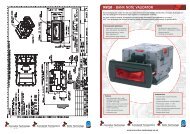
Technical Manual <strong>Evolution</strong> <strong>Hopper</strong> Standard Interface Model (EV1000)<br />
5. Mechanical Description<br />
5.1 General<br />
The hopper is mounted in a machine via the base plate.<br />
Electrical connection to the hopper is made via the 12 pin socket on the base plate which mates<br />
with the corresponding plug on the hopper body. Coins are stored in the cashbox section of the<br />
hopper and fed onto the elevator belt via a passage in the centre plate. The cutout in the centre plate<br />
has been designed to regulate the flow of coins onto the belt. The stirrer agitates the coins in the coin<br />
box in order to minimise the occurrence of bridging. The elevator belt is driven by a motor, gearbox,<br />
and idler gear. Coins are picked up at the bottom of the belt and carried up to the exit window. Optical<br />
sensors in the exit window detect the coins as they roll out of the hopper.<br />
A cable connects the main control board to the 12 way socket and carries all power supplies and<br />
control signals.<br />
5.2 Removal of the Electronics and Opto Sensor Board.<br />
All the electronics and sensors are placed on one board located behind the exit door at the side of the<br />
hopper. Slide the yellow button to the opposite position and remove the exit door were the electronics<br />
are mounted to. Take out the board for cleaning the optic sensors is a matter of seconds.<br />
Warning: be carefull by re-inserting the board back in the hopper not to damage the cable located at<br />
the back of the board!<br />
5.3 Track guard Removal and Refitting<br />
Firstly, locate cut away slots in Centre plate and End plate at the base of the track guard<br />
opposite the PCB. Push track guard up to reveal a gap between body moulding and the guard.<br />
Insert broad flat bladed screwdriver or equivalent into gap and gently lever out the guard until the<br />
leading edge is above the outside edge of the body mouldings. Now slide the guard down<br />
towards the cut out and gradually withdraw it. Slide back the track guard to refit.<br />
5.4 Coin Box Removal and Refitting<br />
5.5 Track and 12Pin Plug access<br />
Page 10 of 19 07-09-05