Evolution Hopper / 1780kB - KapiLajos.hu
Evolution Hopper / 1780kB - KapiLajos.hu
Evolution Hopper / 1780kB - KapiLajos.hu
You also want an ePaper? Increase the reach of your titles
YUMPU automatically turns print PDFs into web optimized ePapers that Google loves.
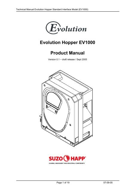
Technical Manual <strong>Evolution</strong> <strong>Hopper</strong> Standard Interface Model (EV1000)<br />
<strong>Evolution</strong> <strong>Hopper</strong> EV1000<br />
Product Manual<br />
Version 0.1 – draft release / Sept 2005<br />
Page 1 of 19 07-09-05
Technical Manual <strong>Evolution</strong> <strong>Hopper</strong> Standard Interface Model (EV1000)<br />
Revision History<br />
Revision Date Comment By<br />
0.1 5 sept 2005 Initial Release R.T.<br />
Page 2 of 19 07-09-05
Technical Manual <strong>Evolution</strong> <strong>Hopper</strong> Standard Interface Model (EV1000)<br />
This manual is intended only to assist the reader in the use of this product and therefore Suzo<br />
International shall not be held liable for any loss or damage whatsoever arising from the use of any<br />
information or particulars in, or any omission from this manual or any incorrect use of the product.<br />
Design and specifications are subject to change without notice.<br />
Wijzigingen in ontwerp en technische gegevens voorbehouden, zonder kennisgeving.<br />
La conception et les spécifications sont modifiables sans préavis.<br />
El diseño y especificaciones están sujetos a cambios sin previo aviso.<br />
WARNING!<br />
Failure to observe the interface requirements specified in this technical manual may<br />
result in miscounts, damage to the electronics and the motor of the hopper or create<br />
unacceptable voltage drops, affecting other units depending on the same power<br />
supply.<br />
Page 3 of 19 07-09-05
Technical Manual <strong>Evolution</strong> <strong>Hopper</strong> Standard Interface Model (EV1000)<br />
Contents<br />
1. Introduction .......................................................................................................................................... 6<br />
2. Safety Note .......................................................................................................................................... 6<br />
3. General Description ............................................................................................................................. 6<br />
3.1 Description ..................................................................................................................................... 6<br />
3.2 Options ........................................................................................................................................... 7<br />
3.2.1 Track options ........................................................................................................................... 7<br />
3.2.2 Connector position................................................................................................................... 7<br />
3.2 Level Sensing................................................................................................................................. 7<br />
3.3 Connectors ..................................................................................................................................... 7<br />
3.4 Coin Sizes ...................................................................................................................................... 8<br />
3.5 Baseplate ....................................................................................................................................... 8<br />
4. Installation............................................................................................................................................ 9<br />
4.1 Baseplate ....................................................................................................................................... 9<br />
4.2 Safety ............................................................................................................................................. 9<br />
5. Mechanical Description...................................................................................................................... 10<br />
5.1 General......................................................................................................................................... 10<br />
5.2 Removal of the Electronics and Opto Sensor Board. .................................................................. 10<br />
5.3 Track guard Removal and Refitting.............................................................................................. 10<br />
5.4 Coin Box Removal and Refitting .................................................................................................. 10<br />
5.5 Track and 12Pin Plug access....................................................................................................... 10<br />
6. Electronic Description ........................................................................................................................ 11<br />
6.1 General Electronic Description..................................................................................................... 11<br />
6.2 Operating Mode Selection............................................................................................................ 11<br />
6.2.1 MODE 0 DIRECT SWITCHING............................................................................................. 11<br />
6.2.2 MODE 1 LOGIC CONTROL .................................................................................................. 11<br />
6.2.3 MODE 2 COIN COUNTING................................................................................................... 11<br />
6.2.4 RESET FUNCTION ............................................................................................................... 12<br />
6.3 Optical Sensors ............................................................................................................................ 12<br />
6.4 Optical Security Feature............................................................................................................... 12<br />
6.5 Motor Operation ........................................................................................................................... 12<br />
6.6 Motor Current Limit....................................................................................................................... 13<br />
6.7 Coins With Holes.......................................................................................................................... 13<br />
6.8 High Security Exit Window ........................................................................................................... 13<br />
6.8.1 Description............................................................................................................................. 13<br />
6.8.2 Security.................................................................................................................................. 13<br />
6.8.3 Opto test ................................................................................................................................ 13<br />
9. Electrical Specification Power Supply Requirements ........................................................................ 14<br />
9.1 Power Supply ............................................................................................................................... 14<br />
9.1.1 Suggested connection ........................................................................................................... 14<br />
10. Technical Specifications .................................................................................................................. 15<br />
10.1 Coin Sizes .................................................................................................................................. 15<br />
10.2 Capacity...................................................................................................................................... 15<br />
10.3 Connector................................................................................................................................... 15<br />
10.4 Electrical Interface...................................................................................................................... 15<br />
10.5 Logic Inputs ................................................................................................................................ 16<br />
10.6 Logic Outputs ............................................................................................................................. 16<br />
10.7 Interface Options ........................................................................................................................ 16<br />
10.8 Payout Rate................................................................................................................................ 16<br />
10.9 EMC approval............................................................................................................................. 16<br />
10.10 Environment ............................................................................................................................. 16<br />
11. Dimensions ...................................................................................................................................... 17<br />
12. Exploded View ................................................................................................................................. 19<br />
Page 4 of 19 07-09-05
Technical Manual <strong>Evolution</strong> <strong>Hopper</strong> Standard Interface Model (EV1000)<br />
Tables<br />
Table 1: <strong>Hopper</strong> capacity for some popular coins ................................................................................... 6<br />
Table 2: Coin size vs Track type.............................................................................................................. 8<br />
Table 3: Mode selection input logic ....................................................................................................... 11<br />
Table 4: Coin size vs Track type............................................................................................................ 15<br />
Table 5: Electrical Interface ................................................................................................................... 15<br />
Figures<br />
Figure 1: Connector locations.................................................................................................................. 7<br />
Figure 2: Connector pinout ...................................................................................................................... 7<br />
Figure 3: Base plate................................................................................................................................. 9<br />
Figure 4: Connector pinout .................................................................................................................... 15<br />
Figure 5: Logic inputs............................................................................................................................. 16<br />
Figure 6: Logic outputs .......................................................................................................................... 16<br />
Figure 7: <strong>Hopper</strong> dimensions................................................................................................................. 17<br />
Figure 8: Base plate dimensions ........................................................................................................... 18<br />
Page 5 of 19 07-09-05
Technical Manual <strong>Evolution</strong> <strong>Hopper</strong> Standard Interface Model (EV1000)<br />
1. Introduction<br />
The Suzo-Happ group has now introduced it’s own version of a belt driven hopper.<br />
After the succesfull Cube hopper, the Gold series, the Excel Casino <strong>Hopper</strong>s and the Escendo<br />
escalator hopper has Suzo-Happ made it’s own improved version of this unique hopper concept.<br />
Easier service-ability and higher speed are the two key elements for developing this product.<br />
This product is compatible with most other belt driven hoppers in the market.<br />
2. Safety Note<br />
To meet the requirements for EN 60950 the equipment must be installed according to the<br />
following requirements:The equipment must be protected by a 3A fuse.<br />
The equipment must be supplied from a SELV limited power source.<br />
The equipment must be installed in an enclosure but positioned so that it is external<br />
to any fire enclosure area within the main enclosure.<br />
3. General Description<br />
3.1 Description<br />
The <strong>Evolution</strong> <strong>Hopper</strong> is an universal intelligent large capacity coin and token dispenser ideal for a<br />
wide range of applications including Gaming, Vending and Transportation systems.<br />
The <strong>Evolution</strong> hopper will handle most coins in the range 16.25mm to 30mm diameter and 1.25mm-<br />
3.5mm thick, giving the following approximate capacities:<br />
Capacity = <strong>Hopper</strong> volume / Coin volume =<br />
1,200,000<br />
π x D 2<br />
x T<br />
4<br />
D = Coin diameter (mm)<br />
T = Coin thickness (mm)<br />
Diameter (mm) Thickness (mm) Coin type Approx. capacity<br />
25.75 2.20 2 Euro 1000<br />
23.25 2.35 1 Euro 1200<br />
24.25 2.40 0.50 Euro 1100<br />
24.25 1.75 US quarter 1500<br />
Table 1: <strong>Hopper</strong> capacity for some popular coins<br />
The <strong>Evolution</strong> hopper standard can handle coins between 21.01 and 30.00 mm.<br />
A Euro coin track is available for all euro coins (between 19.00 – 26.40 mm).<br />
A small coin track is available for smaller coins between 16.25 and 20.90 mm (optional).<br />
A large coin track is in preparation for coins of 31 mm (optional).<br />
The payout speed depends on the coin size and the amount of coins in the hopper but the average<br />
speed is approximately 4 coins per second.<br />
Precise payout is ensured through optical sensing and verifying of coin dispensing with an<br />
electronic security signal which alerts against coin jams, failed sensors and a bad power supply.<br />
LED indicators are provided for easy visual checking of power supply, security status and coin<br />
sensors.<br />
The standard interface can be set in 3 different modes:<br />
Mode0: <strong>Hopper</strong> starts paying out as soon as the power is supplied<br />
Mode1: <strong>Hopper</strong> is started by a logic control line (active low).<br />
Mode2: <strong>Hopper</strong> pays a coin for each start pulse it receives.<br />
Page 6 of 19 07-09-05
Technical Manual <strong>Evolution</strong> <strong>Hopper</strong> Standard Interface Model (EV1000)<br />
3.2 Options<br />
3.2.1 Track options<br />
The standard <strong>Evolution</strong> <strong>Hopper</strong> handles coins in the diameter range of 21.01 – 30.00 mm,<br />
A Euro coin track is available for all euro coins (between 19.00 – 26.40 mm).<br />
The small coin <strong>Evolution</strong> <strong>Hopper</strong> handles coins in the diameter range of 16.25 mm 20.90 mm.<br />
3.2.2 Connector position<br />
The 12pin connector can be in one of two positions, either on the opposite side of the coin exit,<br />
known as the Rear (R) position, or on the same side as the coin exit, known as the Front (F) position.<br />
Standard the <strong>Evolution</strong> hopper is supplied with the connector on the adjacent position.<br />
The user can easily change this on a <strong>Evolution</strong> hopper by loosen two screws on the botton section<br />
and take out this part than place the cable with the connector at the opposite side.<br />
Connector can be located<br />
at the Rear or Front<br />
positions<br />
Figure 1: Connector locations<br />
3.2 Level Sensing<br />
All <strong>Evolution</strong> <strong>Hopper</strong>s are standard supplied with a low level and high level sensing function.<br />
3.3 Connectors<br />
<strong>Evolution</strong> <strong>Hopper</strong> is only available with the Industry compatible connector.<br />
(compatible with the green CINCH connector)<br />
Figure 2: Connector pinout<br />
Pin<br />
Description<br />
1 Motor supply 0 Vdc<br />
2 Logic supply 0 Vdc<br />
3 Coin Exit output<br />
4 IN1<br />
5 Security output<br />
6 High or Top level sense output<br />
7 Low level sense output<br />
8 IN2<br />
9 Motor supply 24Vdc<br />
10 Logic supply 12 - 24Vdc<br />
11 Coin Exit output<br />
12 IN3<br />
Page 7 of 19 07-09-05
Technical Manual <strong>Evolution</strong> <strong>Hopper</strong> Standard Interface Model (EV1000)<br />
3.4 Coin Sizes<br />
Track type Coin sizes Art. nr.<br />
Standard<br />
(€2, €1, €0.50, €0.20)<br />
Euro<br />
(€2, €1, €0.50, €0.20, €0.10, €0.05)<br />
Euro small<br />
(€0.10, €0.05, €0.02, €0.01)<br />
Table 2: Coin size vs Track type<br />
21.01 – 30.00 mm x 1.25 – 3.30 mm<br />
19.00 – 26.40 mm x 1.50 – 2.50 mm<br />
16.25 – 20.90 mm x 1.00 – 3.10 mm<br />
3.5 Baseplate<br />
The baseplate offers easy slide in and out function with a pre-fitted connector that can easily be<br />
removed for fitting it in a cable-harness.<br />
The baseplate is standard suppied with the <strong>Evolution</strong> hopper.<br />
See Figure 3: Base plate.<br />
Page 8 of 19 07-09-05
Technical Manual <strong>Evolution</strong> <strong>Hopper</strong> Standard Interface Model (EV1000)<br />
4. Installation<br />
Important: S<strong>hu</strong>t-off the power from the host machine until any installation work is completed.<br />
4.1 Baseplate<br />
1. Secure the baseplate in position, using the six fixing holes. The hole positions are shown in<br />
Figure 3: Base plate.<br />
2. Wire up the baseplate connector to the host machine see<br />
Pin<br />
Description<br />
1 Motor supply 0 Vdc<br />
2 Logic supply 0 Vdc<br />
3 Coin Exit output<br />
4 IN1<br />
5 Security output<br />
6 High or Top level sense output<br />
7 Low level sense output<br />
8 IN2<br />
9 Motor supply 24Vdc<br />
10 Logic supply 12 - 24Vdc<br />
11 Coin Exit output<br />
12 IN3<br />
Figure 2: Connector pinout for connector details, and sections xx for interfacing recommendations.<br />
NOTE: The wire to be used should have a maximum length of 3 metres, and must be capable of<br />
handling the maximum currents and voltages specified in Table 5: Electrical Interface.<br />
3. Slide the hopper into the baseplate and ensure that the two halves of the connector are<br />
securely mated.<br />
4. Turn on the power.<br />
4.2 Safety<br />
1. Do not put a hand into the hopper while the motor is running.<br />
2. Static. It is possible for coins paid out to have a static charge on them.<br />
3. Coins should be discharged to earth before being presented to the user.<br />
Figure 3: Base plate<br />
Page 9 of 19 07-09-05
Technical Manual <strong>Evolution</strong> <strong>Hopper</strong> Standard Interface Model (EV1000)<br />
5. Mechanical Description<br />
5.1 General<br />
The hopper is mounted in a machine via the base plate.<br />
Electrical connection to the hopper is made via the 12 pin socket on the base plate which mates<br />
with the corresponding plug on the hopper body. Coins are stored in the cashbox section of the<br />
hopper and fed onto the elevator belt via a passage in the centre plate. The cutout in the centre plate<br />
has been designed to regulate the flow of coins onto the belt. The stirrer agitates the coins in the coin<br />
box in order to minimise the occurrence of bridging. The elevator belt is driven by a motor, gearbox,<br />
and idler gear. Coins are picked up at the bottom of the belt and carried up to the exit window. Optical<br />
sensors in the exit window detect the coins as they roll out of the hopper.<br />
A cable connects the main control board to the 12 way socket and carries all power supplies and<br />
control signals.<br />
5.2 Removal of the Electronics and Opto Sensor Board.<br />
All the electronics and sensors are placed on one board located behind the exit door at the side of the<br />
hopper. Slide the yellow button to the opposite position and remove the exit door were the electronics<br />
are mounted to. Take out the board for cleaning the optic sensors is a matter of seconds.<br />
Warning: be carefull by re-inserting the board back in the hopper not to damage the cable located at<br />
the back of the board!<br />
5.3 Track guard Removal and Refitting<br />
Firstly, locate cut away slots in Centre plate and End plate at the base of the track guard<br />
opposite the PCB. Push track guard up to reveal a gap between body moulding and the guard.<br />
Insert broad flat bladed screwdriver or equivalent into gap and gently lever out the guard until the<br />
leading edge is above the outside edge of the body mouldings. Now slide the guard down<br />
towards the cut out and gradually withdraw it. Slide back the track guard to refit.<br />
5.4 Coin Box Removal and Refitting<br />
5.5 Track and 12Pin Plug access<br />
Page 10 of 19 07-09-05
Technical Manual <strong>Evolution</strong> <strong>Hopper</strong> Standard Interface Model (EV1000)<br />
6. Electronic Description<br />
6.1 General Electronic Description<br />
Operation of the hopper is controlled by a 8-bit microprocessor.<br />
The firmware allows the choice of 3 different operating modes.<br />
It also provides PWM motor control drive via a MOSFET bridge and an optical payout detection output.<br />
Separate power supplies are recommended for the motor supply input and the logic supply input.<br />
6.2 Operating Mode Selection<br />
Three modes of operation are available, selected via inputs IN1 and IN2 (pins 4 and 8 of the 12<br />
way connector). Input signals may be controlled by the host machine, or may be hardwired.<br />
Additionally, input IN3 (pin 12) is the logic control line, used in modes 1 and 2. These inputs are<br />
passive pullup and active pulldown.<br />
The signals therefore default to logic '1 if left open circuit.<br />
NOTE: It is strongly recommended that if these inputs are to be controlled by the host machine,<br />
then open collector NPN transistors, referenced to logic OV (connector pin 2) be used to set the<br />
input levels to IN1, IN2 and IN3.<br />
With the exception of RESET mode which can be applied at any time (with instantaneous effect),<br />
Mode selection is determined at powerup.<br />
The hopper allows a 100ms timeout after powerup, then reads the inputs IN1 and IN2. The hopper will<br />
remain in the selected mode until the power is removed, i.e., any further changes in the levels at IN1<br />
and IN2 will be ignored. See Table 3: Mode selection input logic.<br />
Mode IN1 IN2<br />
0 1 1<br />
1 0 0<br />
2 1 0<br />
Reset 0 1<br />
Table 3: Mode selection input logic<br />
6.2.1 MODE 0 DIRECT SWITCHING<br />
This is the default operating Mode, and is selected when all of the input selectors are left<br />
open circuit. When the 24V line is established, the motor starts in the forward direction and<br />
when the 24V power line is removed, the motor is braked.<br />
6.2.2 MODE 1 LOGIC CONTROL<br />
In this mode the logic and 24V power supplies can be permanently connected and motor<br />
function is determined via a logic level on the IN3 input.<br />
When IN1 (pin 4) and IN2 (pin 8) are pulled down to OV at power up, mode 1 is selected.<br />
The operation of the motor is now controlled via a logic signal on IN3 (pin 12). With the 24V<br />
supply present, a low level on IN3 starts the motor and a high level on IN3 brakes the motor.<br />
6.2.3 MODE 2 COIN COUNTING<br />
In this mode, the hopper will pay out a coin for every pulse it receives on input IN3.<br />
Mode 2 is selected by setting IN1 (pin 4) high and IN2 (pin 8) low at power up. Once<br />
selected, the processor continually scans input IN3. When a pulse is detected on IN3, an<br />
internal register is incremented. When a coin is paid out, it is detected and the register is<br />
decremented.<br />
The motor is started when the internal coin register is nonzero and is stopped when it<br />
returns to zero. The maximum count for the coin register is 4095 coins. Should the 24V line<br />
fail at any point, the motor is braked. When the 24V line reappears,<br />
the payout of coins continues until the coin register returns to zero. Coin counting on IN3 can take<br />
place while coins are being paid out. A pulse is defined as a falling edge followed by a rising edge.<br />
Pulse edges may be no closer than 5ms. This is so that the processor has adequate time to poll the<br />
IN3 pin and debounce. This represents a maximum pulse rate of 100Hz.<br />
Page 11 of 19 07-09-05
Technical Manual <strong>Evolution</strong> <strong>Hopper</strong> Standard Interface Model (EV1000)<br />
There is no lower limit. The waveform duty cycle is unimportant.<br />
At powerup in mode 2, IN3 is high. The first falling edge will be recognised as the first pulse<br />
and the hopper motor will start running.<br />
Pulsing on IN3 should not commence earlier than 130ms after the logic supply has been<br />
established. This will allow for the powerup timeout of 100ms and further processing time<br />
prior to running the main program.<br />
6.2.4 RESET FUNCTION<br />
In this mode the <strong>Hopper</strong> is reset, i.e. processor reset and motor drive disabled. This function is<br />
provided as added security enabling the host machine to immediately stop the <strong>Hopper</strong> irrespective of<br />
its mode of operation.<br />
Whilst in this mode connecting IN3 (pin 12) to ground turns the exit window sensor off in<br />
order to test it is operative. Confirmation would be given as a signal output on pin 3 and 11 of<br />
the 12 pin connector.<br />
6.3 Optical Sensors<br />
Optical sensors are fitted on the optic board in the exit window to detect coin payout.<br />
A debounced coin output is available on pin 3 and pin 11. When no coins are present at the exit<br />
window, the optical sensors are clear, the output transistors are open circuit, and the LED indicator is<br />
off. Coins passing the optical sensors obstruct the light path causing the output transistors to pull down<br />
to OV and the GREEN LED SENSOR indicator switches on.<br />
6.4 Optical Security Feature<br />
The output of the optical sensor is monitored by the microprocessor and if the sensor remains<br />
obstructed for more than one second, the motor will be braked and will remain off until either the<br />
sensor is cleared or power down takes place. This action will result if a coin jams in the exit<br />
window or if the optical sensor fails which could be checked by toggling IN3 in Reset mode.<br />
If the security feature should operate, the security output on output pin 5 and the LED SECURITY<br />
indicator will be switched off.<br />
The optical security feature operates identically in all 3 Modes.<br />
6.5 Motor Operation<br />
The DC motor is controlled by the processor via a transistor bridge. The motor will run provided<br />
that one of the sets of conditions shown below is met. If any single condition fails then the motor<br />
is braked and remains so until all conditions bee true, or a power down occurs.<br />
Mode 0 Motor Start Conditions:<br />
- Security feature true<br />
- 24V line true.<br />
Mode 1 Motor Start Conditions:<br />
- Security feature true<br />
- 24V line true<br />
- IN3 input low.<br />
Mode 2 Motor Start Conditions:<br />
- Security line true<br />
- 24V line true<br />
- internal coin count nonzero.<br />
When braking is initiated and for whatever reason, 50ms braking is carried out even if the fault<br />
condition recovers before that time. This guarantees that the motor is stationary when the<br />
bridge drivers change state, so that no excess current flows in the motor windings.<br />
Page 12 of 19 07-09-05
Technical Manual <strong>Evolution</strong> <strong>Hopper</strong> Standard Interface Model (EV1000)<br />
6.6 Motor Current Limit<br />
The motor current is monitored by the processor. When the motor initially starts, the current is build up<br />
gradually using PWM-current control. This reduces the high initial surge currents that occur in noncurrent<br />
controlled motor driver circuits.<br />
If the current rises above a preset value, then a jam is deemed to have occurred. The motor is braked<br />
for 50ms then reversed for 150ms. After a further 50ms braking, the motor is started in the forward<br />
direction again.<br />
The current is tested after 100ms and if the jam has not been cleared the reversing cycle will be<br />
repeated. This action will continue until the jam has cleared. This reversing action is effective in<br />
clearing soft jams.<br />
One further action is to test the current in the reverse direction during the final 50ms of the<br />
reversing cycle. If during that time period an over current is detected, then the motor will be<br />
braked for 50ms and then disabled for 1 second. This action limits the duty cycle sufficiently in<br />
the case where a jam is solid in order to prevent motor damage.<br />
6.7 Coins With Holes<br />
The <strong>Evolution</strong> hopper will work with most coins/tokens with holes depending on the size of the hole in<br />
relation to the diameter. To make sure whether your desired coin is qualified within the specifications<br />
of the <strong>Evolution</strong> <strong>Hopper</strong> please contact the Suzo-Happ technical department<br />
The exit window has been designed so that more coins with holes will be counted correctly.<br />
No adjustments are necessary to cope with standard and small coins.<br />
6.8 High Security Exit Window<br />
6.8.1 Description<br />
The payout window uses optics consisting of an IR-Led transmitting a beam that is reflected by a<br />
prism in an U-shaped form and received back on an IR-receiver.<br />
The intensity of the IR-pulse is minimized, so that the (somewhat transparant) plastic coins as well as<br />
highly reflective coins are detected as optimal as possible.<br />
The intensity of the IR-pulse is adjusted dynamically to a higher level if the opto-sensor becomes dirty.<br />
6.8.2 Security<br />
- The IR-led transmits pulses with a random duty-cycle between 16 – 20%.<br />
- When light is received when no IR-pulse is being transmitted, (exit window is 'blinded' by external<br />
light), the hopper will stop immediately if it was running, the security led will go off and the security<br />
output will go high (error state).<br />
- If the opto-sensor is interrupted for more than 1 second, the hopper will also stop and go into error<br />
state. If the coin exit becomes unblocked again and the hopper start conditions are still met, the<br />
hopper will resume running.<br />
6.8.3 Opto test<br />
By holding the hopper in reset and toggling the IN3 line, the optics can be checked for a<br />
blockage prior to paying out.<br />
During Reset, a High on IN3 will cause a low on "Output 1" and "Output 2". Alternately a Low<br />
on IN3 will cause a high on "Output 1" and "Output 2".<br />
NOTE:This is only true if the optics are NOT blocked.<br />
Page 13 of 19 07-09-05
Technical Manual <strong>Evolution</strong> <strong>Hopper</strong> Standard Interface Model (EV1000)<br />
9. Electrical Specification Power Supply Requirements<br />
9.1 Power Supply<br />
For ease of use and maximum noise suppression, the 0 volt logic line (pin 2) and the motor 0<br />
volt line (pin 1) are not moned inside the hopper. This means the outputs from the hopper<br />
(Opto and Security) are noise free.<br />
9.1.1 Suggested connection<br />
T.b.d.<br />
Page 14 of 19 07-09-05
Technical Manual <strong>Evolution</strong> <strong>Hopper</strong> Standard Interface Model (EV1000)<br />
10. Technical Specifications<br />
10.1 Coin Sizes<br />
Track type Coin sizes Art. nr.<br />
Standard<br />
(€2, €1, €0.50, €0.20)<br />
Euro<br />
(€2, €1, €0.50, €0.20, €0.10, €0.05)<br />
Euro small<br />
(€0.10, €0.05, €0.02, €0.01)<br />
Table 4: Coin size vs Track type<br />
21.01 – 30.00 mm x 1.25 – 3.30 mm<br />
19.00 – 26.40 mm x 1.50 – 2.50 mm<br />
16.25 – 20.90 mm x 1.00 – 3.10 mm<br />
10.2 Capacity<br />
Capacity = <strong>Hopper</strong> volume / Coin volume =<br />
10.3 Connector<br />
1,200,000<br />
π x D 2<br />
x T<br />
4<br />
D = Coin diameter (mm)<br />
T = Coin thickness (mm)<br />
Pin<br />
Description<br />
1 Motor supply 0 Vdc<br />
2 Logic supply 0 Vdc<br />
3 Coin Exit output<br />
4 IN1<br />
5 Security output<br />
6 High or Top level sense output<br />
7 Low level sense output<br />
8 IN2<br />
9 Motor supply 24Vdc<br />
10 Logic supply 12 - 24Vdc<br />
11 Coin Exit output<br />
12 IN3<br />
Figure 4: Connector pinout<br />
10.4 Electrical Interface<br />
Electrical Interface Parallel Serial<br />
Voltage: nominal 24 VDC 24 VDC<br />
minimum 18 VDC 20 VDC<br />
maximum 26 VDC 26 VDC<br />
Current (typical):<br />
idle 40 mA 40 mA<br />
empty 0.2 A 0.2 A<br />
full 0.7 A 0.7 A<br />
surge 2.5 A 2.5 A<br />
Table 5: Electrical Interface<br />
Page 15 of 19 07-09-05
Technical Manual <strong>Evolution</strong> <strong>Hopper</strong> Standard Interface Model (EV1000)<br />
10.5 Logic Inputs<br />
Description<br />
Value (Vin)<br />
Absolute max logic 0 input = 2.6V<br />
Figure 5: Logic inputs<br />
10.6 Logic Outputs<br />
Description<br />
Output level 0<br />
Max sink current<br />
Max pullup voltage<br />
Coin exit typical pulse width<br />
Figure 6: Logic outputs<br />
Value<br />
Technical Manual <strong>Evolution</strong> <strong>Hopper</strong> Standard Interface Model (EV1000)<br />
11. Dimensions<br />
Figure 7: <strong>Hopper</strong> dimensions<br />
Page 17 of 19 07-09-05
Technical Manual <strong>Evolution</strong> <strong>Hopper</strong> Standard Interface Model (EV1000)<br />
Figure 8: Base plate dimensions<br />
Page 18 of 19 07-09-05
Technical Manual <strong>Evolution</strong> <strong>Hopper</strong> Standard Interface Model (EV1000)<br />
12. Exploded View<br />
Figure 9: Exploded view<br />
Page 19 of 19 07-09-05


