Mid-term 2.pdf - UBC Mechanical Engineering
Mid-term 2.pdf - UBC Mechanical Engineering
Mid-term 2.pdf - UBC Mechanical Engineering

Create successful ePaper yourself
Turn your PDF publications into a flip-book with our unique Google optimized e-Paper software.
MECH 260 Mechanics of Materials<br />
<strong>Mid</strong>-<strong>term</strong> Examination 2<br />
Duration: 50 minutes<br />
Important Note: Closed-book/notes; One 8 1 2′′<br />
× 11<br />
′′<br />
(2-sided) student-prepared fact<br />
sheet is allowed; calculator (Only the arithmetic mode, if it is a programmable calculator)<br />
is allowed.<br />
Question 1<br />
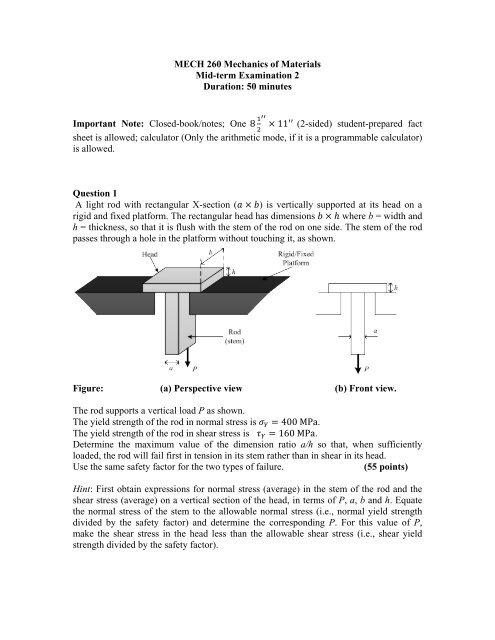
A light rod with rectangular X-section (a × b) is vertically supported at its head on a<br />
rigid and fixed platform. The rectangular head has dimensions b × h where b = width and<br />
h = thickness, so that it is flush with the stem of the rod on one side. The stem of the rod<br />
passes through a hole in the platform without touching it, as shown.<br />
Figure: (a) Perspective view (b) Front view.<br />
The rod supports a vertical load P as shown.<br />
The yield strength of the rod in normal stress is σ Y = 400 MPa.<br />
The yield strength of the rod in shear stress is τ Y = 160 MPa.<br />
De<strong>term</strong>ine the maximum value of the dimension ratio a/h so that, when sufficiently<br />
loaded, the rod will fail first in tension in its stem rather than in shear in its head.<br />
Use the same safety factor for the two types of failure.<br />
(55 points)<br />
Hint: First obtain expressions for normal stress (average) in the stem of the rod and the<br />
shear stress (average) on a vertical section of the head, in <strong>term</strong>s of P, a, b and h. Equate<br />
the normal stress of the stem to the allowable normal stress (i.e., normal yield strength<br />
divided by the safety factor) and de<strong>term</strong>ine the corresponding P. For this value of P,<br />
make the shear stress in the head less than the allowable shear stress (i.e., shear yield<br />
strength divided by the safety factor).
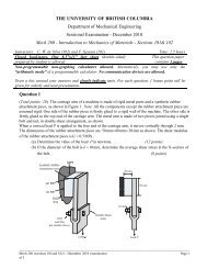
Question 2<br />
A schematic diagram of the anchoring cable (steel) of a rigid/fixed sail post at Canada<br />
Place in Vancouver is shown. The cable is firmly attached to the top of the sail post at<br />
one end. The other end of the cable has a rigid end cap, the position of which may be<br />
adjusted by means of a tensioning device. The tensioning device has an identical pair of<br />
steel bolts with nuts, and is rigidly attached to a fixed support base. The bolts pass<br />
through the two holes in the end cap of the cable. The tensioning is done by tightening<br />
the two bolts by equal amounts.<br />
Under unstrained conditions:<br />
L = length of the cable<br />
L/10 = length of each bolt (from the nut position to the head).<br />
Also,<br />
δ = screw pitch of a bolt/nut<br />
E = Young’s modulus of cable = Young’s modulus of bolt.<br />
Assume that the area of X-section of the cable = area of X-section of the bolt.<br />
If both nuts are tightened through n turns each, in the same direction, de<strong>term</strong>ine an<br />
expression for the:<br />
(a) Tensile stress in the cable<br />
(30 points)<br />
(b) Tensile stress in each bolt<br />
(15 points)<br />
in <strong>term</strong>s of E, L, n and δ.<br />
Figure: Sail-post anchoring cable system.<br />
2