Technical Installation and Operation Manual - Sonder
Technical Installation and Operation Manual - Sonder
Technical Installation and Operation Manual - Sonder

Create successful ePaper yourself
Turn your PDF publications into a flip-book with our unique Google optimized e-Paper software.
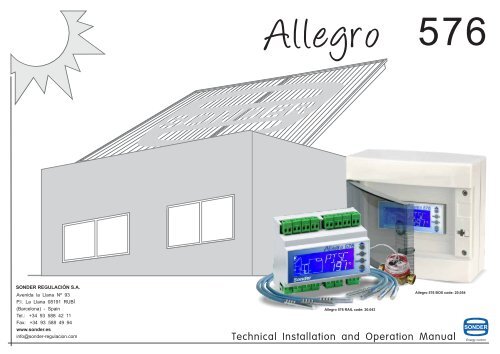
Allegro 576<br />
SONDER REGULACIÓN S.A.<br />
Avenida la Llana Nº 93<br />
P.I. La Llana 08191 RUBÍ<br />
(Barcelona) - Spain<br />
Tel.: +34 93 588 42 11<br />
Fax: +34 93 588 49 94<br />
www.sonder.es<br />
info@sonder-regulacion.com<br />
Allegro 576 BOX code: 20.054<br />
Allegro 576 RAIL code: 20.043<br />
<strong>Technical</strong> <strong>Installation</strong> <strong>and</strong> <strong>Operation</strong> <strong>Manual</strong><br />
Energy control
NOTES<br />
5815VØ MAY-09<br />
2 35
NOTES<br />
CONTENTS<br />
Warnings<br />
4<br />
Presentation<br />
5<br />
<strong>Installation</strong> <strong>and</strong> connection<br />
6<br />
Description ...................................................................................6<br />
<strong>Technical</strong> specifications ..............................................................6<br />
Dimensions ................................................................................6<br />
Connections ................................................................................7<br />
<strong>Operation</strong><br />
8<br />
Getting started ............................................................................8<br />
Probe <strong>and</strong> relay test ...................................................................9<br />
Screen view .............................................................................10<br />
Configuration ..............................................................................11<br />
Factory settings <strong>and</strong> resetting ..................................................12<br />
Resource control .......................................................................13<br />
Menu<br />
16<br />
Statistics .....................................................................................16<br />
Functions .....................................................................................18<br />
Systems<br />
Settings<br />
.....................................................................................22<br />
.....................................................................................26<br />
34<br />
33
WARNINGS<br />
SAFETY INSTRUCTIONS<br />
- Before installing the Allegro 576 regulator, ensure<br />
that the environmental conditions (operating<br />
temperature, humidity, pollution <strong>and</strong> gas emissions)<br />
are suitable, as any of these factors can cause the<br />
unit to malfunction.<br />
- When h<strong>and</strong>ling the Allegro 576 regulator, whether<br />
for installation or repairs, disconnect it from the<br />
electricity mains.<br />
- The Allegro 576 is an independent control device for<br />
surface assembly with wiring through tubes for<br />
correct installation.<br />
- Electrical connections other than those indicated in<br />
this manual <strong>and</strong> on the connection label on the side<br />
of the device are not permitted. The connections<br />
referred to in this manual are those of the regulator;<br />
to connect the rest of the components, please<br />
consult the corresponding instructions for each unit<br />
(collectors, tanks, valves, etc.). For correct<br />
operation of the installation, check that the technical<br />
needs of the elements are compatible.<br />
WARRANTY CONDITIONS<br />
This device has a two-year warranty. The warranty<br />
is limited to the replacement of faulty parts, which will<br />
be restored to the same condition in which they were<br />
received. No packaging, batteries, instructions or any<br />
other accessories included with the product will be<br />
replaced.<br />
We cannot accept any responsibility for devices<br />
damaged as a result of poor h<strong>and</strong>ling, omission of the<br />
warnings provided in this manual or technical<br />
ignorance with regard to the requirements of the<br />
installation.<br />
For repairs during the warranty period, customers<br />
are required to provide proof of purchase <strong>and</strong> an<br />
accurate description detailing the defect or the<br />
anomalous behaviour of the product according to the<br />
user.<br />
In the event of repairs outside the warranty, the user<br />
will be informed of their viability <strong>and</strong> cost.<br />
Assessments carried out by our technical department<br />
may incur an additional cost for the user.<br />
- This regulator is not a security device nor can it be<br />
used as one; it is the responsibility of the installer to<br />
provide the protection most suited to each type of<br />
installation (officially authorised).<br />
- The assembly, electrical connection, commissioning<br />
<strong>and</strong> maintenance procedures must be carried out by<br />
qualified personnel.<br />
- Should you encounter any defects that could cause<br />
damage or malfunctions, do not connect the device.<br />
- Should you have any doubts regarding the operation<br />
or correct installation of the device, do not connect it<br />
to the electricity mains <strong>and</strong> consult a professional<br />
technician.<br />
- <strong>Sonder</strong> Regulación S.A. reserves the right to modify<br />
the product, technical data <strong>and</strong> assembly <strong>and</strong> use<br />
instructions without prior notification.<br />
The following cases are excluded from the warranty:<br />
Devices whose serial number has been worn away,<br />
erased or modified.<br />
Devices which were not connected or used in<br />
accordance with the instructions enclosed with the<br />
device.<br />
Devices that have been modified without prior<br />
agreement with the manufacturer.<br />
Devices damaged due to knocks, spills or gas<br />
emissions.<br />
Devices with normal wear <strong>and</strong> tear or which are<br />
damaged from inappropriate use.<br />
Shipment <strong>and</strong> reception costs.<br />
Requests for compensation for loss of earnings,<br />
usage compensation <strong>and</strong> indirect damage, unless the<br />
company is deemed legally responsible.<br />
New product<br />
Moderato-SR<br />
Remote adjustment probe<br />
with range from 6 to 30 ºC<br />
Versions to order<br />
with probe<br />
PTC2000<br />
Probes<br />
- Radiation<br />
- Temperature<br />
4<br />
33
PRESENTATION<br />
Consult our wide<br />
range of products<br />
• 1 Allegro 576 solar regulator<br />
• 3 contact terminals for probes<br />
• 3 PT1000 1.5-metre probes<br />
• <strong>Technical</strong> manual<br />
• Quick start guide<br />
EQUIPMENT CONTAINED IN THE KIT<br />
RAIL<br />
BOX<br />
POSSIBLE ACCESSORIES<br />
Visit our WEBSITE<br />
L<strong>and</strong>line telephone control<br />
3 channels<br />
3 alarms<br />
L= 20mm<br />
L= 50mm<br />
Stainless-steel sheaths<br />
New products<br />
All our products<br />
<strong>Technical</strong> documentation<br />
Catalogues<br />
L= 100mm<br />
Telephone control - l<strong>and</strong>line / mobile<br />
1 channel<br />
1 alarm Water meter with pulse output<br />
GSM<br />
L= 200mm<br />
32<br />
www.sonder.es<br />
Consult us about models for remote<br />
management <strong>and</strong> data storage with SD card<br />
Conductive<br />
paste for sheaths<br />
5
DESCRIPTION<br />
First of all we would like to thank you for your purchase <strong>and</strong> we hope that the Allegro 576 meets the needs of<br />
your installation.<br />
The Allegro 576 is a thermal solar energy regulator with six 5A 250V~ relay outputs <strong>and</strong> seven PT1000 probe<br />
inputs (three 1.5 metre probes are included, each with a range of -50 ºC to +200 ºC), in addition to a pulse input.<br />
The relays are potential-free contacts, which means that they only act as switches <strong>and</strong> the devices connected to<br />
the relay need to be powered.<br />
When programming the Allegro 576 you will find different predefined installation systems that will help you to<br />
quickly <strong>and</strong> easily configure your installation. Depending on the system you have chosen, you may activate<br />
additional functions, such as unit heater, independent thermostat, return increase, double pump, anti-frost,<br />
calorimeter <strong>and</strong> tubular sensors, provided that the resources (relays) required for the functions are not being<br />
used by the system chosen to configure your installation.<br />
TECHNICAL SPECIFICATIONS<br />
DIMENSIONS<br />
Assembly on DIN rail<br />
6<br />
90<br />
INSTALLATION AND CONNECTION<br />
Input power<br />
Outputs<br />
Inputs<br />
Wiring<br />
Environment<br />
<strong>Operation</strong><br />
Tests<br />
R 1<br />
230 Vac +10% -15% 50/60 Hz max. 2 VA.<br />
6 SPDT relays max. 250 V~, 5 A. Potential-free contacts (acting as switches).<br />
7 PT1000 probes / Range: -50 ºC to +200 ºC + 1 calorimeter (pulses).<br />
ºC -40 -20 0 +20 +40 +60 +80 +100 +120 +140 +160 +180 +200<br />
W 843 922 1000 1078 1155 1232 1309 1385 1461 1536 1611 1685 1758<br />
Min. power section = 0.75 mm² / Min. relay section = 1.5 mm² / Max. section = 2.5 mm² / Type = H05v-k.<br />
Temperature = 0º C to 40 ºC / Humidity = 20% to 85% / Pollution = 2.<br />
Software class A; Action type 1.B.<br />
Assigned pulse voltage: 2500 V.<br />
Temperatures for high-pressure ball valve: 100ºC (parts supporting voltage conductors).<br />
105<br />
Probe1 Probe2 Probe3 Probe4 Probe5 Probe6 Probe7 Cal. / GND<br />
<strong>Sonder</strong><br />
Allegro 576<br />
R 2 R 3 R 4 R 5 R 6<br />
%<br />
S<br />
E OK<br />
T<br />
ESC<br />
N<br />
(230 Vac)<br />
L<br />
75ºC (accessible plastic parts).<br />
58<br />
26 22 10<br />
45<br />
14<br />
62<br />
14<br />
Sequential priority OFF<br />
When an accumulator is below its priority temperature, it is charged<br />
exclusively until it reaches the temperature. If another accumulator<br />
falls below its priority temperature while the former is charging, both<br />
become priority <strong>and</strong> are both charged at once until one of them<br />
reaches its minimum temperature.<br />
Sequential priority ON<br />
When accumulator number 1 is below its priority temperature, it is<br />
charged exclusively until it reaches its priority temperature. If<br />
number 2 falls below its priority temperature while number 1 is<br />
charging, it cannot be charged until accumulator 1 reaches its<br />
minimum temperature (priority temperature).<br />
Accumulator priority ºC<br />
AC 1 AC 2 AC 3<br />
65 40 5<br />
H. W. U. H. Swimming<br />
pool<br />
In winter<br />
Tank alarm ºC<br />
AL 1 AL 2 AL 3<br />
70 45 35<br />
Sequential priority OFF<br />
If the temperatures of AC1 <strong>and</strong> AC2 are below 65 <strong>and</strong> 40,<br />
the installation heats them both at once. When AC2<br />
reaches 40, only AC1 is heated until it reaches 65. Once it<br />
reaches this temperature there are no other accumulators<br />
in priority mode <strong>and</strong> it heats all three accumulators until<br />
they reach 70, 45 <strong>and</strong> 35, respectively.<br />
If one of them falls below its priority temperature, its priority<br />
is activated again <strong>and</strong> only the one below its priority value<br />
is heated.<br />
In the case of excess heat: When AC1 has reached 70 <strong>and</strong><br />
AC has reached 45, the swimming pool is heated to<br />
dissipate the excess heat instead of accumulating it in the<br />
collectors, thus preventing the installation from<br />
overheating.<br />
Sequential priority ON<br />
If the temperatures of AC1 <strong>and</strong> AC2 are below 65 <strong>and</strong> 40,<br />
the installation only heats AC1 (numerical order) until it<br />
reaches 65 ºC. Once it has reached this temperature it is<br />
no longer priority <strong>and</strong> the system then exclusively heats<br />
accumulator 2 until it reaches 40. As there are no other<br />
priority accumulators, the two accumulators are heated at<br />
once until their temperature alarms are triggered.<br />
MENU<br />
T1<br />
<strong>Operation</strong> of the priorities<br />
Example with system 6.2<br />
R3<br />
Accumulator priority ºC<br />
AC 1 AC 2 AC 3<br />
65 5 5<br />
R2<br />
AC3<br />
In summer<br />
Since the underfloor heating does not need to be activated<br />
during the summer, its priority can be set to 5 ºC <strong>and</strong> its<br />
alarm to 5 ºC to deactivate it, <strong>and</strong> AC3 can be set to 5 ºC<br />
with its alarm to 35 ºC so it is not priority. The system then<br />
heats AC1 until it reaches 65 ºC, <strong>and</strong> once it reaches this<br />
temperature it heats AC1 <strong>and</strong> AC3 at the same time until<br />
they reach their alarm temperature, at which point the<br />
system stops charging the accumulators.<br />
R1<br />
AC2<br />
SETTINGS<br />
When a system uses several accumulators (tanks, heating, swimming pools, etc.) it can set a priority for charging them<br />
(accumulator priority setting on page 28). Their minimum temperature is configured <strong>and</strong> these temperatures are classified as<br />
priority <strong>and</strong> non-priority when charging. The tanks with the lower temperatures are given priority until they reach the<br />
temperature when they become non-priority.<br />
When the sequential priority parameter is activated, it assigns the charge order in accordance with the numerical order <strong>and</strong> the<br />
temperatures. The numerical order assigned to the accumulators is the numerical order of the relays.<br />
Example of operation<br />
H. W. U. H. Swimming<br />
pool<br />
Accumulator priority ºC<br />
AC 1 AC 2 AC 3<br />
65 5 28<br />
H. W. U. H. Swimming<br />
pool<br />
T4<br />
T3<br />
AC1<br />
Tank alarm ºC<br />
AL 1 AL 2 AL 3<br />
70 5 35<br />
Tank alarm ºC<br />
AL 1 AL 2 AL 3<br />
70 5 35<br />
Since the underfloor heating does not need to be activated<br />
during the summer, its priority can be set to 5 ºC <strong>and</strong> its<br />
alarm to 5 ºC to deactivate it, <strong>and</strong> AC3 can be set to 28 ºC<br />
with its alarm to 35 ºC. The system then heats AC1 until it<br />
reaches 65 ºC, <strong>and</strong> once it reaches this temperature it<br />
heats AC3 until it reaches 28 ºC, then it charges AC1 <strong>and</strong><br />
AC3 at the same time. If AC1 falls below 65 ºC while AC3 is<br />
charging, the system stops charging AC3 so it can charge<br />
AC1 until it reaches 65 ºC.<br />
T2<br />
31
SETTINGS<br />
MENU<br />
INSTALLATION AND CONNECTION<br />
CONNECTIONS<br />
For normal use of your installation the factory settings are considered to be the most common for each type of<br />
system. If they are of use to you, the device is ready to control <strong>and</strong> regulate your installation. If, due to the needs<br />
of your installation, you require other settings, read this section carefully.<br />
Before making any electrical connections it is advisable to carefully read the whole manual <strong>and</strong> ensure<br />
compliance with the technical requirements for correct operation of the installation.<br />
In the menu you can adjust the parameters that define how the installation will operate.<br />
default values <strong>and</strong> setting ranges<br />
SETTING RANGE ADJUSTED<br />
INPUTS<br />
7 PT1000 probes<br />
Range: -50 ºC to +200 ºC<br />
CALORIMETER<br />
SCREEN<br />
Adjustment mode<br />
Winter / Summer<br />
Winter<br />
Activation differential<br />
4.0 to 20.0 ºC<br />
6.0 ºC<br />
Probe 1 Probe 2 Probe 3 Probe 4<br />
Probe 5 Probe 6 Probe 7 Cal. / GND<br />
Deactivation differential<br />
1.0 to 4.0 ºC<br />
2.0 ºC<br />
Tank temperature alarm *<br />
5 to 130 ºC<br />
85 ºC<br />
CONTROL KEYS<br />
Temperature differential<br />
Minimum setting limit<br />
Maximum setting limit<br />
Minimum ambient limit<br />
0.3 to 9.0 ºC<br />
5 to 80 ºC<br />
90 to 130 ºC<br />
6 to 17 ºC<br />
2.0 ºC<br />
10 ºC<br />
90 ºC<br />
6 ºC<br />
576<br />
%<br />
S<br />
E<br />
T<br />
OK<br />
ESC<br />
Up arrow<br />
to move to another<br />
menu or sub-menu.<br />
OK key<br />
to confirm data <strong>and</strong><br />
settings.<br />
ESC key<br />
to cancel, exit or finish<br />
without saving.<br />
Maximum ambient limit<br />
18 to 30 ºC<br />
30 ºC<br />
<strong>Sonder</strong><br />
Down arrow<br />
to move to another<br />
menu or sub-menu.<br />
Probe calibration<br />
-10.0 to +10.0 ºC<br />
0.0 ºC<br />
Priority in the accumulator *<br />
5 to 130 ºC<br />
5 ºC<br />
Accumulator cooling (1…6):<br />
5 to 130 ºC<br />
130 ºC<br />
NO R1 C NO R2 C NO R3 C NO R4 C NO R5 C NO R6 C<br />
N (230 Vac) L<br />
Sequential priority<br />
Display light<br />
Password<br />
ON/OFF<br />
ON/OFF<br />
OFF (0) / ON (1...9999)<br />
OFF<br />
OFF<br />
OFF<br />
OUTPUTS 5A 250 V~ relays<br />
The relay contacts are potential-free because they operate<br />
as switches.<br />
The application must be powered externally.<br />
INPUT POWER<br />
Make the connections<br />
of the installation before<br />
connecting the power.<br />
230 V~ +10% 50 Hz max. 2 VA<br />
- 15%<br />
* The values of the tank alarm <strong>and</strong> accumulator priority settings are interrelated in such a way that the alarm<br />
cannot be set below the value of the tank priority <strong>and</strong> the tank priority value cannot be set above that of the<br />
alarm, since this can block the setting adjustment range.<br />
FLANGE FOR<br />
INSTALLATION ON DIN RAIL<br />
30<br />
7
S<br />
S<br />
S<br />
S<br />
S<br />
S<br />
S<br />
S<br />
OPERATION<br />
MENU<br />
GETTING STARTED<br />
SETTINGS<br />
The Allegro 576 is a thermal solar regulator.<br />
On the screen you can see diagrams showing all the<br />
information required to quickly <strong>and</strong> easily configure<br />
<strong>and</strong> adjust your installation.<br />
In normal operation mode, the screen shows the<br />
status of the devices (pumps, relays, alarms, etc.)<br />
<strong>and</strong> the probe temperatures.<br />
576<br />
- If you wish to activate one of the functions, first<br />
make sure you know what resources the function<br />
needs, the type (fixed, exclusive or shared) <strong>and</strong><br />
check that the configured system leaves the<br />
required resources available:<br />
- Seven PT1000 probes (S1, S2, ..., S7)<br />
- Six 5A 250 V~ relays (R1, R2,..., R6)<br />
- 1 pulse input (Calorimeter).<br />
These resources are shared by systems <strong>and</strong><br />
functions in different ways.<br />
S<br />
This parameter allows you to reduce the temperature of the accumulator by<br />
recirculating the collector, when it detects that the collector temperature is<br />
lower than the accumulator temperature.<br />
- In the SETTINGS menu press until the<br />
REFRIG ACUMULADOR screen appears.<br />
- Press OK to enter the function settings, <strong>and</strong> use to define the<br />
desired value.<br />
- Press ESC to go back <strong>and</strong> press OK to save the adjusted values.<br />
Range: 5 ºC to 130 ºC / Default: 130 ºC<br />
S<br />
<strong>Sonder</strong><br />
Accumulator cooling<br />
576<br />
OK<br />
ESC<br />
<strong>Sonder</strong><br />
For optimal operation carefully read this section,<br />
which indicates the steps to follow to adapt the<br />
Allegro 576 to your installation.<br />
Steps to follow:<br />
- Once installed <strong>and</strong> once the connections have<br />
been made, you can connect the Allegro 576 to the<br />
mains.<br />
- Before configuring the system values <strong>and</strong> settings<br />
it is advisable to test the probes <strong>and</strong> relays to<br />
check the correct operation of the installation.<br />
(This step is explained on page 9.)<br />
- Once you have verified the operation, choose the<br />
system that best suits your installation type from<br />
among the available configurations (pages 22 <strong>and</strong><br />
23). Remember that System 1 has 6 variants<br />
depending on the number of accumulators to be<br />
configured, although only 1 symbol is shown on<br />
the screen.<br />
OK<br />
ESC<br />
The probes <strong>and</strong> relays in the systems are preassigned<br />
<strong>and</strong> non-configurable. The probes can be<br />
shared by the systems <strong>and</strong> the functions<br />
The relays cannot be shared between systems <strong>and</strong><br />
functions (except the OR <strong>and</strong> AND functions).<br />
The screen only shows the available systems, relays<br />
<strong>and</strong> probes, depending on the activated functions <strong>and</strong><br />
systems.<br />
If you need a function or system which is not shown,<br />
you will have to free the required resources first.<br />
S<br />
This parameter defines the charging priorities according to the accumulator<br />
number, if the installation has more than one. (see page 31).<br />
- In the SETTINGS menu press until the PRIO SECUENCIAL screen<br />
appears.<br />
- Press OK to enter the function settings, <strong>and</strong> use to define the<br />
desired value.<br />
- Press ESC to go back <strong>and</strong> press OK to save the adjusted values.<br />
Range: OFF to ON / Default: OFF<br />
S<br />
S<br />
S<br />
Parameter that defines the type of display lighting: timer (15 minutes without<br />
keyboard activity) or always on.<br />
- In the SETTINGS menu press until the LIGHT screen appears.<br />
- Press OK to enter the function settings, <strong>and</strong> use to define the<br />
desired value.<br />
- Press ESC to go back <strong>and</strong> press OK to save the adjusted values.<br />
Range: OFF(15 min. <strong>and</strong> when a key is touched)<br />
ON (always on)<br />
/ Default: OFF<br />
<strong>Sonder</strong><br />
<strong>Sonder</strong><br />
Sequential priority<br />
576<br />
OK<br />
ESC<br />
Display light<br />
576<br />
OK<br />
ESC<br />
- All the settings are preset to factory default values.<br />
If these values do not suit the needs of your<br />
installation, consult page 26 to configure them.<br />
S<br />
This parameter denies unauthorised access to the Allegro 576<br />
configuration. The user can only view statistics, screen light, change<br />
summer/winter <strong>and</strong> perform the probe <strong>and</strong> relay tests.<br />
- In the SETTINGS menu press until the PASSWORD screen<br />
appears.<br />
- Press OK to enter the function settings, <strong>and</strong> use to define the<br />
desired value.<br />
- Press ESC to go back <strong>and</strong> press OK to save the adjusted values.<br />
S<br />
Password<br />
576<br />
OK<br />
ESC<br />
Range: OFF ( 0) to ON ( 1...9999) / Default: OFF ( 0)<br />
8<br />
29
S<br />
S<br />
S<br />
S<br />
S<br />
S<br />
S<br />
S<br />
SETTINGS<br />
Maximum ambient limit<br />
576<br />
<strong>Sonder</strong><br />
Probe calibration (T1 - T7)<br />
576<br />
<strong>Sonder</strong><br />
Tank priority (1 to 6)<br />
576<br />
<strong>Sonder</strong><br />
OK<br />
ESC<br />
OK<br />
ESC<br />
OK<br />
ESC<br />
MENU<br />
S<br />
This parameter limits the maximum value for the ambient thermostat function<br />
temperature setting.<br />
- In the SETTINGS menu press until the LIM MAX AMBIENTE screen<br />
appears.<br />
- Press OK to enter the function settings, <strong>and</strong> use to define the desired<br />
value.<br />
- Press ESC to go back <strong>and</strong> press OK to save the adjusted values.<br />
Range: 18 ºC to 30 ºC / Default: 30 ºC<br />
S<br />
With this parameter you can adjust the reading for each of the probes. Use a<br />
precision master thermometer to take the reading <strong>and</strong> then adjust the probe to<br />
this temperature.<br />
- In the SETTINGS menu press until the CALIBR SONDAS screen<br />
appears.<br />
- Press OK to enter the function settings, <strong>and</strong> use to define the desired<br />
value.<br />
- Press ESC to go back <strong>and</strong> press OK to save the adjusted values.<br />
Range: -10.0 ºC to +10.0ºC / Default: 0.0 ºC<br />
S<br />
This parameter determines the order in which the accumulators will be<br />
charged, if the installation has more than one. (see page 31).<br />
- In the SETTINGS menu press until the PRIO DEPOSITO screen<br />
appears.<br />
- Press OK to enter the function settings, <strong>and</strong> use to define the desired<br />
value.<br />
- Press ESC to go back <strong>and</strong> press OK to save the adjusted values.<br />
Range: 5 ºC to 130 ºC / Default: 5 ºC<br />
S<br />
S<br />
S<br />
- You will see the current temperature of each probe (its<br />
shows which probe it belongs to).<br />
- Press OK to move on to the next probe (S1 to S7).<br />
OPERATION<br />
PROBE, RELAY AND METER TEST<br />
This menu allows you to:<br />
- View the current temperature of each of the probes, their assignment <strong>and</strong> operation. If the reading is not<br />
correct, check that the probe is correctly connected <strong>and</strong> its cables are not cut.<br />
- Enter forced manual mode: <strong>Manual</strong>ly connect <strong>and</strong> disconnect the relays to check that the installation is<br />
working correctly.<br />
- Finally, you will find the flow meter (l/min), showing whether there is a flow in the circuit <strong>and</strong> whether the Allegro<br />
576 is receiving the pulses from the meter.<br />
- When you exit TEST mode all the relays will update their status to system regulation status.<br />
Press ESC for 6 seconds to enter test mode from<br />
normal operation mode:<br />
S<br />
<strong>Sonder</strong><br />
576<br />
<strong>Sonder</strong> S<br />
With the password ON: After 15 minutes without touching a<br />
key, the system returns to normal operation <strong>and</strong> the relays<br />
return to the status required by the system at that time.<br />
With the password OFF: The system does not exit the test<br />
menu until the ESC key is pressed (forced manual mode).<br />
E<br />
T<br />
OK<br />
ESC<br />
S<br />
It is very important to press ESC to exit manual mode when you finish,<br />
since system regulation is deactivated this mode <strong>and</strong> operations are limited<br />
to the established manual orders<br />
576<br />
- Then move on to the relays (forced manual), where you<br />
can manually activate/deactivate each relay.<br />
• Press OK to activate/deactivate relay R1.<br />
• Press to move on to the next relay.<br />
<strong>Sonder</strong><br />
S<br />
E<br />
T<br />
576<br />
S<br />
E<br />
T<br />
OK<br />
ESC<br />
OK<br />
ESC<br />
TIPS<br />
PROBES<br />
RELAYS<br />
28<br />
WARNING: The range of this parameter can be affected by the configuration of the<br />
accumulator temperature alarm.<br />
FOR EXAMPLE: If AC1 has its alarm set to 70 ºC, you cannot set the priority above<br />
this value. If the priority is set to 60 ºC <strong>and</strong> you try to reduce the<br />
alarm to 50 ºC, the same thing happens <strong>and</strong> the range of the<br />
alarm is blocked.<br />
- It is advisable only to use original probes (1.5m<br />
PT1000). Should they need to be extended, they<br />
must be welded together avoid losing the reading<br />
value <strong>and</strong> the joint must be shrink wrapped to<br />
insulate against humidity.<br />
- The probes of the panels must be installed at the<br />
output leading to the installation.<br />
- The accumulator probes must be installed inside the<br />
accumulator.<br />
- Under no circumstances should the probe cables be<br />
laid in the same channel as the electrical cables.<br />
- The relays that activate the devices of your<br />
installation supply a voltage of 230 V~ <strong>and</strong> a<br />
maximum current of 5(3) A (max. charge of 10A from<br />
the three relays) so there is no need to<br />
independently power valves, pumps, etc.<br />
- Ensure that electrical connections from the devices<br />
to the contacts of the relays have been made<br />
correctly before connecting the Allegro 576<br />
terminal to the mains.<br />
9
S<br />
S<br />
S<br />
S<br />
S<br />
S<br />
S<br />
S<br />
S<br />
S<br />
S<br />
OPERATION<br />
MENU<br />
SCREEN DISPLAY<br />
SETTINGS<br />
In normal operation, the screen cyclically (5<br />
seconds each screen) displays the chosen system,<br />
the activated functions, <strong>and</strong> the readings of the<br />
probes for this system (identified by flashing name<br />
<strong>and</strong> symbol).<br />
Moreover, you can see if the pumps are operating,<br />
the direction of the three-way valves <strong>and</strong> whether<br />
there are any temperature alarms, given that they<br />
are indicated by flashing the symbol of the device.<br />
On the screen a sun appears above the panels. This<br />
symbol indicates that:<br />
- the temperature is tending to rise,<br />
- the temperature of the panels is higher than the<br />
average temperature.<br />
- the panels are currently transferring heat to the<br />
accumulator.<br />
The titles move to show the full name <strong>and</strong> the start is<br />
shown by an asterisk.<br />
The screen can be lit permanently or the timer<br />
function can be activated (after 15 minutes without<br />
Screen: Normal <strong>Operation</strong> Mode<br />
3<br />
2<br />
576<br />
touching a key it switches off <strong>and</strong> comes back on when<br />
any key is pressed).<br />
From this screen you can access:<br />
S<br />
- The menu to configure the settings, functions,<br />
systems <strong>and</strong> to see the statistics, by pressing<br />
both keys together for 5 seconds.<br />
- The probe, relay <strong>and</strong> meter test, by pressing ESC for<br />
6 seconds (page 9).<br />
- The reset values function for the parameters,<br />
functions <strong>and</strong> systems, provided that the password is<br />
deactivated (value = 0). All the values are reset except<br />
the total operating time of the relays <strong>and</strong> the total MWh<br />
of the meter; these values belong to the statistics menu<br />
(page 12).<br />
- The manual mode to force operation of the<br />
installation. To start this mode the password must be<br />
deactivated <strong>and</strong> you have to enter in probe <strong>and</strong> relay<br />
test mode (page 9).<br />
If you are in configuration mode in a menu <strong>and</strong> do not<br />
touch any keys for 15 minutes, the device will return to<br />
normal operation without saving the changes.<br />
Normal <strong>Operation</strong> Mode with probe error<br />
576<br />
S<br />
This parameter defines a temperature alarm for each accumulator;<br />
depending on the system, a unit heater or cooling system is activated, another<br />
accumulator is charged or circulation is stopped.<br />
- In the PARÁMETROS menu press until the AL TEMP DEPÓSITO<br />
screen <strong>and</strong> the number corresponding to the tank appear.<br />
- Press OK to enter the function settings, <strong>and</strong> use to define the desired<br />
value.<br />
- Press ESC to go back <strong>and</strong> press OK to save the adjusted values.<br />
Range: 5 ºC to 130 ºC / Default: 85 ºC<br />
S<br />
This parameter allows you to configure the temperature differential for the<br />
settings of all the functions (except ambient thermostat, which has its<br />
differential set to 0.3 ºC).<br />
- In the PARÁMETROS menu press until the DIF TEMPERATURA<br />
screen appears.<br />
- Press OK to enter the function settings, <strong>and</strong> use to define the desired<br />
value.<br />
- Press ESC to go back <strong>and</strong> press OK to save the adjusted values.<br />
Range: 0.3 ºC to 9.0 ºC / Default: 2.0 ºC<br />
S<br />
This parameter limits the minimum value for the support function temperature<br />
setting.<br />
- In the PARÁMETROS menu press until the LIM MIN CONSIGNA<br />
screen appears.<br />
- Press OK to enter the function settings, <strong>and</strong> use to define the desired<br />
value.<br />
- Press ESC to go back <strong>and</strong> press OK to save the adjusted values.<br />
Range: 5 ºC to 80 ºC / Default: 10 ºC<br />
S<br />
S<br />
S<br />
<strong>Sonder</strong><br />
<strong>Sonder</strong><br />
<strong>Sonder</strong><br />
Tank temperature alarm<br />
576<br />
OK<br />
ESC<br />
Temperature differential<br />
576<br />
OK<br />
ESC<br />
Minimum setting limit<br />
576<br />
OK<br />
ESC<br />
10<br />
<strong>Sonder</strong><br />
This screen informs you that:<br />
1 - The chosen system is 2.2<br />
2 - The temperature reading is from the collectors<br />
ESC<br />
(COLE name <strong>and</strong> flashing probe symbol)<br />
3 - The temperature is tending to rise<br />
SCREEN LIGHT TIMER (LIGHT parameter OFF)<br />
• If you do not touch any keys for 15 minutes, the screen light will switch off<br />
• Press any key to switch it back on<br />
OK<br />
<strong>Sonder</strong><br />
This screen informs you that:<br />
- The probe assigned to the radiator<br />
has a reading error<br />
OK<br />
ESC<br />
S<br />
This parameter limits the maximum value for the support function temperature<br />
setting.<br />
- In the PARÁMETROS menu press until the LIM MAX CONSIGNA<br />
screen appears.<br />
- Press OK to enter the function settings, <strong>and</strong> use to define the desired<br />
value.<br />
- Press ESC to go back <strong>and</strong> press OK to save the adjusted values.<br />
S<br />
Range: 90 ºC to 130 ºC / Default: 90 ºC<br />
S<br />
This parameter limits the minimum value for the ambient thermostat function<br />
temperature setting.<br />
- In the PARÁMETROS menu press until the LIM MIN AMBIENTE<br />
screen appears.<br />
- Press OK to enter the function settings, <strong>and</strong> use to define the desired<br />
value.<br />
- Press ESC to go back <strong>and</strong> press OK to save the adjusted values.<br />
Range: 6 ºC to 17 ºC / Default: 6 ºC<br />
S<br />
<strong>Sonder</strong><br />
<strong>Sonder</strong><br />
Maximum setting limit<br />
576<br />
OK<br />
ESC<br />
Minimum ambient limit<br />
576<br />
OK<br />
ESC<br />
27
S S<br />
S<br />
S<br />
S<br />
S<br />
S<br />
S<br />
S<br />
S<br />
MENU<br />
OPERATION<br />
SETTINGS<br />
CONFIGURATION<br />
For normal use of your installation the factory settings are considered to be the most common for each type of system. If they<br />
are of use to you, the device is ready to control <strong>and</strong> regulate your installation. If, due to the needs of your installation, you require<br />
other settings, read this section carefully.<br />
To access the menu from normal operation mode, press any key (except ESC), use the arrows to move to PARÁMETROS, <strong>and</strong><br />
then press OK.<br />
In the menu you can adjust the settings that will define the operation of the installation.<br />
Winter or summer mode<br />
Activation differential<br />
Deactivation differential<br />
Temperature alarm in tanks 1 to 6<br />
Temperature differential (general for all settings)<br />
Minimum setting limit<br />
Maximum setting limit<br />
Minimum ambient limit<br />
Maximum ambient limit<br />
Separate calibration for each probe (T1 to T7)<br />
Priority of tanks 1 to 6<br />
Cooling of accumulators 1 to 6<br />
Sequential priority<br />
Display light<br />
Password (programming protection)<br />
Once all the connections have been made <strong>and</strong><br />
the device is connected to the mains, the device<br />
shows the screen operating in normal mode with the<br />
factory settings (page 12).<br />
S<br />
Press both keys together for 5 seconds<br />
to show the main menu on the screen. Here you can<br />
use the keys to choose a sub-menu.<br />
Press OK to enter the chosen sub-menu, such as<br />
Functions.<br />
S<br />
Press the keys to move around the submenu<br />
until you find the function you want to configure.<br />
These screens indicate the status of the function.<br />
<strong>Sonder</strong><br />
<strong>Sonder</strong><br />
576<br />
576<br />
OK<br />
ESC<br />
OK<br />
ESC<br />
Summer / Winter mode<br />
<strong>Sonder</strong><br />
576<br />
OK<br />
ESC<br />
S<br />
S<br />
This parameter allows you to choose between two different settings for tank<br />
priorities <strong>and</strong> alarms without having to change them one by one.<br />
- In the PARÁMETROS menu press until the MODE screen appears.<br />
- Press OK to enter the function settings, <strong>and</strong> use to define the<br />
desired value.<br />
- Press ESC to go back <strong>and</strong> press OK to save the adjusted values.<br />
Range: SUMMER or WINTER / Default: WINTER<br />
S<br />
Press OK in the desired function to configure the<br />
values (the value to be changed flashes). When<br />
you have changed the value, press OK to<br />
save <strong>and</strong> move on to the next value. When all the<br />
values for this function have been changed, save the<br />
changes <strong>and</strong> return to the sub-menu.<br />
Press ESC to return to the functions sub-menu<br />
without saving the changes.<br />
<strong>Sonder</strong><br />
576<br />
OK<br />
ESC<br />
Activation differential<br />
<strong>Sonder</strong><br />
576<br />
OK<br />
ESC<br />
S<br />
This parameter defines the temperature difference required between the<br />
accumulator <strong>and</strong> the solar collector for the pump to activate.<br />
- In the PARÁMETROS menu press until the DIF ACTIVACIÓN<br />
screen appears.<br />
- Press OK to enter the function settings, <strong>and</strong> use to define the<br />
desired value.<br />
- Press ESC to go back <strong>and</strong> press OK to save the adjusted values.<br />
Range: 4.0 ºC to 20.0 ºC / Default: 6.0 ºC<br />
S<br />
Press ESC again to return to the main menu.<br />
Press ESC again to return to normal regulation<br />
operation <strong>and</strong> after 15 minutes without touching any<br />
keys the screen light will switch off. Press any key to<br />
return to normal mode.<br />
<strong>Sonder</strong><br />
576<br />
OK<br />
ESC<br />
Deactivation differential<br />
<strong>Sonder</strong><br />
576<br />
OK<br />
ESC<br />
S<br />
This parameter defines the temperature difference required between the<br />
accumulator <strong>and</strong> the solar collector for the pump to deactivate.<br />
- In the PARÁMETROS menu press until the DIF DESACTIVACIÓN<br />
screen appears.<br />
- Press OK to enter the function settings, <strong>and</strong> use to define the<br />
desired value.<br />
- Press ESC to go back <strong>and</strong> press OK to save the adjusted values.<br />
Range: 1.0 ºC to 4.0 ºC / Default: 2.0 ºC<br />
S<br />
This method is applicable to all configuration<br />
menus <strong>and</strong> sub-menus.<br />
<strong>Sonder</strong><br />
576<br />
OK<br />
ESC<br />
26<br />
11
OPERATION<br />
EXAMPLES<br />
FACTORY SETTINGS<br />
BLOCK APARTMENTS<br />
SYSTEMS<br />
Active system:<br />
SETTINGS<br />
Regulation mode:<br />
Activation differential:<br />
Deactivation differential:<br />
Tank temperature alarm (1…6):<br />
Temperature differential:<br />
Minimum setting limit:<br />
Maximum setting limit:<br />
1.1 (1 tank + 1 pump)<br />
winter<br />
6.0 ºC<br />
2.0 ºC<br />
85 ºC<br />
2.0 ºC<br />
10 ºC<br />
90 ºC<br />
Probe calibration (S1…S7):<br />
Tank priority (1…6):<br />
Sequential priority:<br />
Tank cooling (1…6):<br />
Light:<br />
Password:<br />
0.0 ºC<br />
5.0 ºC<br />
OFF<br />
130 ºC<br />
OFF<br />
OFF<br />
For this type, the installation is as follows:<br />
- 1 Allegro 576 per l<strong>and</strong>ing. It can control up to 6 apartments per floor. The unit will be installed in the communal area of the<br />
l<strong>and</strong>ing in the fuse box <strong>and</strong> probe 1 will be installed on the outgoing circuit.<br />
- 1 Allegro 576 installed in the general meter room. In order to control collectors <strong>and</strong> additional functions such as cooling by<br />
unit heater, calorimeter, etc.<br />
- If the building has fewer apartments per l<strong>and</strong>ing, the resources can be<br />
used for other l<strong>and</strong>ings, or common devices such as the unit heater,<br />
collectors etc.<br />
FUNCTIONS (all the functions are switched off <strong>and</strong> there are no factory settings)<br />
Independent thermostat 1<br />
Independent thermostat 2<br />
Independent thermostat 3<br />
Ambient thermostat 1<br />
Ambient thermostat 2<br />
Anti-frost<br />
Double pump<br />
Calorimeter<br />
Tubular sensors<br />
Return increase<br />
Unit heater<br />
OR function<br />
AND function<br />
1 Allegro 576 in the machine room<br />
RESETTING VALUES AND RESTORING FACTORY SETTINGS<br />
From operation in normal mode with the screen switched on (the password must be OFF, value =0)<br />
Press ESC to enter the probe <strong>and</strong> relay test menu, continue pressing it until you see that all segments of the screen light up <strong>and</strong><br />
the system returns to normal mode.<br />
1 Allegro 576 per floor<br />
installed in the junction box of each l<strong>and</strong>ing<br />
576<br />
OK<br />
ESC<br />
576<br />
S<br />
E OK<br />
T<br />
ESC<br />
576<br />
%<br />
S<br />
E OK<br />
T<br />
ESC<br />
R1 R2 R3 R4 R5 R6 POWER SUPPLY S1 S2 S3<br />
S4 S5 S6 S7<br />
N 230 V~ L<br />
50/60 Hz<br />
<strong>Sonder</strong><br />
<strong>Sonder</strong><br />
<strong>Sonder</strong><br />
Press ESC Keep it pressed for<br />
10 seconds<br />
All the statistical values, parameter settings, function activations <strong>and</strong> the installation type are reset, but the<br />
total operation hours of the relays <strong>and</strong> the megawatts/hours of the calorimeter are not reset.<br />
S1<br />
R1<br />
Hot water<br />
S2<br />
MAINS<br />
WATER<br />
R3<br />
Hot water<br />
S4<br />
MAINS<br />
WATER<br />
R5<br />
Hot water<br />
S6<br />
MAINS<br />
WATER<br />
Hot water<br />
If the password is activated it is impossible to reset the values <strong>and</strong> restore the factory settings. To do so, it is<br />
necessary first to deactivate the password (value =0) in the settings menu.<br />
If an unauthorised user tries to reset the values, he would press the ESC key for 10 seconds <strong>and</strong> only be able<br />
to enter the probe <strong>and</strong> relay test. When you exit the test, the relays return to their original status.<br />
R2<br />
S3<br />
MAINS<br />
WATER R4<br />
Example of <strong>Installation</strong> on different floors (up to 6 flats)<br />
Hot water<br />
S5<br />
MAINS<br />
WATER<br />
R6<br />
Hot water<br />
S7<br />
MAINS<br />
WATER<br />
12<br />
25
EXEMPLES<br />
OPERATION<br />
HOUSE<br />
In a house, the Allegro 576 provides central control of all the devices in your installation (collectors, radiators, underfloor<br />
heating, hot water, swimming pool heating, collector cooling, calorimeter, etc.) for up to a maximum of 6 outputs (relays) <strong>and</strong> 7<br />
probes.<br />
RESOURCE CONTROL<br />
Resources used by the Systems (probes in shared mode / relays in exclusive mode)<br />
SYSTEM 1.1 1.2<br />
1.3 1.4 1.5 1.6 2.1 2.2 2.3 3.1 3.2 3.3 4.1 5.1 5.2 5.3 6.1 6.2 6.3<br />
S7<br />
R6<br />
R5<br />
FLOW METER<br />
R2<br />
B<br />
E<br />
S3<br />
D<br />
A<br />
S1<br />
S6<br />
R4<br />
R1<br />
C<br />
Hot water<br />
S5<br />
S2<br />
MAINS WATER<br />
S1 S2 S3 S4 S5 S6 S7<br />
EXCHANGER<br />
PROBES<br />
R3<br />
S4<br />
PURIFIER<br />
F<br />
R1 R2 R3 R4 R5 R6<br />
RELAYS<br />
A – Diesel / gas boiler<br />
B – Accumulator to support the heating<br />
C – Hot-water accumulator<br />
D – SAR1000 (remote setting adjustment)<br />
E – Underfloor heating<br />
F – Swimming pool<br />
Probe S1<br />
Probe S2<br />
Probe S3<br />
Probe S4<br />
Probe S5<br />
Probe S6<br />
Probe S7<br />
Relay R1<br />
Relay R2<br />
Relay R3<br />
Relay R4<br />
Relay R5<br />
Relay R6<br />
X<br />
X<br />
X<br />
X<br />
X<br />
X<br />
X<br />
X<br />
X<br />
X<br />
X<br />
X<br />
X<br />
X<br />
X<br />
X<br />
X<br />
X<br />
X<br />
X<br />
X<br />
X<br />
X<br />
X<br />
X<br />
X<br />
X<br />
X<br />
X<br />
X<br />
X<br />
X<br />
X<br />
X<br />
X<br />
X<br />
X<br />
X<br />
X<br />
X<br />
X<br />
X<br />
X<br />
X<br />
X<br />
X<br />
X<br />
X<br />
X<br />
X<br />
X<br />
X<br />
X<br />
X<br />
X<br />
X<br />
X<br />
X<br />
X<br />
X<br />
X<br />
X<br />
X<br />
X<br />
X<br />
X<br />
X<br />
X<br />
X<br />
X<br />
X<br />
X<br />
X<br />
X<br />
X<br />
X<br />
X<br />
X<br />
X<br />
X<br />
X<br />
X<br />
X<br />
X<br />
X<br />
X<br />
X<br />
X<br />
X<br />
X<br />
X<br />
X<br />
X<br />
X<br />
X<br />
X<br />
X<br />
X<br />
X<br />
X<br />
X<br />
X<br />
X<br />
X<br />
X<br />
X<br />
X<br />
X<br />
X<br />
X<br />
X<br />
X<br />
X<br />
X<br />
X<br />
X<br />
X<br />
X<br />
X<br />
X<br />
X<br />
X<br />
X<br />
X<br />
X<br />
CONDOMINIUM<br />
In a condominium the Allegro 576 provides central control of the devices. With the OR function configured as follows: Slave<br />
relay: R6 <strong>and</strong> Main relays: R1, R2, R3, R4 <strong>and</strong> R5. When any of the main relays is activated, R6 is activated <strong>and</strong> starts the<br />
circulation of the installation.<br />
S1<br />
S7<br />
R6<br />
R1 R2 R3 R4 R5 R6 POWER SUPPLY S1 S2 S3<br />
S4 S5 S6 S7<br />
NO C<br />
NO C<br />
NC C<br />
NO C<br />
NO C<br />
NC C N 230 V~ L<br />
50/60 Hz<br />
R1<br />
R2<br />
Hot water<br />
S2<br />
MAINS WATER<br />
R3<br />
Hot water<br />
S3<br />
MAINS WATER<br />
R4<br />
Hot water<br />
S4<br />
MAINS WATER<br />
Hot water<br />
S5<br />
R5<br />
MAINS WATER<br />
Hot water<br />
S6<br />
MAINS WATER<br />
INDEPENDENT THERMOSTAT 1 / 2 / 3<br />
- 1 exclusive relay<br />
- 1 configurable probe, shared with the system<br />
ENVIRONMENT THERMOSTAT 1 / 2<br />
- 1 exclusive relay<br />
- 2 configurable probes, shared with the system<br />
BOILER RETURN INCREASE<br />
(preheating of the heating circuit)<br />
- 1 exclusive, configurable relay<br />
- 2 configurable probes, shared with the system<br />
CALORIMETER<br />
- 2 configurable probes, shared with the system<br />
UNIT HEATER<br />
- 1 exclusive relay<br />
- 1 configurable probe, shared with the system<br />
DOUBLE PUMP<br />
- 1 relay, shared with the system<br />
- 1 configurable relay in exclusive mode<br />
Function resources<br />
ANTI-FROST<br />
- It will use the probes <strong>and</strong> relays deemed suitable<br />
in a shared manner (this will depend on the<br />
system being configured)<br />
TUBULAR SENSORS<br />
- It will use the probes <strong>and</strong> relays deemed suitable<br />
in a shared manner (this will depend on the<br />
system being configured))<br />
OR FUNCTION<br />
- 1 relay conditioned to the status of any of the<br />
chosen relays<br />
AND FUNCTION<br />
- 1 relay conditioned to the status of any of the<br />
chosen relays<br />
24<br />
13
S<br />
S<br />
S<br />
S S<br />
OPERATION<br />
MENU<br />
SOFTWARE MAP<br />
SYSTEMS<br />
menu<br />
S<br />
Press both keys<br />
for 5 seconds<br />
STATISTICS<br />
S<br />
PROBE, RELAY<br />
AND METER TEST<br />
Press ESC for 5 seconds<br />
FUNCTIONS<br />
Temperatures S1 to S7<br />
Relays R1 to R7<br />
Meter L/MIN<br />
S<br />
SS SS SS<br />
System 2<br />
collector array + 2 pumps<br />
+ 2 tanks<br />
R1 R2<br />
T1<br />
T2<br />
T3<br />
collector array + tank<br />
+ swimming pool + 2 pumps<br />
R1<br />
R2<br />
T1<br />
T2<br />
T3<br />
collector array + tank<br />
+ heating + 2 pumps<br />
R1<br />
R2<br />
T1<br />
3 probes + 2 relays<br />
T2<br />
T3<br />
OK ESC<br />
Partial statistics zones 1 to 6<br />
Total statistics zones 1 to 6<br />
Maximum temperature zones 1 to 7<br />
Minimum temperature zones 1 to 7<br />
Average temperature zones 1 to 7<br />
Partial litre counter<br />
Partial calorimeter<br />
Total calorimeter<br />
SS SS SS SS SS SS SS SS<br />
OK ESC<br />
Independent thermostat 1<br />
Independent thermostat 2<br />
Independent thermostat 3<br />
Ambient thermostat 1<br />
Ambient thermostat 2<br />
Anti-frost protection<br />
Double pump alternation function<br />
Activation of cooling by unit heater<br />
Calorimeter<br />
SS SS SS SS SS SS SS SS<br />
SS SS<br />
System 3<br />
collector array + 2 tanks<br />
+ pump + 3-way valve<br />
R1<br />
System 5<br />
2 collector arrays (east <strong>and</strong> west)<br />
+ 2 tanks + 2 pumps<br />
+ 3-way valve<br />
T1<br />
R2<br />
T1<br />
T2<br />
T2<br />
T3<br />
collector array + tank<br />
+ swimming pool + pump<br />
+ 3-way valve<br />
R1<br />
2 collector arrays (east <strong>and</strong> west)<br />
+ tank + swimming pool<br />
+ 2 pumps + 3-way valve<br />
T1<br />
R2<br />
T1<br />
T2<br />
T2<br />
T3<br />
collector array + tank<br />
+ heating return + pump<br />
+ 3-way valve<br />
R1<br />
R2<br />
T1<br />
T2<br />
T3<br />
2 collector arrays (east <strong>and</strong> west)<br />
+ tank + heating + 2 pumps<br />
+ 3-way valve<br />
T1<br />
3 probes + 2 relays<br />
4 probes + 3 relays<br />
T2<br />
Specific function for tubular sensors<br />
R3<br />
R3<br />
T4<br />
R3<br />
T4<br />
Increase of the return temperature from<br />
the heating circuit<br />
OR function<br />
SS SS<br />
R1<br />
R2<br />
T3<br />
T4<br />
R1<br />
R2<br />
T3<br />
R1<br />
R2<br />
T3<br />
AND function<br />
System 6<br />
4 probes + 3 relays<br />
collector array + 3 tanks<br />
+ 3 pumps<br />
collector array + 2 tanks<br />
+ swimming pool + 3 pumps<br />
collector array + 2 tanks<br />
+ heating + 3 pumps<br />
T1<br />
T1<br />
T1<br />
T4<br />
T4<br />
T4<br />
R1 R2 R3<br />
T2<br />
T3<br />
R1 R2 R3<br />
T2<br />
T3<br />
R1 R2 R3<br />
T2<br />
T3<br />
14 23 15
S<br />
S<br />
SSSS<br />
MENU<br />
OPERATION<br />
SYSTEMS<br />
SOFTWARE MAP<br />
The resources of the systems are pre-assigned <strong>and</strong> fixed, which means that each system has a probe <strong>and</strong> a specific relay<br />
assigned for each element of the selected system. The probes can be shared with the functions, but the relays only operate<br />
exclusively; if a relay is being used by a system it cannot be assigned to a function (except for functions that only need a relay as<br />
a reference: double pump, OR, AND, etc.)<br />
If you configure the functions before the systems, you will see that some of the systems cannot be selected <strong>and</strong> will not be<br />
shown on the menu. If the system you want is not shown on the menu, it is because a function is activated that needs exclusive<br />
relays <strong>and</strong> there are not enough relays free. You will have to deactivate a function in order to be able to configure the system.<br />
When the password is activated, the Allegro 576 allows you to consult the types of systems <strong>and</strong> when you select another<br />
system you will be asked to enter the password to configure the change.<br />
- To access the system menu press OK (with the<br />
display on) <strong>and</strong> use the arrows to move to<br />
SYSTEMAS.<br />
- Press OK.<br />
576<br />
- The menu contains 19 installation systems you can<br />
choose from.<br />
The representation of the units on these diagrams is symbolic.<br />
- Each one of the systems has a diagram to identify its<br />
operation.<br />
- Use the keys to move on to the next system. To<br />
confirm the chosen system press OK <strong>and</strong> press the ESC<br />
key to return the previous menu.<br />
- Once the system has been configured, the unit saves the<br />
changes <strong>and</strong> returns to normal operation.<br />
One solar panel means there is one array of solar collectors, but when there are 2 it means that there is one array of solar<br />
collectors facing east <strong>and</strong> another facing west.<br />
The accumulator symbols can refer, according to the type of installation, to one accumulator, several accumulators, a<br />
swimming pool, an underfloor heating system, panel exchangers, etc.<br />
The probe symbol indicates which device the probe belongs to.<br />
OK<br />
ESC<br />
<strong>Sonder</strong><br />
System 1 Required resources: 2 probes + 1 relay System 4.1<br />
1 collector array + 1 tank (configurable for up to 6 tanks)<br />
+ 1 pump<br />
R1<br />
T1<br />
T2<br />
S<br />
576<br />
2 collector arrays (east <strong>and</strong> west)<br />
+ 1 tank + 1 pump<br />
R1<br />
R2<br />
T1<br />
T2<br />
OK<br />
ESC<br />
3 probes + 2 relays<br />
T3<br />
SYSTEMS<br />
OK ESC<br />
S<br />
1.1 – collector array + 1 tank + 1 pump<br />
1.2 – collector array + 2 tanks + 2 pumps<br />
1.3 – collector array + 3 tanks + 3 pumps<br />
1.4 – collector array + 4 tanks + 4 pumps<br />
1.5 – collector array + 5 tanks + 5 pumps<br />
1.6 – collector array + 6 tanks + 6 pumps<br />
2.1 – collector array + 2 pumps + 2 tanks<br />
2.2 – collector array + tank + swimming pool + 2 pumps<br />
2.3 – collector array + tank + heating + 2 pumps<br />
3.1 – collector array + 2 tanks + pump + 3-way valve<br />
3.2 – collector array + tank + swimming pool + pump + 3-way valve<br />
3.3 – collector array + tank + heating + pump + 3-way valve<br />
4.1 – 2 collector arrays (east <strong>and</strong> west) + 1 tank + 1 pump<br />
5.1 - 2 collector arrays (east <strong>and</strong> west) + 2 tanks + 2 pumps + 3-way valve<br />
5.2 - 2 collector arrays (east <strong>and</strong> west) + tank + swimming pool +2 pumps+3-way valve<br />
5.3 – 2 collector arrays (east <strong>and</strong> west) + tank + heating + 2 pumps + 3-way valve<br />
6.1 – collector array + 3 tanks + 3 pumps<br />
6.2 – collector array + 2 tanks + swimming pool + 3 pumps<br />
SS SS SS SS SS SS SS SS<br />
SS SS SS SS SS SS SS SS SS SS SS<br />
SETTINGS<br />
OK<br />
Mode (winter or summer)<br />
Activation differential<br />
Deactivation differential<br />
Tank temperature alarm<br />
zones 1 to 6<br />
Temperature differential<br />
(general for all settings)<br />
Minimum setting limit<br />
Maximum setting limit<br />
Minimum ambient limit<br />
Maximum ambient limit<br />
Separate calibration for each probe<br />
(from T1 to T7)<br />
Priority of the tanks (1 to 6)<br />
Accumulator cooling (1 to 6)<br />
Sequential priority<br />
Display light<br />
ESC<br />
Password<br />
(device programming protection)<br />
SS<br />
SS SS SS SS SS SS SS SS<br />
SS SS SS SS<br />
22<br />
6.3 – collector array + 2 tanks + heating + 3 pumps<br />
15
S<br />
S<br />
S<br />
S<br />
STATISTICS<br />
Partial operation hours zone 1 to 6<br />
Total operation hours zone 1 to 6<br />
Maximum temperature zones 1 to 7<br />
Minimum temperature zones 1 to 7<br />
MENU<br />
In this menu you will find all the data that the Allegro 576 has compiled<br />
since it has been in operation. You can use it to optimise your<br />
installation as it provides information about operation times, maximum<br />
<strong>and</strong> minimum temperatures, in addition to the water meters <strong>and</strong><br />
calorimeters.<br />
All this data allows you to assess the performance of the installation<br />
according to the weather conditions <strong>and</strong> your configuration.<br />
S<br />
To access the statistics menu, press for 5 seconds (with the screen lit), use the arrows to select the statistics<br />
menu <strong>and</strong> then press OK. In the menu you will find:<br />
Partial operation hours (R1 to R6)<br />
<strong>Sonder</strong><br />
576<br />
OK<br />
ESC<br />
<strong>Sonder</strong><br />
Average temperature zones 1 to 7<br />
Partial litre counter<br />
Partial calorimeter<br />
Total calorimeter<br />
576<br />
This indicates how long each tank has been in operation since the last reset.<br />
S<br />
Press OK to reset the values to zero.<br />
Press to move on to the next value.<br />
Press ESC to go back.<br />
OK<br />
FUNCTIONS<br />
Summary of functions<br />
FUNCTION DESCRIPTION RESOURCES<br />
Thermostat 1, 2, 3<br />
independent<br />
Thermostat 1, 2<br />
ambient<br />
Anti-frost<br />
Double pump<br />
(alternation)<br />
Cooling by unit<br />
heater<br />
Calorimeter<br />
Tubular sensor<br />
MENU<br />
Regulates the temperature of a probe (heating,<br />
underfloor heating, etc.) regardless of the chosen solar<br />
system.<br />
Controls a remote adjustment probe. This probe<br />
regulates the temperature of a room <strong>and</strong> modifies the<br />
temperature setting without having to configure it in the<br />
Allegro 576.<br />
In installations that use water without coolant as a heattransfer<br />
liquid, the heat of the installation is used to<br />
prevent the circuit from freezing.<br />
Allows you to double a pump in your installation so that<br />
the two pumps work in alternation.<br />
Allows you to cool a part of the circuit by means of an<br />
independent device or recirculation<br />
It measures the energy supplied by the solar collector to<br />
your installation by means of reading two probes <strong>and</strong> the<br />
pulse input.<br />
Reduces the reading delay for probes installed outside<br />
the collector by means of brief recirculation.<br />
1 shared <strong>and</strong> configurable<br />
probe<br />
1 configurable exclusive relay<br />
2 shared <strong>and</strong> configurable<br />
probes<br />
1 configurable exclusive relay<br />
1 or 2 shared probes<br />
1 or 2 shared relays<br />
2 configurable relays<br />
1 exclusive <strong>and</strong> 1 shared<br />
1 shared <strong>and</strong> configurable<br />
probe<br />
1 configurable exclusive relay<br />
2 shared <strong>and</strong> configurable<br />
probes<br />
No resources required<br />
Total operation hours (R1 to R6)<br />
Return increase<br />
Controls a valve to increase the temperature of the<br />
heating return circuit to use the solar heat from the<br />
accumulator for heating.<br />
2 shared <strong>and</strong> configurable<br />
probes<br />
1 configurable exclusive relay<br />
<strong>Sonder</strong><br />
576<br />
OK<br />
ESC<br />
This indicates how long each tank has been operating since the Allegro 576<br />
was installed. The value of this statistic cannot be reset to zero.<br />
S<br />
Pressing OK does effect any change.<br />
Press to move on to the next value.<br />
Press ESC to go back.<br />
OR<br />
AND<br />
The status of one relay is conditioned by the status of<br />
ANY of the chosen relays. This function is executed after<br />
the AND function.<br />
The status of one relay is conditioned by the status of<br />
ALL the chosen relays.<br />
No resources required<br />
No resources required.<br />
Maximum temperatures (T1 to T7)<br />
<strong>Sonder</strong><br />
576<br />
OK<br />
ESC<br />
This indicates the maximum temperature reading of each one of the probes.<br />
No readings are registered for probes that are not connected <strong>and</strong> as such<br />
they produce an error.<br />
S<br />
Press OK to reset the values to zero.<br />
Press to move on to the next value.<br />
Press ESC to go back.<br />
Tip: First of all configure the solar system you need for your installation <strong>and</strong> then<br />
the functions, since you may not be able to configure the rest of the functions<br />
according to relays the systems leaves frees.<br />
16<br />
21
S<br />
S<br />
S<br />
S<br />
S<br />
S<br />
S<br />
S<br />
FUNCTIONS<br />
Increase of the circuit return temperature<br />
The return increase function allows you to control a valve by diverting the course of the hot-water circuit to increase the<br />
temperature of the heating return circuit. This allows us to use solar heat from the accumulator for heating. It uses solar energy<br />
to preheat the water from the heating installation before adding the rest of the hot water from a backup source, either a boiler or a<br />
heating element.<br />
<strong>Sonder</strong><br />
EXEMPLE<br />
Solar<br />
collector<br />
T1<br />
576<br />
OK<br />
ESC<br />
MENU<br />
- Press OK to enter the function settings, where you can activate/deactivate<br />
the function <strong>and</strong> set the temperature differential (0.3 to 9 ºC) between the<br />
accumulator of the solar circuit <strong>and</strong> the return from the heating circuit so that<br />
it is activated. It will select which probe is shared with the accumulator <strong>and</strong><br />
the relay that activates the circuit return valve. Press to change the<br />
flashing value <strong>and</strong> press OK to confirm the selection.<br />
- Press ESC to return to the FUNCIONES menu.<br />
RETURN INCREASE<br />
T3<br />
Exchanger<br />
T4<br />
S<br />
T<br />
R3<br />
Ambient<br />
thermostat<br />
Heating<br />
system<br />
This indicates the minimum temperature reading of each one of the probes.<br />
No readings are registered for probes that are not connected <strong>and</strong> as such<br />
they produce an error.<br />
S<br />
Press OK to reset the values to zero.<br />
Press to move on to the next value.<br />
Press ESC to go back.<br />
This indicates the average temperature (reading for the last 2 hours) of each<br />
one of the probes. No readings are registered for probes that are not<br />
connected <strong>and</strong> as such they produce an error.<br />
S<br />
Press OK to reset the values to zero.<br />
Press to move on to the next value.<br />
Press ESC to go back.<br />
MENU<br />
STATISTICS<br />
Minimum temperatures (T1 to T7)<br />
576<br />
<strong>Sonder</strong><br />
Average temperatures (T1 to T7)<br />
576<br />
<strong>Sonder</strong><br />
OK<br />
ESC<br />
OK<br />
ESC<br />
Boiler<br />
R2<br />
Hot water<br />
Water meter<br />
R1<br />
T2<br />
This sub-menu shows the amount of heat-transfer liquid that has passed<br />
through the meter (in litres).<br />
S<br />
Press OK to reset the values to zero.<br />
Press to move on to the next value.<br />
Press ESC to go back.<br />
<strong>Sonder</strong><br />
576<br />
OK<br />
ESC<br />
OR<br />
This function conditions the status of a relay based on the status of any of the selected relays. For example: if you choose R1 as<br />
the slave relay <strong>and</strong> R2, R4 <strong>and</strong> R6 as the main relays, R1 will be activated when R2 OR R4 OR R6 are activated. When they are<br />
all off, the slave relay switches off. The function is executed after AND (example of this function on page 24).<br />
576<br />
OK<br />
ESC<br />
S<br />
- Press OK to enter the function settings, where you can activate/deactivate the<br />
function, choose the slave relay <strong>and</strong> the main relays that will condition the status<br />
of the slave relay. Press to change the flashing value <strong>and</strong> press OK to<br />
confirm the selection.<br />
- Press ESC to return to the FUNCIONES menu.<br />
The KWh meter shows how much energy the panels have supplied the<br />
installation.<br />
S<br />
Press OK to reset the values to zero.<br />
Press to move on to the next value.<br />
Press ESC to go back.<br />
This indicates the amount of heat provided to the installation by the solar<br />
collectors <strong>and</strong> the performance of the installation.<br />
<strong>Sonder</strong><br />
PARTIAL calorimeter<br />
576<br />
OK<br />
ESC<br />
AND<br />
This function conditions the status of a relay based on the status of all the selected relays. For example: if you choose R1 as the<br />
slave relay <strong>and</strong> R2, R4 <strong>and</strong> R6 as the main relays, R1 will be activated when R2 AND R4 AND R6 are activated. When any one<br />
of the main relays is off, the slave relay switches off.<br />
576<br />
OK<br />
ESC<br />
S<br />
- Press OK to enter the function settings, where you can activate/deactivate the<br />
function, choose the slave relay <strong>and</strong> the main relays that will condition the status<br />
of the slave relay. Press to change the flashing value <strong>and</strong> press OK to<br />
confirm the selection.<br />
- Press ESC to return to the FUNCIONES menu.<br />
The MWh meter shows how much energy the panels have supplied to the<br />
installation since commissioning. The value of this statistic cannot be<br />
reset to zero.<br />
S<br />
PPress OK to reset the values to zero.<br />
Press to move on to the next value.<br />
Press ESC to go back.<br />
This indicates the total amount of heat provided to the installation by the solar<br />
collectors <strong>and</strong> the performance of the installation.<br />
<strong>Sonder</strong><br />
TOTAL calorimeter<br />
576<br />
OK<br />
ESC<br />
20<br />
17
S<br />
S<br />
S<br />
S<br />
S<br />
S<br />
S<br />
S<br />
FUNCTIONS<br />
The functions use the probes shared by the systems <strong>and</strong> the relays left free by<br />
the systems <strong>and</strong> other functions.<br />
If you try to configure more functions than supported by the unit, the VOID<br />
message will appear on the screen <strong>and</strong> it will exit the function.<br />
To access the functions menu, press for 5 seconds (with the screen lit), use the arrows to select the functions<br />
menu <strong>and</strong> then press OK. In the menu you will find:<br />
Independent thermostat 1<br />
Independent thermostat 2<br />
Independent thermostat 3<br />
Ambient thermostat 1<br />
Ambient thermostat 2<br />
Anti-frost protection<br />
Double pump alternation function<br />
Independent thermostat<br />
<strong>Sonder</strong><br />
576<br />
OK<br />
ESC<br />
S<br />
MENU<br />
Activation of cooling by unit heater<br />
Calorimeter<br />
Specific function for tubular sensors<br />
Increase of the return temperature from the heating<br />
circuit<br />
OR function<br />
AND function<br />
This function allows you to regulate the temperature of a probe (underfloor heating, central heating, thermostat, etc.) regardless<br />
of the chosen solar system.<br />
- Press OK to enter the function settings to activate/deactivate the function, set the<br />
setting probe (to select the temperature at which the room must be kept), the<br />
regulation probe (it will take the reading of the room temperature) <strong>and</strong> the relay<br />
to be activated. Press<br />
to change the flashing value <strong>and</strong> press OK to<br />
confirm the selection.<br />
- Press ESC to return to the FUNCIONES menu.<br />
S<br />
<strong>Sonder</strong><br />
576<br />
OK<br />
ESC<br />
- Press OK to enter the function settings, where you can activate/deactivate the<br />
function, set the temperature at which the pump is to be activated (-20 to 20 ºC)<br />
<strong>and</strong> the relay that will circulate the water from the accumulator through the circuit<br />
of the installation to the solar collector. Press to change the flashing<br />
value <strong>and</strong> press OK to confirm the selection.<br />
- Press ESC to return to the FUNCIONES menu.<br />
This function allows you to double a pump in your installation so that the two pumps work in alternation.<br />
S<br />
S<br />
MENU<br />
- Press OK to enter the function settings, where you can activate/deactivate the<br />
function <strong>and</strong> set the total time that each pump will operate before changing (4 to<br />
120 hours). Press to change the flashing value <strong>and</strong> press OK to confirm<br />
the selection.<br />
- Press ESC to return to the FUNCIONES menu.<br />
- Press OK to enter the function settings, where you can activate/deactivate the<br />
function, set the temperature (40 to 140 ºC), the reading probe <strong>and</strong> the<br />
recirculation or unit heater activation relay. Press to change the flashing<br />
value <strong>and</strong> press OK to confirm the selection.<br />
- Press ESC to return to the FUNCIONES menu.<br />
<strong>Sonder</strong><br />
FUNCTIONS<br />
The anti-frost function has been designed for installations that use water as a heat-transfer liquid. Since it does not contain any<br />
anti-freeze, the heat of the installation is used to prevent the circuit from freezing.<br />
S<br />
<strong>Sonder</strong><br />
Anti-frost<br />
Double pump alternation<br />
This function allows you to reduce the temperature of a device by recirculating the circuit or a cooling device. The configured<br />
relay is activated when it detects that the temperature of the device is higher than the temperature of the circuit<br />
576<br />
576<br />
OK<br />
ESC<br />
Cooling by unit heater<br />
576<br />
OK<br />
ESC<br />
OK<br />
ESC<br />
Thermostat 1 Thermostat 2 Thermostat 3<br />
It has three independent thermostat functions, each one of which has a<br />
different icon so that you can easily tell which one the data on the screen<br />
relates to in normal mode.<br />
Although the icons are different, they operate in the same way.<br />
Calorimeter<br />
This function measures the amount of energy supplied to your installation by the solar collector by reading two probes (one<br />
at the input <strong>and</strong> the other at the output of the part of the installation you want to control) <strong>and</strong> the pulse input (it measures<br />
the flow rate of the installation).<br />
Ambient thermostat<br />
This function allows you to install one or two remote adjustment probes (MODERATOR SR) in your installation. This allows you<br />
to regulate the temperature of the room without having to change the temperature setting using the Allegro 576.<br />
18<br />
<strong>Sonder</strong><br />
Thermostat 1<br />
576<br />
OK<br />
ESC<br />
Thermostat 2<br />
2<br />
S<br />
- Press OK to enter the function settings where you can activate/deactivate the<br />
function, set the temperature to be regulated (10 to 90 ºC), the reading probe<br />
<strong>and</strong> the relay activated. Press to change the flashing value <strong>and</strong> press<br />
OK to confirm the selection.<br />
- Press ESC to return to the FUNCIONES menu.<br />
Once you have configured <strong>and</strong> installed the remote probe you have to calibrate<br />
the reading on the button of the remote terminal with the value of the Allegro 576<br />
reading. To do this:<br />
- Set the button of the remote probe to 20 ºC.<br />
- Enter menú, parámetros <strong>and</strong> calibrado de sondas.<br />
- Change the value of the setting probe to 20 ºC<br />
Example setting probe S4: on screen the reading from this probe is 19.5 ºC, go<br />
to probe calibration <strong>and</strong> change the value of S4 from 0.0 to 0.5.<br />
- Press OK to enter the function settings, where you can activate/deactivate the<br />
function, adjust the configuration of the pulse input (1 to 200 litres per pulse), the<br />
composition of the heat-transfer liquid (0 to 100% glycol) the input probe <strong>and</strong> the<br />
meter probe (at the input <strong>and</strong> output of the accumulator to calculate the amount<br />
of heat transferred). Press the keys to change the flashing value <strong>and</strong><br />
press OK to confirm the selection.<br />
- Press ESC to return to the FUNCIONES menu.<br />
S<br />
- Press OK to enter the function settings, where you can activate/deactivate the<br />
function. Press to change the flashing value <strong>and</strong> press OK to confirm the<br />
selection.<br />
- Press ESC to return to the FUNCIONES menu.<br />
<strong>Sonder</strong><br />
This updates the reading of the probes installed outside the collectors by recirculation for 30 seconds when it detects that the<br />
temperature has increased 2K with regard to the last memorised reading.<br />
S<br />
<strong>Sonder</strong><br />
576<br />
OK<br />
ESC<br />
Tubular sensors<br />
576<br />
OK<br />
ESC<br />
19