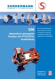
magnetically coupled centrifugal pumps - SONDERMANN Pumpen ...
magnetically coupled centrifugal pumps - SONDERMANN Pumpen ...
magnetically coupled centrifugal pumps - SONDERMANN Pumpen ...

Create successful ePaper yourself
Turn your PDF publications into a flip-book with our unique Google optimized e-Paper software.
MAGNETICALLY COUPLED<br />
CENTRIFUGAL PUMPS<br />
COMPETENCE IN<br />
PUMP AND FILTER<br />
TECHNOLOGIES
<strong>SONDERMANN</strong> MAKES THE DIFFERENCE<br />
Extremely safe products, extremely reliable service.<br />
This is our tradition. And this is why, for decades, experts<br />
have trusted in <strong>SONDERMANN</strong> products and devices. For<br />
many reasons such as …<br />
… LONG-STANDING EXPERIENCE<br />
As early as 1961, <strong>SONDERMANN</strong> supplied the first <strong>magnetically</strong><br />
<strong>coupled</strong> <strong>centrifugal</strong> pump. The technological superiority we had<br />
at that time has been our outstanding feature up to this day.<br />
Our special <strong>pumps</strong> are used in trade and industry all over the<br />
world. Many years of acquiring know-how also find expression<br />
in the services rendered for the benefit of our clients. Actually,<br />
there should be no user problem we do not resolve. This, also,<br />
is a matter of experience.<br />
... STRONG PARTNERS<br />
Working now together with FLUX-Geräte GmbH, we are even<br />
stronger than before. Our network of customer advisors has<br />
expanded and we are able to offer a wider range of problem<br />
solutions. Whatever challenge of fluid delivery you face, the job<br />
will be done best by either a <strong>SONDERMANN</strong> or a FLUX pump.<br />
Just try us.<br />
... RELIABLE SERVICE<br />
You will recognize a genuine <strong>SONDERMANN</strong> pump by its<br />
operating reliability. And it operates at your location!<br />
To achieve this, we make every effort to help you in case<br />
of need. In Germany only, especially trained advisors are<br />
available at 14 sales locations. From there we coordinate<br />
our service operations so that we arrive at your place as<br />
quick as possible.<br />
... SPECIAL DESIGNS TO MEET<br />
INDIVIDUAL DEMANDS<br />
Please do not hesitate to tell us your specific type of<br />
problem. It is a fact that standard designs often are not<br />
adequate for the use required. As a consequence, we<br />
are best prepared for special designs – and are able to<br />
realize them in no time. If we exactly know your problem,<br />
we will be able to find a way to resolve it. This is also<br />
what <strong>SONDERMANN</strong> stands for.<br />
... EXCELLENT PRODUCT QUALITY<br />
<strong>SONDERMANN</strong> is on the outside. Made in Germany is inside.<br />
All our <strong>pumps</strong> and filters are entirely manufactured in Germany.<br />
This is certainly one reason for the superior quality of our products.<br />
Since we are very serious about each pump and filter,<br />
every single one is thoroughly checked in several stages before it<br />
leaves the company – with checks down the entire characteristic<br />
curve. And of course in accordance with the ISO 9001 quality<br />
standard.<br />
<strong>SONDERMANN</strong> is a member in<br />
the association surface technology.<br />
2
TABLE OF CONTENTS<br />
Operating principle and constructional design of RM-type <strong>pumps</strong> 4 – 5<br />
Modular design; Type designation code of RM <strong>pumps</strong> 6 – 7<br />
Overview of non-self-priming <strong>pumps</strong> of the RM type 8 – 9<br />
Overview of self-priming <strong>pumps</strong> of RMS and RMB types 10<br />
RM pump of type RM-TS, safe to run dry 11<br />
RM pump of type 1, non-self-priming 12 – 13<br />
RM pump of type 1.5, non-self-priming 14 – 15<br />
RM pump of type 2, non-self-priming 16 – 17<br />
RM pump of type 2U, non-self-priming 18<br />
RM pump of type 2D, non-self-priming 19<br />
RM pump of type 3, non-self-priming 20 – 21<br />
RM pump of type 4, non-self-priming 22 – 23<br />
RM pump of type 4.5, non-self-priming 24 – 25<br />
RM pump of type 5, non-self-priming 26 – 27<br />
RMS pump of type 2.1, self-priming 28 – 29<br />
RMB pump of type 3.1, self-priming 30 – 31<br />
RM with priming tank/RM with frequency converter 32<br />
Accessories 33<br />
RM-Cool mini-pump 34 – 35<br />
Pump protectors; Flow monitors 36 – 37<br />
Sales representations in Germany and abroad 38 – 39<br />
3
THE RM MAGNETICALLY COUPLED CENTRIFUGAL PUMP WITHOUT SHAFT SEAL<br />
HIGH OPERATIONAL SAFETY, MINIMUM MAINTENANCE<br />
THE PROBLEM:<br />
It is a fact that every rotating sealing joint is wearing out<br />
with time. And if a seal breaks down in the end, fluid<br />
leaks out. Such leakage is especially dangerous with<br />
highly aggressive fluids and may result in heavy costs.<br />
When delivering non-lubricating fluids or fluids tending to<br />
crystallize in particular, the use of mechanical shaft seals<br />
requires very complex arrangements like sealing chambers<br />
with double-acting mechanical seals. These arrangements<br />
are cost-intensive and require a lot of maintenance.<br />
What is more, the necessary maintenance intervals considerably<br />
reduce the availability of the pump.<br />
THE SOLUTION:<br />
With <strong>SONDERMANN</strong> <strong>pumps</strong> of the RM type, permanent<br />
magnets convey the motor drive to the pump impeller<br />
without any contact. Thus, there is no shaft exit requiring<br />
an appropriate sealing joint. The wet part and the dry<br />
part of the pump are hermetically separated from each<br />
other by the rear casing so that leakages through worn<br />
sealings are definitely ruled out. The pump does not re -<br />
quire any maintenance since optimum sealing is ensured<br />
by no need of sealing joints at all.<br />
THE UTILIZATION:<br />
<strong>SONDERMANN</strong> RM <strong>pumps</strong> are always used when perfect<br />
leakproofness and freedom from maintenance are indispensable.<br />
They are especially used to deliver aggressive<br />
acids and bases, degreasing baths, chemicals, highly<br />
corrosive liquids or fluids tending to cristallize.<br />
Electroplating shops, printed-circuit board manufacturers,<br />
purification plants and the photographic industry profit<br />
from <strong>SONDERMANN</strong> RM <strong>pumps</strong>. Wherever conventional<br />
<strong>centrifugal</strong> <strong>pumps</strong> with complex mechanical shaft seals<br />
are required, <strong>SONDERMANN</strong> RM <strong>pumps</strong> are ideal for use.<br />
THE ADVANTAGES:<br />
• No mechanical sealing of the shaft.<br />
• Motor and pump are mechanically separated from<br />
each other.<br />
• Absolutely leakproof.<br />
• Free from maintenance.<br />
• Compact and space-saving design.<br />
• Suction and discharge nozzles are equipped with<br />
groove and O-ring sealing to assure easy installation<br />
as well as leakproof and clean piping without any<br />
leakage.<br />
4
OPERATING PRINCIPLE<br />
CONSTRUCTIONAL DESIGN OF RM-TYPE PUMPS<br />
The rear casing hermetically seals the pump chamber<br />
from the driving motor. The driving magnet rotating<br />
outside the rear casing transmits the torque of the<br />
motor to the inner magnet and thus to the impeller.<br />
The impeller is supported by sleeve bearings and a<br />
centering shaft made of high-purity oxide ceramic<br />
(99.7 %). Thus the bearing is extremely resistant to<br />
wear. The use of other bearing materials is possible.<br />
To cool and lubricate the sleeve bearings, part of the<br />
fluid delivered passes the impeller and enters the gap<br />
between the inner magnet und the rear casing. After<br />
flowing through the sleeve bearings, the fluid leaves<br />
the casing through special lubricant grooves in front<br />
of the impeller.<br />
pump<br />
housing<br />
impeller<br />
driving<br />
magnet<br />
inner magnet lantern rear casing motor<br />
starting ring of<br />
pump housing<br />
starting ring<br />
of impeller<br />
sleeve<br />
bearings<br />
starting ring<br />
of rear casing<br />
ball bearings<br />
5
MODULAR DESIGN<br />
CHOICE OF MATERIALS<br />
Whatever you want to deliver,<br />
we have the right pump for you.<br />
Metal-free and all-plastic making of our <strong>pumps</strong> is<br />
standard since this design guarantees best protection<br />
from corrosion. Housings may be also made of special<br />
stainless steel.<br />
We offer the right combination of materials for any fluid<br />
to be delivered, depending on its temperature.<br />
The following materials are available:<br />
component symbol material temperature range<br />
all components in PP polypropylene 0 to + 80 °C<br />
contact with fluid PVDF polyvinylidene fluoride -20 to + 95 °C<br />
PPS polyphenylene sulphide -20 to + 100 °C<br />
stainless steel 1.4305, 1.4571 -20 to + 100 °C<br />
oxide ceramic aluminium oxide 99.7 % -20 to + 100 °C<br />
PTFE graphite PTFE graphite -20 to + 100 °C<br />
gaskets EPDM ethylene-propylene-diene rubber -20 to + 100 °C<br />
FKM fluorinated rubber -20 to + 100 °C<br />
FEP coated perfluoroethylene/propylene copolymer -20 to + 100 °C<br />
NBR nitrile-butadiene rubber -20 to + 100 °C<br />
6
THE CHARACTERISTICS OF RM PUMPS<br />
DESIGNATION CODE OF RM PUMPS<br />
The designation code of RM <strong>pumps</strong> consists of 11 positions which<br />
refer to the materials and characteristics of every component.<br />
For example:<br />
RM PP V K K K K 7/40 15 90 1 G<br />
– 1 2 3 4 5 6 7 8 9 10 11<br />
Use the table below to put together the ideal pump for your specific needs:<br />
• = standard use / x = optionally available / - = not available<br />
no. description code material/design RM type 1 to 5<br />
RMS RMB<br />
1 1.5 2 3 4 4.5 5 2.1 3.1<br />
1 pump housing and PP polypropylene • • • • • • • - •<br />
rear casing, inner PVDF PVDF • • • • • • • • •<br />
magnet, impeller RY PPS - - - - - - - • -<br />
VA stainless steel • • - • • - - - -<br />
2 O-ring of housing V FKM • • • • • • • • •<br />
E EPDM • • • • • • • • •<br />
P NBR x x x x x x x x x<br />
T FKM FEB-coated x x x x x x x x x<br />
3 impeller starting ring K oxide ceramic 99.7 % • • • x x x x - x<br />
G PTFE graphite x x x • • • • - •<br />
4 starting rings of<br />
pump housing K oxide ceramic 99.7 % • • • • • • • • •<br />
5 sleeve bearings K oxide ceramic 99.7 % • • • • • • • • •<br />
R PPS x x x x x x x - x<br />
G PTFE graphite x x x x x x x - x<br />
P P compound x x x x x x x -<br />
6 centering shaft K oxide ceramic 99.7 % • • • • • • • • •<br />
7 pump capacity .../... see performance chart<br />
8 coupling length 15 - • • - - - - - -<br />
[in mm] 30 • - • • - - - - •<br />
45 - - • - - - - • -<br />
60 - - - • • • - - -<br />
90 - - - - • • • - -<br />
9 motor capacity .../... see performance chart<br />
10 motor 1 für 1~, 230 V ac • • • x x - - x x<br />
3 für 3~, 400 V ac x x • • • • • • •<br />
11 suction and discharge G Withworth screw-thread • • • • • • • • •<br />
parts F mounting flange x x x x x x x x x<br />
A ANSI-flange x x x x x x x x x<br />
N NPT-thread x x x x x x x x x<br />
S hose connection x x x x x x x x x<br />
7
NON-SELF-PRIMING PUMPS OF THE RM TYPE<br />
OVERVIEW<br />
1 to 30 l/min<br />
RM 1 RM 1.5<br />
up to 5 (7) m wc<br />
1 to 70 (83) l/min<br />
up to 7.5 (10) m wc<br />
RM 2<br />
5 to 118 (130) l/min<br />
up to 9 (12) m wc<br />
RM 2D<br />
5 to 60 l/min<br />
up to 16 m wc<br />
THE RIGHT PUMP FOR EVERY DELIVERY CAPACITY<br />
• Delivery rates of • Delivery heads of<br />
1 to 1,250 l/min<br />
5 to 60 m wc<br />
RM 3 RM 4 RM 4.5 RM 5<br />
8 to 200 (230) l/min<br />
up to 23 (28) m wc<br />
10 to 400 l/min<br />
up to 36 m wc<br />
20 to 900 l/min<br />
up to 32 (35) m wc<br />
30 to 1,250 l/min<br />
up to 60 m wc<br />
Figures in brackets ( ) apply to 60 Hz pump types.<br />
CHARACTERISTIC CURVES OF RM-TYPE PUMPS<br />
50 Hz<br />
• head [m wc]<br />
1450 rpm<br />
8<br />
• capacity [l/min]
TYPE DESIGNATION CODE OF RM PUMPS<br />
GENERAL OVERVIEW OF NON-SELF-PRIMING RM PUMPS<br />
RM<br />
type<br />
maximum<br />
delivery rate<br />
[l/min]<br />
maximum<br />
delivery head<br />
[m wc]<br />
maximum<br />
density<br />
[g/cm 3 ]<br />
motor<br />
capacity<br />
[kW]<br />
parts of<br />
suction and<br />
discharge<br />
material<br />
weight<br />
[kg]<br />
see<br />
page<br />
1<br />
1.5<br />
2<br />
2D<br />
3<br />
4<br />
4.5<br />
5<br />
2/20<br />
3/30<br />
5/35<br />
5/45<br />
7/55<br />
5/50<br />
7/40<br />
8/60<br />
10/100<br />
10/110<br />
16/110<br />
10/120<br />
12/150<br />
14/180<br />
16/200<br />
20/200<br />
23/200<br />
9/350<br />
18/240<br />
20/300<br />
24/340<br />
27/400<br />
30/400<br />
35/200<br />
10/550<br />
18/550<br />
23/650<br />
27/750<br />
30/850<br />
40/300<br />
45/300<br />
60/300<br />
13/1000<br />
35/1200<br />
15<br />
20<br />
30<br />
60<br />
70<br />
60<br />
70<br />
80<br />
100<br />
118<br />
60<br />
160<br />
175<br />
190<br />
200<br />
200<br />
200<br />
305<br />
310<br />
325<br />
350<br />
400<br />
400<br />
250<br />
700<br />
750<br />
833<br />
833<br />
900<br />
300<br />
300<br />
300<br />
1000<br />
1250<br />
1.7<br />
2.8<br />
4.9<br />
5.0<br />
7.5<br />
5.0<br />
6.5<br />
7.3<br />
8.4<br />
9.5<br />
16.0<br />
10<br />
13.0<br />
14.0<br />
16.2<br />
19.0<br />
23.0<br />
9.0<br />
17.5<br />
20.0<br />
24.5<br />
27.0<br />
30.0<br />
36.0<br />
9.0<br />
18.0<br />
23.0<br />
28.0<br />
32.0<br />
40.0<br />
46.0<br />
60.0<br />
13.0<br />
35.0<br />
2.5<br />
2.5<br />
1.7<br />
2.2<br />
1.25<br />
1.2<br />
2.2<br />
2.5<br />
1.3<br />
2.5<br />
1.0<br />
1.45<br />
2.0<br />
1.0<br />
1.4<br />
0.8<br />
1.1<br />
1.3<br />
1.3<br />
1.25<br />
1.8<br />
1.0<br />
1.45<br />
1.0<br />
1.25<br />
1.2<br />
1.7<br />
1.6<br />
1.25<br />
0.8<br />
1.25<br />
1.6<br />
1.0<br />
1.2<br />
1.0<br />
1.4<br />
1.1<br />
1.5<br />
1.9<br />
1.3<br />
1.8<br />
1.2<br />
1.6<br />
1.6<br />
1.25<br />
1.7<br />
1.4<br />
1.0<br />
1.15<br />
0.9<br />
1.0<br />
1.1<br />
1.25<br />
1.6<br />
1.1<br />
0.06<br />
0.06<br />
0.06<br />
0.12<br />
0.12<br />
0.09<br />
0.18<br />
0.25<br />
0.125<br />
0.25<br />
0.125<br />
0.18<br />
0.25<br />
0.18<br />
0.25<br />
0.18<br />
0.25<br />
0.25<br />
0.37<br />
0.37<br />
0.55<br />
0.37<br />
0.55<br />
0.55<br />
0.75<br />
0.75<br />
1.1<br />
1.5<br />
0.75<br />
0.75<br />
1.1<br />
1.5<br />
1.1<br />
1.5<br />
1.5<br />
2.2<br />
2.2<br />
3.0<br />
4.0<br />
3.0<br />
4.0<br />
3.0<br />
4.0<br />
2.2<br />
3.0<br />
4.0<br />
4.0<br />
5.5<br />
7.5<br />
3.0<br />
4.0<br />
5.5<br />
4.0<br />
5.5<br />
12.5<br />
G 1 1 /4 / G 1<br />
G 1 1 /4 / G 1<br />
G 1 1 /4 / G 1 1 /4<br />
G 2 / G 1 1 /2<br />
G 2 1 /4 / G 2<br />
G 2 3 /4 / G 2 1 /4<br />
G 2 3 /4 / G 2 1 /4<br />
FF d110/FF d90<br />
PP<br />
PVDF<br />
VA<br />
PP<br />
PVDF<br />
VA<br />
PP<br />
PVDF<br />
PPS<br />
PP<br />
PVDF<br />
VA<br />
PP<br />
PVDF<br />
VA<br />
PP<br />
PVDF<br />
PP<br />
PVDF<br />
2.7<br />
2.8<br />
3.4<br />
4.3<br />
4.5<br />
6.0<br />
5.2<br />
6.6<br />
6.6<br />
5.7<br />
6.6<br />
5.7<br />
6.6<br />
6.8<br />
6.6<br />
6.8<br />
6.6<br />
6.8<br />
9.0<br />
9.4<br />
9.4<br />
9.5<br />
9.4<br />
9.5<br />
9.5<br />
11.4<br />
11.4<br />
11.8<br />
14.5<br />
17.0<br />
13.0<br />
15.5<br />
18.0<br />
15.5<br />
18.0<br />
18.0<br />
27.5<br />
27.5<br />
29.0<br />
31.0<br />
29.0<br />
31.0<br />
29.0<br />
31.0<br />
28.0<br />
34.0<br />
36.0<br />
37.0<br />
47.0<br />
57.0<br />
49.0<br />
53.0<br />
57.0<br />
51.0<br />
61.0<br />
80.0<br />
12-13<br />
14-15<br />
16-18<br />
19<br />
20-21<br />
22-23<br />
24-25<br />
26-27<br />
Figures apply to 50 Hz pump types<br />
9
SELF-PRIMING PUMPS OF RMS AND RMB TYPES<br />
OVERVIEW<br />
RMS side-channel pump<br />
A pump of the RMS type is the<br />
order of the day to deliver small<br />
volume flow rates at high pressure.<br />
Delivery rate<br />
1 to 16 (22) l/min<br />
Delivery head<br />
up to 39 (54) m wc<br />
Suction head<br />
up to 7 m wc<br />
Figures in brackets ( )<br />
apply to 60 Hz pump types.<br />
RMB <strong>centrifugal</strong> pump with<br />
integrated priming tank<br />
Because of the integrated priming<br />
tank, this <strong>centrifugal</strong> pump becomes<br />
a self-priming pump with the<br />
following features:<br />
Delivery rate<br />
8 to 250 l/min<br />
Delivery head<br />
up to 18 m wc<br />
Suction head<br />
up to 3.5 m wc<br />
GENERAL OVERVIEW OF SELF-PRIMING RM PUMPS<br />
RM type maximum maximum maximum motor material weight parts of see<br />
delivery rate delivery head/ density capacity [kg] suction and page<br />
[l/min] suction head [g/cm 3 ] [kW] discharge<br />
[m wc]<br />
RMS 7 10/1<br />
9/8<br />
34/17<br />
7 12/3<br />
15 31/1<br />
16.2 38/7<br />
1.55 0.37<br />
8.5<br />
PVDF<br />
2.0 0.55 9.0<br />
1.55 0.37<br />
8.5<br />
PPS<br />
2.0 0.55 9.0 G 1 /2 28-29<br />
1.55 0.37<br />
7.5 internal<br />
PVDF<br />
2.0 0.55 8.0 thread<br />
1.55 0.37<br />
7.5<br />
PPS<br />
2.0 0.55 8.0<br />
RMB 12/175 175 12/3<br />
1.0 0.55 10.0<br />
1.4 0.75 PP 13.0 G 2 30-31<br />
15/225 225 17/3.5 1.0 0.75 PVDF 13.0 external<br />
18/250 240 18/1.0 1.2 0.75 13.0 thread<br />
10
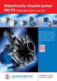
TYPE RM-TS, ABSOLUTELY SAFE TO RUN DRY<br />
NEW! ABSOLUTELY<br />
SAFE TO RUN DRY!<br />
A simple bu reliable and safe design:<br />
no sleeve bearings<br />
extremely high resistance<br />
to chemicals<br />
all existing <strong>pumps</strong> of the<br />
RM-type can be adapted to the<br />
the new system safe to run dry<br />
the <strong>pumps</strong> may be also used<br />
at high speeds without any<br />
problems<br />
increased efficiency by using<br />
bearings with an extremely<br />
small coefficient of friction<br />
The RM-TS series includes <strong>pumps</strong> from the RM2-TS type with a<br />
delivery rate of 110 l/min, 10 m wc and 90 W motor to the<br />
RM5-TS type with a delivery rate of 1,500 l/min, 60 m wc and<br />
a 15 kW motor.<br />
Technical data and dimensioned drawings of RM-TS <strong>pumps</strong> are<br />
identical with those of standard types of RM <strong>pumps</strong>, see following<br />
pages.<br />
Picture above: RM-TS type 4.5<br />
AT LAST A PUMP THAT IS ABSOLUTELY SAFE TO RUN DRY!<br />
Conventional <strong>magnetically</strong> <strong>coupled</strong> <strong>pumps</strong> can<br />
hardly cope with dry running. In fact, their sleeve<br />
bearings need continuous liquid-film lubrication<br />
to keep bearing friction and the resulting frictional<br />
heat as low as possible and also to provide the<br />
bearing with sufficient cooling.<br />
The RM-TS pump is the first <strong>magnetically</strong> <strong>coupled</strong><br />
<strong>centrifugal</strong> pump on the market that is absolutely<br />
safe to run dry.<br />
All components of the pump head that are in contact<br />
with the fluid, are still metal-free and made<br />
exclusively of materials that assure optimum chemical<br />
resistance against aggressive fluids.<br />
Since the pump does not have a shaft seal, it is<br />
hermetically sealed off and, because of this unique<br />
design, leakages through worn shaft sealings are<br />
definitely ruled out.<br />
This new series of <strong>pumps</strong> include all advantages of<br />
our longstanding experience with <strong>pumps</strong> of the<br />
RM type and the additional certainty that they will<br />
not be damaged by dry running. The coefficient<br />
of friction of the new bearing system is so small that<br />
only a minimum of heat is generated. Therefore,<br />
the bearing does not require any liquid lubrication.<br />
11
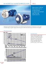
RM MAGNETICALLY COUPLED CENTRIFUGAL PUMPS<br />
TYPE 1<br />
Delivery rate up to 30 l/min<br />
Delivery head up to 4.9 (7.1) m wc<br />
No shaft seal required<br />
For aggressive and neutral liquids<br />
Made of PP, PVDF and<br />
stainless steel<br />
Protection class IP 55<br />
Figures in brackets ( )<br />
apply to 60 Hz pump types.<br />
Magnetically <strong>coupled</strong> <strong>centrifugal</strong> <strong>pumps</strong> of type 1 are non-self-priming <strong>pumps</strong> that operate in horizontal position and are made<br />
in monobloc design. A magnetic coupling connects the pump to the motor and transmits the power of the motor to the impeller.<br />
PERFORMANCE CHARTS<br />
STANDARD DESIGN<br />
water at 20 °C<br />
Housing, impeller and impeller magnet<br />
coating are made of glass-fibre re-inforced<br />
PP plastic or PVDF or stainless steel.<br />
Sleeve bearings, starting rings and centering<br />
shaft are made of 99.7 %<br />
pure oxide ceramic, and the O-ring<br />
sealing of the housing is made of either<br />
FKM or EPDM. (See table on page 7 for<br />
other materials.)<br />
Speed at 50 Hz = 2850 min -1<br />
Speed at 60 Hz = 3420 min -1<br />
Please indicate the voltage and frequency<br />
desired when placing your order.<br />
12
NON-SELF-PRIMING RM – TYPE 1<br />
TECHNICAL DATA<br />
size 2/20 3/30 5/35 7/30*<br />
maximum delivery rate [l/min] 15 20 30 30<br />
maximum delivery head [m wc] 1.7 2.8 4.9 7.1<br />
maximum density [g/cm 3 ] *** 2.5 2.5 1.7 1.25<br />
motor capacity at 50 Hz [kW] 0.060 0.060 0.060 –<br />
motor capacity at 60 Hz [kW] 0.072 0.072 0.072 0.072<br />
voltage**<br />
current rating<br />
230 V ac or 230/400 V three-phase current<br />
0.7 A with alternating current or 0.5/0.29 A with three-phase current<br />
protection class hose-proof according to IP 55<br />
ports suction side G 1 1 /4 discharge side G 1<br />
recommended maximum flow rate suction side 1 m/s discharge side 3 m/s<br />
material PP PVDF stainless steel<br />
maximum temperature 80 °C 95 °C 100 °C<br />
maximum system pressure at 20 °C 1.0 bar 2.0 bar 8.0 bar<br />
weight 2.7 kg 2.8 kg 3.4 kg<br />
* Available only in 60 Hz.<br />
** Other voltages available upon request.<br />
*** With maximum volume rate of flow. To deliver liquids with a higher relative<br />
density, the pump has to be throttled (see the following performance chart).<br />
Position of the terminal box: standard position is on top (if you need it mounted<br />
on the right or the left, please indicate when placing your order).<br />
Position of the discharge port: vertical position is standard (differing positions<br />
at 12 x 30° are possible, please indicate when placing your order).<br />
13
RM MAGNETICALLY COUPLED CENTRIFUGAL PUMPS TYPE 1.5<br />
Delivery rate up to 70 (83) l/min<br />
Delivery head up to 7.5 (10) m wc<br />
No shaft seal required<br />
For aggressive and neutral liquids<br />
Made of PP, PVDF and<br />
stainless steel<br />
Protection class IP 55<br />
Figures in brackets ( )<br />
apply to 60 Hz pump types.<br />
Magnetically <strong>coupled</strong> <strong>centrifugal</strong> <strong>pumps</strong> of type 1.5 are non-self-priming <strong>pumps</strong> that operate in horizontal position and are made<br />
in monobloc design. A magnetic coupling connects the pump to the motor and transmits the power of the motor to the impeller.<br />
PERFORMANCE CHARTS<br />
water at 20 °C<br />
STANDARD DESIGN<br />
Housing, impeller and impeller magnet coating are made of glass-fibre reinforced PP plastic or PVDF or stainless steel.<br />
Sleeve bearings, starting rings and centering shaft are made of 99.7 % pure oxide ceramic, and the O-ring sealing of<br />
the housing is made of either FKM or EPDM. (See table on page 7 for other materials.)<br />
14
NON-SELF-PRIMING RM – TYPE 1.5<br />
TECHNICAL DATA<br />
size 5/45 7/55 10/80*<br />
maximum delivery rate [l/min] 60 70 83<br />
maximum delivery head [m wc] 5,0 7.5 10.0<br />
maximum density [g/cm 3 ] *** 2,2 1.25 1.0<br />
motor capacity at 50 Hz 50 Hz [kW] 0.120 0.120 –<br />
motor capacity at 50 Hz 60 Hz [kW] 0.144 0.144 0.180<br />
voltage**<br />
current rating<br />
230 V ac or 230/400 V three-phase current<br />
0.7 A with alternating current or 0.5/0.29 A with three-phase current<br />
protection class hose-proof according to IP 55<br />
ports suction side G 1 1 /4 discharge side G 1<br />
recommended maximum flow rate suction side 1 m/s discharge 3 m/s<br />
material PP PVDF stainless steel<br />
maximum temperature 80 °C 95 °C 100 °C<br />
maximum system pressure at 20 °C 1.5 bar 2.5 bar 8.0 bar<br />
weight 4.3 kg 4.5 kg 6.0 kg<br />
* Available only in 60 Hz.<br />
** Other voltages available upon request.<br />
*** With maximum volume rate of flow. To deliver liquids with a higher relative<br />
density, the pump has to be throttled (see the following performance chart).<br />
Position of the terminal box: standard position is on top (if you need it mounted<br />
on the right or the left, please indicate when placing your order).<br />
Position of the discharge port: vertical position is standard (differing positions<br />
at 12 x 30° are possible, please indicate when placing your order).<br />
15
RM MAGNETICALLY COUPLED CENTRIFUGAL PUMPS<br />
TYPE 2<br />
Delivery rate up to 118 l/min<br />
Delivery head up to 9.5 m wc<br />
No shaft seal required<br />
For aggressive and neutral liquids<br />
Made of PP or PVDF<br />
Protection class IP 55<br />
Magnetically <strong>coupled</strong> <strong>centrifugal</strong> <strong>pumps</strong> of type 2 are non-self-priming <strong>pumps</strong> that operate in horizontal position and are made<br />
in monobloc design. A magnetic coupling connects the pump to the motor and transmits the power of the motor to the impeller.<br />
PERFORMANCE CHARTS<br />
*<br />
motor capacity<br />
[W]<br />
*<br />
*<br />
* available only as type 2U with<br />
non ventilated motor<br />
STANDARD DESIGN<br />
Housing, impeller and impeller magnet coating are made of glass-fibre reinforced<br />
PP plastic or PVDF. Sleeve bearings, starting rings and centering shaft are made<br />
of 99.7 % pure oxide ceramic, and the O-ring sealing of the housing<br />
is made of either FKM or EPDM. (See table on page 7 for other materials.)<br />
Speed at 50 Hz = 2850 min -1<br />
Speed at 60 Hz = 3420 min -1<br />
Please indicate the voltage and frequency<br />
desired when placing your order.<br />
16
NON-SELF-PRIMING RM – TYPE 2<br />
TECHNICAL DATA<br />
size 5/50 8/60 10/110<br />
maximum delivery rate [l/min] 60 80 118<br />
maximum delivery head [m wc] 5.0 7.3 9.5<br />
maximum density [g/cm 3 ] *** 2.0 1.5 2.0 1.6<br />
motor capacity at 50 Hz [kW] 0.125 0.180 0.250 0.370<br />
motor capacity at 60 Hz [kW] 0.150 0.216 0.300 0.444<br />
current rating (400 V) [A] 0.5 0.8 0.8 1.02<br />
rated speed at 50 Hz [min -1 ] 2850 2850 2850<br />
rated speed at 60 Hz [min -1 ] 3440 3440 3440<br />
weight (approx.) [kg] 5.7 6.6 6.8 7.5<br />
dimension A (ca.) [mm] 289 289 304 322<br />
dimension D (ca.) [mm] 112 112 123 123<br />
dimension H (ca.) [mm] 160.5 160.5 168 168<br />
dimension B [mm]<br />
continuously adjustable from 20 to 45 mm<br />
voltage**<br />
230 V ac or 230/400 V three-phase current<br />
protection class hose-proof according to IP 55<br />
ports suction side G 1 1 /4 discharge side G 1 1 /4<br />
recommended maximum flow rate suction side 1 m/s discharge side 3 m/s<br />
material PP PVDF<br />
maximum temperature 80 °C 95 °C<br />
maximum system pressure at 20 °C 1.0 bar 2.0 bar<br />
** Other voltages available upon request.<br />
*** With maximum volume rate of flow. To deliver liquids with a higher relative<br />
density, the pump has to be throttled (see the following performance chart).<br />
Position of the terminal box: standard position is on top (if you need it mounted<br />
on the right or the left, please indicate when placing your order).<br />
Position of the discharge port: vertical position is standard (differing positions at<br />
12 x 30° are possible, please indicate when placing your order).<br />
17
RM MAGNETICALLY COUPLED CENTRIFUGAL PUMPS<br />
TYPE 2U<br />
Delivery rate up to<br />
118 (130) l/min<br />
Delivery head up to 16 m WS<br />
(type 2D as twin pump)<br />
No shaft seal required<br />
For aggressive and neutral<br />
liquids<br />
With non-ventilated motor so<br />
that it is insensitive to vapour<br />
Made of PP or PVDF<br />
Protection class IP 55<br />
Figures in brackets ( )<br />
apply to 60 Hz pump types.<br />
size<br />
5/50<br />
7/40<br />
8/60<br />
10/100<br />
10/110<br />
12/130*<br />
maximum delivery rate [l/min]<br />
60<br />
70<br />
80<br />
100<br />
118<br />
130<br />
maximum delivery head [m wc]<br />
5.0<br />
6.5<br />
7.3<br />
8.4<br />
9.5<br />
12.0<br />
maximum density [g/cm 3 ]***<br />
1.2 2.2 2.5<br />
1.3 2.5<br />
1.0 1.45 2.0<br />
1.0 1.4<br />
0.8 1.1<br />
1.0<br />
motor capacity at 50 Hz [kW]<br />
0.09 0.18 0.25<br />
0.12 0.25<br />
0.12 0.18 0.25<br />
0.18 0.25<br />
0.18 0.25<br />
–<br />
motor capacity at 60 Hz [kW]<br />
0.108 0.216 0.30<br />
0.14 0.30<br />
0.14 0.216 0.30<br />
0.216 0.30<br />
0.216 0.30<br />
0.37<br />
current rating (400 V) [A]<br />
0.35 0.65 0.65<br />
0.45 0.65<br />
0.45 0.65 0.65<br />
0.65 0.65<br />
0.65 0.65<br />
1.02<br />
rated speed at 50 Hz [min -1 ]<br />
2850<br />
2850<br />
2850<br />
2850<br />
2850<br />
–<br />
rated speed at 60 Hz [min -1 ]<br />
3440<br />
3440<br />
3440<br />
3440<br />
3440<br />
3440<br />
weight (approx.) [kg]<br />
5.2 6.6 6.6<br />
5.7 6.6<br />
5.7 6.6 6.8<br />
6.6 6.8<br />
6.6 6.8<br />
7.5<br />
dimension A [mm]<br />
235 250 265<br />
250 265<br />
250 265 265<br />
265 265<br />
265 265<br />
310<br />
dimension B [mm]<br />
continuously adjustable from 20 to 45 mm<br />
* Available only in 60 Hz.<br />
*** With maximum volume rate of flow. To deliver liquids with a higher relative<br />
density, the pump has to be throttled (see the following performance chart).<br />
Position of the terminal box:<br />
standard position is on top<br />
(if you need it mounted on the<br />
right or the left, please indicate<br />
when placing your order).<br />
Position of the discharge port:<br />
vertical position is standard<br />
(differing positions at 12 x 30°<br />
are possible, please indicate<br />
when placing your order).<br />
18
NON-SELF-PRIMING RM – TYPE 2D<br />
This pump is equipped with a nonventilated<br />
(0.25 kW) motor with two<br />
shaft ends. A pump head of size<br />
8/60 is mounted to each side of the<br />
motor.<br />
You may use this pump as a twin pump<br />
with one driving motor to double<br />
its delivery rate to 2 x 80 l/min or<br />
as a twin pump in series connec tion<br />
(two-stage) to increase discharge<br />
pressure. Maximum delivery head<br />
then is 16 m wc.<br />
size<br />
maximum delivery rate [l/min]<br />
maximum delivery head [m wc]<br />
maximum density [g/cm 3 ] ***<br />
motor capacity at 50 Hz [kW]<br />
motor capacity at 60 Hz [kW]<br />
current rating (400 V) [A]<br />
rated speed at 50 Hz [min -1 ]<br />
rated speed at 60 Hz [min -1 ]<br />
weight (ca.) [kg]<br />
8/60<br />
2 x 80<br />
7.3<br />
1.0<br />
250<br />
300<br />
0.65<br />
2850<br />
3440<br />
8.5<br />
8/60 series connection<br />
60<br />
16<br />
1.3<br />
250<br />
300<br />
0.65<br />
2850<br />
3440<br />
9.0<br />
voltage**<br />
230 V ac or 230/400 V three-phase current<br />
protection class hose-proof according to IP 55<br />
ports suction side G 1 1 /4 discharge side G 1 1 /4<br />
recommended maximum flow rate suction side 1 m/s discharge side 3 m/s<br />
material PP PVDF<br />
maximum temperature 80 °C 95 °C<br />
maximum system pressure at 20 °C 2.5 bar 3.5 bar<br />
** Other voltages available upon request.<br />
*** With maximum volume rate of flow. To deliver liquids with a higher relative<br />
density, the pump has to be throttled (see the following performance chart).<br />
STANDARD DESIGN<br />
Housing, impeller and impeller<br />
magnet coating are made of glassfibre<br />
reinforced PP plastic or PVDF.<br />
Sleeve bearings, starting rings and<br />
centering shaft are made of 99.7 %<br />
pure oxide ceramic, and the O-ring<br />
sealing of the housing is made of<br />
either FKM or EPDM. (See table on<br />
page 7 for other materials.)<br />
19
RM MAGNETICALLY COUPLED CENTRIFUGAL PUMPS TYPE 3<br />
Delivery rate up to<br />
200 (230) l/min<br />
Delivery head up to<br />
23 (28) m wc<br />
No shaft seal required<br />
For aggressive and<br />
neutral liquids<br />
Made of PP or PVDF<br />
Protection class IP 55<br />
Figures in brackets ( )<br />
apply to 60 Hz pump types.<br />
Magnetically <strong>coupled</strong> <strong>centrifugal</strong> <strong>pumps</strong> of type 3 are non-self-priming <strong>pumps</strong> that operate in horizontal position and are made<br />
in monobloc design. A magnetic coupling connects the pump to the motor and transmits the power of the motor to the impeller.<br />
PERFORMANCE CHARTS<br />
water at 20 °C<br />
STANDARD DESIGN<br />
Housing, impeller and impeller magnet<br />
coating are made of glass-fibre reinforced<br />
PP plastic or PVDF or stainless<br />
steel. Sleeve bearings, starting rings<br />
and centering shaft are made of<br />
99.7 % pure oxide ceramic, and the<br />
O-ring sealing of the housing is made<br />
of either FKM or EPDM. (See table on<br />
page 7 for other materials.)<br />
motor capacity<br />
[W]<br />
20
NON-SELF-PRIMING RM – TYPE 3<br />
TECHNICAL DATA<br />
size<br />
10/120<br />
12/150<br />
14/180<br />
16/200<br />
20/200<br />
23/200 28/230*<br />
maximum delivery rate [l/min]<br />
160<br />
175<br />
190<br />
200<br />
200<br />
200<br />
230<br />
maximum delivery head [m wc]<br />
10<br />
13.0<br />
14.0<br />
16.5<br />
19.5<br />
23.0<br />
28<br />
maximum density [g/cm 3 ] ***<br />
1.3<br />
1.25 1.8<br />
1.0 1.45<br />
1.0 1.25<br />
1.2 1.7<br />
1.6<br />
1.5<br />
motor capacity at 50 Hz [kW]<br />
0.37<br />
0.37 0.55<br />
0.37 0.55<br />
0.55 0.75<br />
0.75 1.1<br />
1.5<br />
–<br />
motor capacity at 60 Hz [kW]<br />
0.44<br />
0.44 0.66<br />
0.44 0.66<br />
0.66 0.9<br />
0.9 1.32<br />
1.8<br />
1.8<br />
current rating (400 V) [A]<br />
1.02<br />
1.02 1.6<br />
1.02 1.6<br />
1.6 2.2<br />
2.2 2.8<br />
3.25<br />
3.25<br />
rated speed at 50 Hz [min -1 ]<br />
2900<br />
2900<br />
2900<br />
2900<br />
2900<br />
2900<br />
–<br />
rated speed at 60 Hz [min -1 ]<br />
3440<br />
3440<br />
3440<br />
3440<br />
3440<br />
3440<br />
3440<br />
dimension A [mm]<br />
350<br />
350 366<br />
350 366<br />
366 366<br />
366 385<br />
400<br />
400<br />
dimension B [mm]<br />
182<br />
182 198<br />
182 198<br />
198 198<br />
198 216<br />
230<br />
230<br />
dimension H [mm]<br />
181<br />
181 181<br />
181 181<br />
181 181<br />
181 181<br />
205<br />
205<br />
weight (PP/PVDF approx.) [kg]<br />
9.4<br />
9.4 9.5<br />
9.4 9.5<br />
9.5 11.4<br />
11.4 11.8<br />
14.5<br />
15.0<br />
voltage**<br />
230 V ac or 230/400 V three-phase current<br />
protection class hose-proof according to IP 55<br />
ports suction side G 2 discharge side G 1 1 /2<br />
recommended maximum flow rate suction side 1 m/s discharge side 3 m/s<br />
material PP PVDF stainless steel<br />
maximum temperature 80 °C 95 °C 100 °C<br />
maximum system pressure at 20 °C 2.5 bar 3.5 bar 8.0 bar<br />
* Available only in 60 Hz.<br />
** Other voltages available upon request.<br />
*** With maximum volume rate of flow. To deliver liquids with a higher relative<br />
density, the pump has to be throttled (see the following performance chart).<br />
Position of the terminal box: standard position is on top (if you need it mounted<br />
on the right or the left, please indicate when placing your order).<br />
Position of the discharge port: vertical position is standard (differing positions at<br />
12 x 30° are possible, please indicate when placing your order).<br />
21
RM MAGNETICALLY COUPLED CENTRIFUGAL PUMPS TYPE 4<br />
Delivery rate up to 400 l/min<br />
Delivery head up to 36 m wc<br />
No shaft seal required<br />
For aggressive and neutral liquids<br />
Made of PP, PVDF and<br />
stainless steel<br />
Protection class IP 55<br />
Magnetically <strong>coupled</strong> <strong>centrifugal</strong> <strong>pumps</strong> of type 4 are non-self-priming <strong>pumps</strong> that operate in horizontal position and are made<br />
in monobloc design. A magnetic coupling connects the pump to the motor and transmits the power of the motor to the impeller.<br />
PERFORMANCE CHARTS<br />
water at 20 °C<br />
STANDARD DESIGN<br />
Housing, impeller and impeller magnet<br />
coating are made of glass-fibre reinforced<br />
PP plastic or PVDF or stainless<br />
steel. Sleeve bearings, starting rings<br />
and centering shaft are made of<br />
99.7 % pure oxide ceramic, and the<br />
O-ring sealing of the housing is made<br />
of either FKM or EPDM. (See table on<br />
page 7 for other materials.)<br />
motor capacity<br />
[W]<br />
22
NON-SELF-PRIMING RM – TYPE 4<br />
TECHNICAL DATA<br />
size<br />
9/350<br />
18/240<br />
20/300<br />
24/340<br />
27/400<br />
30/400<br />
35/200<br />
maximum delivery rate [l/min]<br />
305<br />
310<br />
325<br />
350<br />
400<br />
400<br />
250<br />
maximum delivery head [m wc]<br />
9.0<br />
17.5<br />
20<br />
24.0<br />
27<br />
30<br />
36<br />
maximum density [g/cm 3 ] ***<br />
1.25<br />
0.8 1.25 1.6<br />
1.0 1.2<br />
1.0 1.4<br />
1.1 1.5 1.9<br />
1.3 1.8<br />
1.2 1.6<br />
motor capacity at 50 Hz [kW]<br />
0.75<br />
0.75 1.1 1.5<br />
1.1 1.5<br />
1.5 2.2<br />
2.2 3.0 4.0<br />
3.0 4.0<br />
3.0 4.0<br />
motor capacity at 60 Hz [kW]<br />
0.9<br />
0.9 1.32 1.8<br />
1.32 1.8<br />
1.8 2.64<br />
2.64 3.6 4.8<br />
3.6 4.8<br />
3.6 4.8<br />
current rating (400 V) [A]<br />
2.1<br />
2.2 2.8 3.25<br />
2.8 3.25<br />
3.25 4.75<br />
4.75 6.2 8.1<br />
6.2 8.1<br />
6.2 8.1<br />
rated speed at 50 Hz [min -1 ]<br />
1450<br />
2900<br />
2900<br />
2900<br />
2900<br />
2900<br />
2900<br />
rated speed at 60 Hz [min -1 ]<br />
1750<br />
3440<br />
3440<br />
3440<br />
3440<br />
3440<br />
3440<br />
dimension A [mm]<br />
430<br />
400 457 474<br />
457 474<br />
474 530<br />
530 580 580<br />
580 580<br />
580 600<br />
dimension H [mm]<br />
227<br />
220 220 220<br />
220 220<br />
220 230<br />
230 258 258<br />
258 258<br />
258 258<br />
weight (PP/PVDF approx.) [kg]<br />
17.0<br />
13.0 15.5 18.0<br />
15.5 180<br />
18.0 27.5<br />
27.5 29.0 31.0<br />
29.0 31.0<br />
29.0 31.0<br />
voltage**<br />
230 V ac or 230/400 V three-phase current<br />
protection class hose-proof according to IP 55<br />
ports suction side G 2 1 /4 discharge side G 2<br />
recommended maximum flow rate suction side 1 m/s discharge side 3 m/s<br />
material PP PVDF stainless steel<br />
maximum temperature 80 °C 95 °C 100 °C<br />
maximum system pressure at 20 °C 5.0 bar 6.0 bar 10.0 bar<br />
** Other voltages available upon request.<br />
*** With maximum volume rate of flow. To deliver liquids with a higher relative<br />
density, the pump has to be throttled (see the following performance chart).<br />
Position of the terminal box: standard position is on top (if you need it mounted<br />
on the right or the left, please indicate when placing your order).<br />
Position of the discharge port: vertical position is standard (differing positions at<br />
12 x 30° are possible, please indicate when placing your order).<br />
23
RM MAGNETICALLY COUPLED CENTRIFUGAL PUMPS TYPE 4.5<br />
Delivery rate up to 900 l/min<br />
Delivery head up to 35 m wc<br />
No shaft seal required<br />
For aggressive and neutral liquids<br />
Made of PP or PVDF<br />
Protection class IP 55<br />
Magnetically <strong>coupled</strong> <strong>centrifugal</strong> <strong>pumps</strong> of type 4.5 are non-self-priming <strong>pumps</strong> that operate in horizontal position and are made<br />
in monobloc design. A magnetic coupling connects the pump to the motor and transmits the power of the motor to the impeller.<br />
PERFORMANCE CHARTS<br />
± 10 % water at 20 °C 50 Hz<br />
STANDARD DESIGN<br />
Housing, impeller and impeller<br />
magnet coating are made of<br />
glass-fibre reinforced PP plastic<br />
or PVDF. Sleeve bearings,<br />
starting rings and centering shaft<br />
are made of 99.7 % pure oxide<br />
ceramic, and the O-ring sealing<br />
of the housing is made of either<br />
FKM or EPDM. (See table on<br />
page 7 for other materials.)<br />
motor capacity [W]<br />
± 10 % water at 20 °C 50 Hz<br />
24
NON-SELF-PRIMING RM – TYPE 4.5<br />
TECHNICAL DATA<br />
size<br />
10/550<br />
18/550<br />
23/650<br />
27/750<br />
30/850<br />
35/800*<br />
maximum delivery rate [l/min]<br />
700<br />
750<br />
833<br />
833<br />
900<br />
900<br />
maximum delivery head [m wc]<br />
9.0<br />
18.0<br />
23,0<br />
28,0<br />
32<br />
35<br />
maximum density [g/cm 3 ] ***<br />
1.6<br />
1.25 1.7<br />
1.4<br />
1.0<br />
1.15<br />
1.0<br />
motor capacity at 50 Hz [kW]<br />
2.2<br />
3.0 4.0<br />
4.0<br />
5.5<br />
7.5<br />
–<br />
motor capacity at 60 Hz [kW]<br />
2.6<br />
3.6 4.8<br />
4.8<br />
6.6<br />
9.0<br />
6.6<br />
current rating (400 V) [A]<br />
4.9<br />
6.25 8.1<br />
8.1<br />
11.0<br />
14.5<br />
13.8<br />
rated speed at 50 Hz [min -1 ]<br />
1450<br />
2900<br />
2900<br />
2900<br />
2900<br />
–<br />
rated speed at 60 Hz [min -1 ]<br />
1750<br />
3440<br />
3440<br />
3440<br />
3440<br />
3440<br />
weight [kg]<br />
28.0<br />
34.0 36.0<br />
37.0<br />
47.0<br />
57.0<br />
48.5<br />
voltage**<br />
230 V ac or 230/400 V three-phase current<br />
protection class hose-proof according to IP 55<br />
ports suction side G 2 3 /4 discharge side G 2 1 /4<br />
recommended maximum flow rate suction side 1 m/s discharge side 3 m/s<br />
material PP PVDF<br />
maximum temperature 80 °C 95 °C<br />
maximum system pressure at 20 °C 5.0 bar 6.0 bar<br />
* Available only in 60 Hz.<br />
** Other voltages available upon request.<br />
*** With maximum volume rate of flow. To deliver liquids with a higher relative<br />
density, the pump has to be throttled (see the following performance chart).<br />
dimensions for standard<br />
motor up to 4.0 kW<br />
dimensions for standard<br />
motor up to 7.5 kW<br />
Position of the terminal box: standard position is on top (if you need it mounted<br />
on the right or the left, please indicate when placing your order).<br />
Position of the discharge port: vertical position is standard (differing positions at<br />
12 x 30° are possible, please indicate when placing your order).<br />
25
RM MAGNETICALLY COUPLED CENTRIFUGAL PUMPS TYPE 5<br />
Delivery rate up to 1.250 l/min<br />
Delivery head up to 60 m wc<br />
No shaft seal required<br />
For aggressive and neutral liquids<br />
Made of PP or PVDF<br />
Protection class IP 55<br />
Magnetically <strong>coupled</strong> <strong>centrifugal</strong> <strong>pumps</strong> of type 5 are non-self-priming <strong>pumps</strong> that operate in horizontal position and are made<br />
in monobloc design. A magnetic coupling connects the pump to the motor and transmits the power of the motor to the impeller.<br />
PERFORMANCE CHARTS<br />
± 10 % water at 20 °C 50 Hz<br />
STANDARD DESIGN<br />
Housing, impeller and impeller magnet<br />
coating are made of glass-fibre reinforced<br />
PP plastic or PVDF. Sleeve bearings,<br />
starting rings and centering shaft are<br />
made of 99.7 % pure oxide ceramic,<br />
and the O-ring sealing of the housing<br />
is made of either FKM or EPDM.<br />
(See table on page 7 for other materials.)<br />
motor capacity [W]<br />
± 10 % water at 20 °C 50 Hz<br />
26
NON-SELF-PRIMING RM – TYPE 5<br />
TECHNICAL DATA<br />
size<br />
40/300<br />
45/300<br />
60/300<br />
13/1000<br />
35/1200<br />
maximum delivery rate [l/min]<br />
300<br />
300<br />
300<br />
1000<br />
1250<br />
maximum delivery head [m wc]<br />
40<br />
45<br />
60<br />
13<br />
35<br />
maximum density [g/cm 3 ] ***<br />
0.9<br />
1.0<br />
1.1<br />
1.25 1.6<br />
1.1<br />
motor capacity a 50 Hz [kW]<br />
3.0<br />
4.0<br />
5.5<br />
4.0 5.5<br />
12.5<br />
motor capacity a 60 Hz [kW]<br />
3.6<br />
4.8<br />
6.6<br />
4.8 6.6<br />
15.0<br />
current rating (400 V) [A]<br />
6.25<br />
8.1<br />
11.0<br />
8.1 11.0<br />
24.0<br />
rated speed at 50 Hz [min -1 ]<br />
2900<br />
2900<br />
2900<br />
1450 1450<br />
2900<br />
rated speed at 60 Hz [min -1 ]<br />
3440<br />
3440<br />
3440<br />
1750 1750<br />
3440<br />
ports suction side<br />
G2 3 /4<br />
G2 3 /4<br />
G2 3 /4<br />
FF d110<br />
FF d110<br />
FF d110<br />
ports discharge side<br />
G2 1 /4<br />
G2 1 /4<br />
G2 1 /4<br />
FF d90<br />
FF d90<br />
FF d90<br />
weight when made of PP approx. [kg]<br />
49<br />
53<br />
57<br />
51 61<br />
80<br />
weight when made of PVDF approx. [kg]<br />
56<br />
60<br />
66<br />
52 69<br />
90<br />
dimension A [mm]<br />
619<br />
625<br />
692<br />
680 740<br />
780<br />
dimension H [mm]<br />
316<br />
316<br />
331<br />
– –<br />
–<br />
dimension D [mm]<br />
194<br />
220<br />
250<br />
220 250<br />
260<br />
voltage**<br />
230 V ac or 230/400 V three-phase current<br />
protection class hose-proof according to IP 55<br />
recommended maximum flow rate suction side 1 m/s discharge side 3 m/s<br />
material PP PVDF<br />
maximum temperature 80 °C 95 °C<br />
maximum system pressure at 20 °C 6.0 bar 6.0 bar<br />
RM 13/1000 - 35/1200<br />
** Other voltages available<br />
upon request.<br />
*** With maximum volume rate<br />
of flow. To deliver liquids<br />
with a higher relative<br />
density, the pump has to be<br />
throttled (see the following<br />
performance chart).<br />
RM 40/300 - 60/300<br />
Position of the terminal box:<br />
standard position is on top<br />
(if you need it mounted on<br />
the right or the left, please<br />
indicate when placing your<br />
order).<br />
Position of the discharge port:<br />
vertical position is standard<br />
(differing positions at 12 x 30°<br />
are possible, please indicate<br />
when placing your order).<br />
27
RM MAGNETICALLY COUPLED CENTRIFUGAL PUMPS<br />
TYPE RMS<br />
Self-priming<br />
side-channel pump<br />
Delivery rate up to<br />
16 (21) l/min<br />
Delivery head up to<br />
39 (54) m wc<br />
No shaft seal required<br />
For aggressive and neutral liquids<br />
Made of PPS or PVDF<br />
Protection class IP 55<br />
Figures in brackets ( )<br />
apply to 60 Hz pump types.<br />
PERFORMANCE CHARTS<br />
delivery rate at 50 Hz<br />
delivery rate at 50 Hz<br />
water at 20° water at 20°<br />
28
SEL-PRIMING RMS TYPE 2.1<br />
TECHNICAL DATA<br />
size<br />
design<br />
maximum delivery rate [l/min]<br />
maximum delivery head [m wc]<br />
max. suction head at 20 °C [m wc]<br />
maximum temperature [°C]<br />
maximum density [g/cm 3 ]<br />
motor capacity at 50 Hz [kW]<br />
motor capacity at 60 Hz [kW]<br />
current rating (400 V) [A]<br />
rated speed at 50 Hz [min -1 ]<br />
rated speed at 60 Hz [min -1 ]<br />
weight approx. [kg]<br />
9/8<br />
PPS PVDF PPS PVDF PPS PVDF<br />
7 7 7 7 7 7<br />
12 10 12 10 12 10<br />
3.0 1.0 3.0 1.0 3.0 1.0<br />
100 80 100 80 100 80<br />
1.55 1.35 2.0<br />
0.37 0.37 0.55<br />
0.44 0.44 0.66<br />
0.7 0.7 1.0<br />
1400 1400 1400<br />
1700 1700 1700<br />
8.5 8.0 9.0<br />
34/17<br />
PPS PVDF PPS PVDF PPS PVDF<br />
16 15 16 15 16 15<br />
39 31 39 31 39 31<br />
7.0 1.0 7.0 1.0 7.0 1.0<br />
100 80 100 80 100 80<br />
1.55 1.35 2.0<br />
0.37 0.37 0.55<br />
0.44 0.44 0.66<br />
1.0 1.0 1.5<br />
2800 2800 2800<br />
3400 3400 3400<br />
7.5 7.0 8.0<br />
voltage**<br />
230 V ac or 230/400 V three-phase current<br />
protection class hose-proof according to IP 55<br />
ports suction side IG 1 /2 discharge side IG 1 /2<br />
material (design) PPS PVDF<br />
housing section PPS PVDF<br />
impeller PPS oxide ceramic 99,7 %<br />
lantern PP PP<br />
inner magnet coating PPS or PP PVDF<br />
centering shaft, starting ring oxide ceramic 99,7 % oxide ceramic 99,7 %<br />
sleeve bearings oxide ceramic 99,7 % oxide ceramic 99,7 %<br />
** Other voltages available upon request.<br />
internal thread<br />
Position of the terminal box: standard position is on top (if you need it mounted on the right or the left,<br />
please indicate when placing your order).<br />
29
RM MAGNETICALLY COUPLED CENTRIFUGAL PUMPS<br />
TYPE RMB<br />
Centrifugal pump with<br />
integrated priming tank<br />
Delivery rate up to 240 l/min<br />
Delivery head up to 18 m wc<br />
No shaft seal required<br />
For aggressive and<br />
neutral liquids<br />
Made of PP or PVDF<br />
Protection class IP 55<br />
Magnetically <strong>coupled</strong> <strong>centrifugal</strong> <strong>pumps</strong> of the RMB type are self-priming <strong>pumps</strong> with integrated priming tanks. They are made<br />
of plastic, built in monobloc design and operate in horizontal position. A magnetic coupling connects the pump to the motor<br />
and transmits the power of the motor to the impeller.<br />
PERFORMANCE CHARTS<br />
water at 20 °C<br />
STANDARD DESIGN<br />
Housing, impeller and impeller magnet<br />
coating are made of glass-fibre reinforced<br />
PP plastic or PVDF. Sleeve bearings,<br />
starting rings and centering shaft are<br />
made of 99.7% pure oxide ceramic,<br />
and the O-ring sealing of the housing<br />
is made of either FKM or EPDM.<br />
(See table on page 7 for other materials.)<br />
motor capacity<br />
[W]<br />
30
SELF-PRIMING RMB TYPE 3.1<br />
TECHNICAL DATA<br />
size<br />
12/175<br />
15/225<br />
18/250<br />
maximum delivery rate [l/min]<br />
175<br />
225<br />
240<br />
maximum delivery head [m wc]<br />
12<br />
15<br />
18<br />
max. suction head at 20 °C [m wc]<br />
3.0<br />
3,5<br />
1.0<br />
maximum density [g/cm 3 ] ***<br />
1.3 1.8<br />
1.2<br />
1.0<br />
motor capacity at 50 Hz [kW]<br />
0.55 0.75<br />
0.75<br />
0.75<br />
motor capacity at 60 Hz [kW]<br />
0.66 0.9<br />
0.9<br />
0.9<br />
current rating (400 V) [A]<br />
1.6 2.2<br />
2.2<br />
2.2<br />
rated speed at 50 Hz [min -1 ]<br />
2800 2800<br />
2800<br />
2800<br />
rated speed at 60 Hz [min -1 ]<br />
3400 3400<br />
3400<br />
3400<br />
parts suction side<br />
G2<br />
G2<br />
G2<br />
G2<br />
ports discharge side<br />
G2<br />
G2<br />
G2<br />
G2<br />
weight approx. [kg]<br />
10 13<br />
13<br />
13<br />
dimension A [mm]<br />
490 500<br />
500<br />
500<br />
voltage**<br />
230 V ac or 230/400 V three-phase current<br />
protection class house-proof according to IP 55<br />
recommended maximum flow rate suction side 1 m/s discharge side 3 m/s<br />
materials PP PVDF<br />
maximum temperature 65 °C 85 °C<br />
maximum system pressure at 20 °C 2.5 bar 3.5 bar<br />
** Other voltages available upon request.<br />
*** With maximum volume rate of flow. To deliver liquids with a higher relative<br />
density, the pump has to be throttled (see the following performance chart).<br />
motor with<br />
terminal box<br />
rotating by 90°<br />
M8 mounting slot<br />
maximum distance of mounting<br />
screws = 49 mm<br />
Position of the terminal box: standard position is on top (if you need it mounted on the right or the left,<br />
please indicate when placing your order).<br />
31
RM PUMP WITH EXTRA PRIMING TANK<br />
TYPE RM<br />
Inlet Port<br />
All non-self-priming <strong>pumps</strong> of the RM type may<br />
be combined with an extra priming tank to be<br />
self-priming as well.<br />
<strong>SONDERMANN</strong> supplies you with the whole<br />
installation completely mounted to a base plate.<br />
Priming tanks are available in different sizes ranging<br />
from 5 to 50 litres. When arranging the design,<br />
make sure that the volume of the priming tank is<br />
about 1.5 times larger than the overall volume of<br />
the suction-pipe runs to be evacuated.<br />
base plate<br />
material<br />
volume<br />
dimensions<br />
pump<br />
thread size<br />
A<br />
B<br />
PP PVDF PVC<br />
litres<br />
C D Ø E<br />
type<br />
suction side F discharge side G<br />
600 250<br />
x x x<br />
5<br />
310 250 200<br />
1<br />
G 1 1 /4“ G 1“<br />
600 270<br />
x x x<br />
5<br />
310 250 200<br />
1.5<br />
G 1 1 /4“ G 1“<br />
600 270<br />
x x x<br />
10<br />
560 500 200<br />
1.5<br />
G 1 1 /4“ G 1“<br />
600 270<br />
x x x<br />
10<br />
560 500 200<br />
2<br />
G 1 1 /4“ G 1 1 /4“<br />
600 270<br />
x x x<br />
15<br />
810 750 200<br />
2<br />
G 1 1 /4“ G 1 1 /4“<br />
1000 270<br />
x x x<br />
15<br />
810 750 200<br />
3<br />
G 2“ G 1 1 /2“<br />
1000 270<br />
x x x<br />
20<br />
1060 1000 200<br />
3<br />
G 2“ G 1 1 /2“<br />
1000 300<br />
x<br />
30<br />
890 790 250<br />
3<br />
G 2“ G 1 1 /2“<br />
1000 300<br />
x<br />
25<br />
790 690 250<br />
4<br />
G 2 1 /4“ G 2“<br />
1000 300<br />
x<br />
30<br />
890 790 250<br />
4<br />
G 2 1 /4“ G 2“<br />
1200 300<br />
x<br />
30<br />
890 790 250<br />
4.5<br />
G 2 3 /4“ G 2 1 /4“<br />
1200 400<br />
x<br />
50<br />
1175 1075 300<br />
4.5<br />
G 2 3 /4“ G 2 1 /4“<br />
RM PUMP WITH INTEGRATED FREQUENCY CONVERTER<br />
IF SEVERAL DELIVERY RATES ARE REQUIRED<br />
SPEED CONTROL IS USED TO PRECISELY SET<br />
THE OPERATING POINT DESIRED.<br />
Features:<br />
• Power ranges: 0.37 to 1.1 kW<br />
• Voltage: 230 V single-phase, 50 or 60 Hz<br />
• The speed rate is set either by a signal of an imposed<br />
control unit or by the control panel mounted to the motor.<br />
• The frequency converter is perfectly tuned to the<br />
characteristic of the pump.<br />
• This operating principle saves much energy in contrast to<br />
adjusting delivery rates by means of flow-control valves.<br />
32
ACCESSORIES AND OPTIONAL EQUIPMENT TO RM PUMPS<br />
ACCESSORIES TO THE MOTOR<br />
pilotherm or PTC thermistor<br />
ON/OFF switch with cable 2.5 m long and plug (only with 230 V ac)<br />
protective motor switch with ON/OFF switch, mounted and wired to the terminal box<br />
three-phase connection cable 5 m long with CEE plug of 5 x 16 A, completely installed<br />
O-RING SEALINGS TO SUCTION AND DISCHARGE PORTS<br />
type<br />
O-ring to suction side<br />
[mm]<br />
O-ring to discharge side<br />
[mm]<br />
FKM<br />
EPDM<br />
FEP-coated<br />
FKM<br />
1, 1.5<br />
26 x 3.5 mm<br />
21 x 3.0 mm<br />
X<br />
X<br />
X<br />
2<br />
30 x 3 mm<br />
26 x 3.5 mm<br />
X<br />
X<br />
X<br />
3<br />
48 x 3.5 mm<br />
31.35 x 3.53 mm<br />
X<br />
X<br />
X<br />
3.1<br />
40.6 x 5.3 mm<br />
40.6 x 5.3 mm<br />
X<br />
X<br />
X<br />
4<br />
53.5 x 3.5 mm<br />
40 x 5 mm<br />
X<br />
X<br />
X<br />
4.5<br />
65 x 4 mm<br />
47 x 5.3 mm<br />
X<br />
X<br />
X<br />
THREE-PIECE HOSE CONNECTIONS WITH SPIGOT NUT AND HOSE NIPPLE INCLUDING O-RINGS<br />
thread size<br />
hose<br />
nipple<br />
suitable for suction ports of<br />
the following pump types<br />
suitable for suction ports of<br />
the following pump types<br />
PP<br />
material<br />
PVDF<br />
material<br />
G 1<br />
18<br />
21<br />
1, 1.5<br />
X<br />
X<br />
18<br />
G 1 1 /4<br />
21<br />
1, 1.5, 2<br />
2<br />
X<br />
X<br />
26<br />
30<br />
1“<br />
G 1 1 /2<br />
1 1 /4“<br />
3<br />
X<br />
X<br />
1 1 /2“<br />
1“<br />
G 2<br />
1 1 /4“<br />
3, 3.1<br />
3.1, 4<br />
X<br />
X<br />
1 1 /2“<br />
2 “<br />
G 2 1 /4<br />
1 1 /2“<br />
2 “<br />
4<br />
4.5<br />
X<br />
X<br />
FLANGES TO SCREW ONTO THREADED PORTS INCLUDING O-RINGS<br />
one set = 1 flange to the suction side, 1 flange to the discharge side<br />
type<br />
nominal diameter of<br />
suction part<br />
nominal diameter of<br />
discharge part<br />
PP<br />
material<br />
PVDF<br />
material<br />
2<br />
DN 20 PN 10<br />
DN 20 PN 10<br />
X<br />
X<br />
3<br />
DN 32 PN 10<br />
DN 25 PN 10<br />
X<br />
X<br />
4<br />
DN 50 PN 10<br />
DN 40 PN 10<br />
X<br />
X<br />
5<br />
DN 65 PN 10<br />
DN 50 PN 10<br />
X<br />
X<br />
We also offer you a wide range of accessories to perfectly complete the installation of <strong>SONDERMANN</strong> <strong>pumps</strong>.<br />
These accessories include, for example, plastic spigot nuts, hose nipples, plastic screws, filter plates, suction screen<br />
filters, differential pressure switches etc. Do not hesitate to ask us for advice! We would be glad to help you.<br />
33
MAGNETICALLY COUPLED CENTRIFUGAL MINI-PUMP<br />
TYPE RM-COOL<br />
TYPE 0.5<br />
Brushless electronically<br />
controlled motor<br />
Adjustable speed of<br />
1 to 3,240 min -1<br />
For short-term and<br />
continuous operation<br />
Made of PPS, PP and PVDF<br />
Delivery rate up to 5 l/min<br />
Delivery head up to 2 m wc<br />
No shaft seal required<br />
The <strong>magnetically</strong> <strong>coupled</strong> <strong>centrifugal</strong> mini-pump of the RM-Cool type 0.5 is the ideal<br />
high-performance cooling system to absolutely reliably remove heat from laser devices<br />
and computers and is also used in process engineering and solar energy technology etc.<br />
PERFORMANCE CHARTS<br />
water at 20 °C<br />
34
RM-COOL TYPE 0.5<br />
TECHNICAL DATA<br />
motor<br />
voltage<br />
motor capacity<br />
brushless electronically controlled motor<br />
12, 24 or 48 V dc; direct connection to the power supply unit of a PC, for example<br />
7 Watt<br />
speed adjustable from 1 to 3240 min -1<br />
delivery rate<br />
delivery head<br />
up to 5 l /min<br />
up to 2 m wc<br />
ports suction side/discharge side G 1 / 8 ”<br />
materials<br />
bearings<br />
sealing<br />
PPS, PP or PVDF<br />
oxide ceramic<br />
FKM, EPDM or NBR<br />
temperature range up to 100 °C<br />
weight<br />
approx. 175 – 215 g<br />
Outlet G1/8<br />
Inlet G1/8<br />
electrical connection<br />
35
ELECTRONIC PROTECTION<br />
FOR MAGNETICALLY COUPLED<br />
CENTRIFUGAL PUMPS<br />
Electronic monitoring of motor currents protects the<br />
pump from dry running, overheating and overload.<br />
If the above mentioned operating states are not absolutely<br />
impossible with your installation, you should use<br />
an electronic process monitor to switch off the pump<br />
before it is damaged. Such monitors will not only avoid<br />
damage to the pump, but also downtime and costs<br />
resulting<br />
thereof. At the same time, the monitor checks the<br />
pumping process for the set delivery rate. Once the<br />
cause of a malfunction is eliminated, the pump is<br />
immediately ready to continue operation. The process<br />
monitor is easy to install into the pump’s power supply<br />
unit. As it is not necessary to build it into pipe runs,<br />
this process monitor also is ideal to retrofit existing<br />
installations. Four different types of process monitors<br />
are available:<br />
RPR CONTROL 100-1<br />
to be built into control cabinets (mounted on top-hat rail)<br />
without programming unit.<br />
RPR CONTROL 100-2<br />
to be built into control cabinets (mounted on top-hat rail)<br />
with integrated programming unit.<br />
RPR Control 100-1 RPR Control 100-2<br />
RPR CONTROL 100-3<br />
Field device with power section of up to 4.0 kW (up to<br />
7.5 kW optionally available), mounted in an IP 65 casing<br />
for installation in the field (e.g. at the filter), complete with<br />
indicating lamps and push-button but without programming unit.<br />
SEPARATE PROGRAMMING UNIT<br />
RPR-Control 100-3<br />
Hand-held appliance with cable and plug to programme the<br />
switching thresholds of RPR-Control 100-1 and RPR-Control 100-3.<br />
FUNCTION<br />
An overload controller with analogue output monitors the actual<br />
power of the pump motor. There are four switching thresholds<br />
defined:<br />
• dry-running (fault, the motor is switched off);<br />
• overheating (fault, the motor is switched off);<br />
• overload (fault, the motor is switched off);<br />
• filter contaminated (warning).<br />
seperate programming unit<br />
The switching thresholds are user-programmable.<br />
Also included is a real-time clock with elapsedtime<br />
meter, e. g. to monitor maintenance intervals.<br />
36
FLOW MONITORS<br />
FOR SIMPLE AND COST-EFFECTIVE<br />
MONITORING<br />
Characteristics:<br />
• The housing is made of polypropylene or PVDF.<br />
Flow monitors are to be built into the discharge<br />
pipes of <strong>magnetically</strong> <strong>coupled</strong> <strong>centrifugal</strong> <strong>pumps</strong><br />
of types 2 to 4.<br />
• Every flow monitor has an integrated float switch<br />
and a reed contact. A spigot nut at the inlet side<br />
of the flow monitor is used to screw it to an external<br />
thread with O-ring sealing.<br />
• The outlet side of the flow monitor is equipped<br />
with a grooved external thread to take the O-ring<br />
seal. The necessary O-rings are optionally available.<br />
When ordering a flow monitor, please indicate<br />
the density of the fluid delivered.<br />
type<br />
size<br />
PP material<br />
PVDF material<br />
O-ring<br />
FKM material<br />
EPDM material<br />
2<br />
d 25 DN 20 – G 1 1 /4“<br />
x<br />
x<br />
26 x 3,5<br />
x<br />
x<br />
3 d 32 DN 25 – G 1 1 /2“ x<br />
x<br />
31,35 x 3,53<br />
x<br />
x<br />
4 d 40 DN 32 – G 2“<br />
x<br />
x<br />
40,6 x 5,3<br />
x<br />
x<br />
The standard PP design is suitable to deliver low-viscosity fluids resembling water with densities of 0.8 to 1.5.<br />
The standard PVDF design is suitable to deliver low-viscosity fluids resembling water with densities of 0.8 to 1.84.<br />
Electrical switchgear<br />
wired within an ISO housing including contactor, relays and hand-actuated switches, suitable for all sizes.<br />
Electrical switchgear as above<br />
but in addition with built-in time-limit relay to be manually adjusted.<br />
The wiring of the flow monitor to the electrical switchgear is provided by the customer and not included<br />
in the scope of delivery.<br />
37
SALES AREAS IN GERMANY<br />
Thanks to our wide distribution network all over Germany,<br />
you will always find <strong>SONDERMANN</strong> <strong>pumps</strong> at close range.<br />
1 Berlin/Brandenburg<br />
<strong>SONDERMANN</strong> <strong>Pumpen</strong> + Filter<br />
GmbH & Co. KG<br />
August-Horch-Straße 4, 51149 Köln<br />
Phone: 0 22 03/93 94-0<br />
Fax: 0 22 03/93 94-48<br />
info@sondermann-pumpen.de<br />
2 Hamburg/Schleswig-Holstein<br />
Rolf-Dieter Thelen<br />
Falkenweg 9, 25337 Elmshorn<br />
Phone: 0 41 21/725 93<br />
Fax: 0 41 21/725 93<br />
Mobil: 0172/628 77 82<br />
r.thelen@flux-pumpen.de<br />
3 Hannover/Kassel<br />
Dipl.-Ing. (FH) Ulrich Pöhls<br />
Alte Bemeroder Straße 122<br />
30539 Hannover<br />
Phone: 0 5 11/51 71 51<br />
Fax: 0 5 11/544 59 29<br />
Mobil: 0172/628 77 83<br />
u.poehls@flux-pumpen.de<br />
4 Bremen/Münster<br />
Dipl.-Ing. (FH) Dieter Röder<br />
Sögelner Str. 5, 49565 Bramsche<br />
Phone: 0 54 61/96 90 20<br />
Fax: 0 54 61/96 90 21<br />
Mobil: 0170/180 25 46<br />
d.roeder@flux-pumpen.de<br />
5.1 Nordrhein-Westfalen Nord<br />
Stephan Hill<br />
Wilensteinweg 10, 50739 Köln<br />
Phone: 0 22 03/93 94-20<br />
Fax: 0 22 03/93 94-48<br />
Mobil: 0173/716 28 44<br />
s.hill@sondermann-pumpen.de<br />
5.2 Nordrhein-Westfalen Süd<br />
Waldemar Wostmann<br />
Mattlener Weg 12, 50769 Köln<br />
Phone: 02 21/708 81 92<br />
Fax: 02 21/700 40 96<br />
Mobil: 0177/708 81 92<br />
pumpeninfo@wostmann.de<br />
6 Hessen<br />
Robert Höfling<br />
Odenwaldring 25<br />
63500 Seligenstadt<br />
Phone: 0 61 82/15 83<br />
Fax: 0 61 82/96 19 27<br />
Mobil: 0177/583 49 69<br />
r.hoefling@flux-pumpen.de<br />
7.1 Stuttgart/Ulm<br />
Horst Laidig<br />
Buchfinkenweg 7, 70563 Stuttgart<br />
Phone: 0 7 11/780 11 29<br />
Fax: 0 7 11/780 43 29<br />
Mobil: 0172/407 39 40<br />
h.laidig@flux-pumpen.de<br />
7.2 Baden-Württemberg Süd<br />
Dipl.-Ing. (FH) Zdenko Hrncjar<br />
Vogesenstraße 1b, 79331 Teningen<br />
Phone: 0 76 41/933 51 14<br />
Fax: 0 76 41/933 51 16<br />
Mobil: 0172/101 42 17<br />
z.hrncjar@flux-pumpen.de<br />
7.3 Baden-Württemberg West<br />
Martin Reichert<br />
Talweg 12, 75433 Maulbronn<br />
Phone: 0 70 43/101-420<br />
Fax: 0 70 43/101-444<br />
Mobil: 0174/166 57 62<br />
m.reichert@flux-pumpen.de<br />
8 Bayern Süd<br />
Markus Werner<br />
Hauptstraße 5a, 82544 Egling<br />
Phone: 0 81 76/15 45<br />
Fax: 0 81 76/99 70 23<br />
Mobil: 0172/831 15 96<br />
m.werner@flux-pumpen.de<br />
9 Bayern Nord<br />
Dipl.-Ing. (FH) W. Schauer<br />
Margaretenweg 3<br />
91166 Georgensgmünd<br />
Phone: 0 91 72/77 52<br />
Fax: 0 91 72/70 01 28<br />
Mobil: 0172/628 77 81<br />
w.schauer@flux-pumpen.de<br />
10 Rheinland-Pfalz/Saarland<br />
Frank Schorn<br />
Fliederstraße 19,<br />
66773 Schwalbach<br />
Phone: 0 68 34/56 72 50<br />
Fax: 0 68 34/56 72 62<br />
Mobil: 0172/625 92 23<br />
f.schorn@flux-pumpen.de<br />
15 Thüringen/Sachsen-Anhalt<br />
Dipl. Ing. (FH) Hendrik Müller<br />
Angerstraße 4, 06193 Götschetal<br />
Phone: 0 34 606/29 03 21<br />
Fax: 0 34 606/29 03 22<br />
Mobil: 0172/132 46 74<br />
h.mueller@flux-pumpen.de<br />
16 Sachsen<br />
Dipl.-Ing. Gerd Hanauska<br />
Wasserschänkenstraße 32<br />
09247 Chemnitz/Röhrsdorf<br />
Phone: 0 37 22/50 25 75<br />
Fax: 0 37 22/50 56 03<br />
Mobil: 0172/628 77 84<br />
g.hanauska@flux-pumpen.de<br />
17 Mecklenburg/Vorpommern<br />
Rolf-Dieter Thelen<br />
Falkenweg 9<br />
25337 Elmshorn<br />
Phone: 0 41 21/725 93<br />
Fax: 0 41 21/725 93<br />
Mobil: 0172/628 77 82<br />
r.thelen@flux-pumpen.de<br />
38
SALES REPRESENTATIONS ABROAD<br />
<strong>SONDERMANN</strong> <strong>pumps</strong><br />
are present all over the world.<br />
Are you looking for an opportunity<br />
to buy our products in your country?<br />
Just give us a call at our Cologne<br />
headquarters.<br />
We will be pleased to help you.<br />
<strong>SONDERMANN</strong><br />
PUMPEN + FILTER GMBH & Co. KG<br />
August-Horch-Strasse 4<br />
D-51149 Cologne<br />
Phone: +49 22 03/93 94-0<br />
Fax: +49 22 03/93 94-48<br />
info@sondermann-pumpen.de<br />
www.sondermann-pumpen.de<br />
INNOVATORS IN<br />
FLOW TECHNOLOGY<br />
For more than 40 years, <strong>SONDERMANN</strong>’s<br />
specialist consultants have also advised<br />
you on the comprehensive range of FLUX<br />
<strong>pumps</strong> and their accessories. FLUX covers<br />
all ranges of laboratory, barrel, container<br />
and thick matter <strong>pumps</strong>, pneumatic diaphragm<br />
<strong>pumps</strong> and liquid volume meters.<br />
We invite you to also benefit from this<br />
wide-range competence for doing a good<br />
job. For more information visit us at<br />
www.flux-pumpen.de<br />
39
SRM 11/08 – 3E<br />
<strong>SONDERMANN</strong><br />
PUMPEN + FILTER GMBH & Co. KG<br />
August-Horch-Straße 4 ·<br />
D-51149 Cologne<br />
Phone +49 (0) 22 03/93 94-0<br />
Fax +49 (0) 22 03/93 94-48<br />
info@sondermann-pumpen.de<br />
www.sondermann-pumpen.de<br />
Subject to technical alterations