operation instruction - SONDERMANN Pumpen + Filter GmbH & Co ...
operation instruction - SONDERMANN Pumpen + Filter GmbH & Co ...
operation instruction - SONDERMANN Pumpen + Filter GmbH & Co ...

Create successful ePaper yourself
Turn your PDF publications into a flip-book with our unique Google optimized e-Paper software.
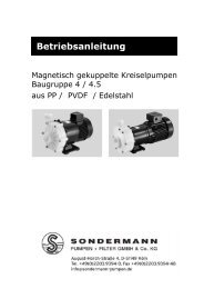
OPERATION INSTRUCTION<br />
Magnetically <strong>Co</strong>upled Centrifugal Pumps<br />
of Types RM 4 / 4.5<br />
Made of PP / PVDF<br />
<strong>SONDERMANN</strong> PUMPEN + FILTER GMBH & <strong>Co</strong>. KG, D-51149 KÖLN<br />
Tel.: +49-2203-9304-0, Fax: +49-2203-9394-48, E-Mail: info@sondermann-pumpen.de
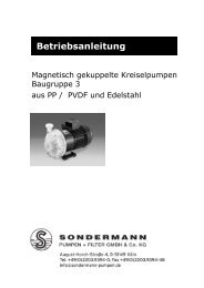
Operating Instructions<br />
EG-Konformitätserklärung<br />
EC Declaration of <strong>Co</strong>nformity<br />
Déclaration de <strong>Co</strong>nformité CE<br />
Hiermit erklären wir, dass die <strong>SONDERMANN</strong> magnetisch gekuppelten Kreiselpumpen<br />
in den gelieferten Werkstoffen und Ausführungen, folgenden einschlägigen Bestimmungen<br />
entsprechen:<br />
We herewith confirm that the <strong>SONDERMANN</strong> magnetically coupled centrifugal pumps<br />
in the supplied materials and versions corresponds to the following EC-rules:<br />
Nous confirmons que les pompes centrifuges à accouplement magnétique<br />
<strong>SONDERMANN</strong>, livrées en matériaux et versions différents, sont conformes aux dispositions<br />
règlementaires suivantes:<br />
(1) EG-Richtlinie Maschinen EC Machinery Directive Directive CE Machines<br />
98/37/CE 98/37/CE 98/37/CE<br />
(2) EG-Niederspannungsrichtlinie EC Low Voltage Directive Directive CE Bas Voltages<br />
2006/95/EG 2006/95/EG 2006/95/EG<br />
Köln, 01.08.2007<br />
2
<strong>Co</strong>ntents<br />
CONTENTS<br />
1 General information ........................................................................................... 5<br />
1.1 Fields of application: ...................................................................................................5<br />
1.2 Technical data.............................................................................................................5<br />
2 Safety .................................................................................................................. 6<br />
2.1 Marking of safety <strong>instruction</strong>s in this operating manual ..............................................6<br />
2.2 Qualification and training of operating personnel........................................................7<br />
2.3 Hazards in the event of non-compliance with safety <strong>instruction</strong>s................................7<br />
2.4 Working in compliance with safety regulations ...........................................................7<br />
2.5 Safety <strong>instruction</strong>s relevant for operating the pump....................................................7<br />
2.6 Safety <strong>instruction</strong>s relevant for maintenance, inspection and assembly work ............8<br />
2.7 Unauthorized alterations and production of spare parts .............................................8<br />
2.8 Inadmissible modes of <strong>operation</strong> ................................................................................8<br />
3 Transportation and storage............................................................................... 8<br />
3.1 Transportation .............................................................................................................8<br />
3.2 Storage........................................................................................................................8<br />
4 Functional characteristics and accessories .................................................... 8<br />
4.1 General description .....................................................................................................8<br />
4.2 <strong>Co</strong>nstructional design..................................................................................................9<br />
5 Mounting and installation.................................................................................. 9<br />
5.1 Mounting ...................................................................................................................10<br />
5.2 Hose and pipe lines...................................................................................................10<br />
5.3 Electrical connection .................................................................................................11<br />
5.4 Check sense of rotation ............................................................................................11<br />
6 Starting and shut-down procedures............................................................... 12<br />
6.1 Preparations for starting............................................................................................12<br />
6.2 Starting the pump......................................................................................................12<br />
6.3 Operation ..................................................................................................................12<br />
6.4 Shut-down procedure................................................................................................12<br />
6.5 Waste disposal..........................................................................................................13<br />
7 Service and maintenance ................................................................................ 13<br />
7.1 General information...................................................................................................13<br />
7.2 Preventive maintenance............................................................................................13<br />
7.3 Disassembly of the pump head.................................................................................14<br />
7.4 Re-assembly of the pump .........................................................................................15
<strong>Co</strong>ntents<br />
8 Troubleshooting............................................................................................... 17<br />
9 Appendix........................................................................................................... 18<br />
9.1 Spare parts list and drawing......................................................................................18<br />
9.2 Dimensioned drawing and specifications RM pumps of type 4.................................22<br />
9.3 Dimensioned drawing and specifications RM pumps of type 4.5..............................24<br />
9.4 Labour protection and accident prevention ...............................................................26<br />
9.5 Declaration of harmlessness.....................................................................................27<br />
4
Operating Instructions<br />
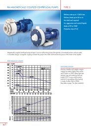
1 General information<br />
The pump may only be used in the range<br />
of applications authorized by the<br />
manufacturer. In case of modified<br />
operating conditions, please consult your<br />
pump's supplier and / or the manufacturer.<br />
1.1 Fields of application:<br />
• Pumping low-viscosity liquids<br />
resembling water.<br />
• Pumping of acids, bases and others.<br />
• Pumping of gaseous fluids.<br />
• Any use other than the authorized one<br />
as well as any conversion of the pump<br />
is not permitted.<br />
CAUTION!<br />
Make sure that the materials of which<br />
the pump is made, are resistant to the<br />
fluids delivered.<br />
Ask your pump's supplier or the<br />
manufacturer for the respective<br />
chemical resistance list.<br />
• If you deliver crystallising fluids, make<br />
sure that the fluid does not crystallise<br />
within the pump. Should this happen,<br />
carefully rinse off all parts being in<br />
contact with the fluid once the pump<br />
has been shut off.<br />
NOTE<br />
Disassembly of the pump will cancel<br />
the right to all warranty claims!<br />
1.2 Power ratings<br />
The nameplate on the pump not only<br />
specifies its model type but also its<br />
operating data and serial number. Please<br />
indicate all these data when inquiring<br />
about an issue, reordering parts and<br />
especially when ordering spare parts. For<br />
further information, contact your pump's<br />
supplier or the manufacturer.<br />
1.2 Technical data<br />
(See also Appendix)<br />
Max. volume flow see the nameplate<br />
Max. delivery head see the nameplate<br />
PP, PVDF, stainless steel,<br />
Made of<br />
ceramics, FKM, EPDM, or<br />
FEP<br />
Supply voltage see the nameplate<br />
Motor capacity 0,75 up to 7,5 kW<br />
Current rating: A see the nameplate<br />
clockwise, seen from the<br />
Sense of rotation<br />
pump towards the motor<br />
Speed<br />
2.850 rpm<br />
Protection class IP 55<br />
Max. admissible temperature of fluid delivered<br />
PP 80°C<br />
PVDF 95°C<br />
Stainless steel 100°C<br />
Maximum system pressure at 20°C<br />
PP<br />
PVDF<br />
Stainless steel<br />
NOTE<br />
5,0 bar<br />
6,0 bar<br />
10,0 bar<br />
To find out the maximum admissible<br />
temperature of the fluid delivered,<br />
check out the materials of which the<br />
pump is made and which are indicated<br />
on the nameplate or the delivery note.
Operating Instructions<br />
The letters written on the nameplate are to<br />
be read as follows:<br />
PP = glass-fibre reinforced<br />
polypropylene<br />
PVDF = polyvinylidene fluoride<br />
VA = stainless steel<br />
K = oxide ceramic<br />
G = PTFE graphite<br />
V = gasket*)<br />
K = ceramic sleeve bearings<br />
K = ceramic starting ring of the<br />
pump housing<br />
K = ceramic centering shaft<br />
*) materials available:<br />
V = FKM (fluorinated rubber)<br />
E = EPDM (ethylene-propylene<br />
terpolymer)<br />
T = FEP (fluorinated ethylene propylene)<br />
coated<br />
2 Safety<br />
When installing, operating and maintaining<br />
the pump, the mounting and operating<br />
<strong>instruction</strong>s detailed in the following<br />
should be strictly observed. Hence it is<br />
absolutely necessary that prior to<br />
assembling and starting the pump, the<br />
responsible installation personnel and/or<br />
users carefully read these operating<br />
<strong>instruction</strong>s. Make sure that they are<br />
always available wherever the pump is<br />
used.<br />
Not only the safety <strong>instruction</strong>s detailed in<br />
this Safety chapter are to be observed but<br />
also the specific safety <strong>instruction</strong>s<br />
provided in the following chapters.<br />
safety sign<br />
acc. to German DIN 4844-W9 standard.<br />
Warnings of electricity are identified by the<br />
specific<br />
safety sign<br />
acc. to German DIN 4844-W standard.<br />
Safety <strong>instruction</strong>s non-compliance with<br />
which would give rise to malfunctions of<br />
the equipment are identified by<br />
.<br />
CAUTION!<br />
Signs and labels affixed to the equipment<br />
such as<br />
• arrows indicating the sense of rotation,<br />
• symbols indicating fluid connections,<br />
• warnings to protect the pump from dryrunning,<br />
must be strictly observed and always kept<br />
legible.<br />
2.1 Marking of safety <strong>instruction</strong>s<br />
in this operating manual<br />
Safety <strong>instruction</strong>s given in this manual<br />
and non-compliance with which could be<br />
injurious to human beings, are identified<br />
by the general<br />
6
Operating Instructions<br />
2.2 Qualification and training of<br />
operating personnel<br />
All personnel responsible for <strong>operation</strong>,<br />
maintenance, inspection and assembly of<br />
the pump must be adequately qualified.<br />
Scope of responsibility and supervision of<br />
the personnel must be exactly defined by<br />
the plant operator. If staff members do not<br />
have the necessary knowledge, they<br />
should be trained and instructed<br />
accordingly. If necessary, the pump<br />
manufacturer or supplier will hold this<br />
training on behalf of the plant operator.<br />
The operator should also make sure that<br />
all operating <strong>instruction</strong>s are fully<br />
understood by all personnel.<br />
2.3 Hazards in the event of noncompliance<br />
with safety<br />
<strong>instruction</strong>s<br />
Non-compliance with safety <strong>instruction</strong>s<br />
may produce a risk to personal life and<br />
health as well as to the environment and<br />
the pump and may result in a loss of any<br />
right to claim damages.<br />
Non-compliance may involve risks such as<br />
• failure of important functions of the<br />
pump and/or the installation;<br />
• failure of specified procedures of<br />
service and maintenance;<br />
2.4 Working in compliance with<br />
safety regulations<br />
When operating the pump, make sure to<br />
observe the safety <strong>instruction</strong>s contained<br />
in this manual as well as the relevant<br />
national accident prevention regulations<br />
and any other service and safety<br />
<strong>instruction</strong>s issued by the plant operator.<br />
2.5 Safety <strong>instruction</strong>s relevant for<br />
operating the pump<br />
• If hot or cold machine components<br />
create any risk, they must be guarded<br />
against accidental contact.<br />
• Guards for moving parts must not be<br />
removed from the equipment during<br />
<strong>operation</strong>.<br />
• Hazardous (i. e. toxic, hot) fluids must<br />
be drained off to prevent any risk to<br />
persons or the environment. Statutory<br />
regulations are to be complied with in<br />
any case.<br />
• Any hazard resulting from electricity<br />
should be ruled out completely. (For<br />
details see the German VDE<br />
specifications and the bye-laws of your<br />
local power supply utilities, for<br />
example.)<br />
• exposure of persons to electrical,<br />
mechanical, magnetic and chemical<br />
hazards;<br />
• endangering of the environment<br />
because of hazardous substances<br />
leaking.
Operating Instructions<br />
2.6 Safety <strong>instruction</strong>s relevant for<br />
maintenance, inspection and<br />
assembly work<br />
It shall be the plant operator´s<br />
responsibility to ensure that all<br />
maintenance, inspection and assembly<br />
work is performed by authorized and<br />
qualified personnel who have adequately<br />
familiarized themselves with the subject<br />
matter by studying this manual in detail.<br />
Any work on the equipment shall only be<br />
performed when it is at a standstill. Make<br />
sure to strictly follow the procedure for<br />
shutting down the equipment prescribed in<br />
this manual.<br />
Pumps and pump units that deliver<br />
hazardous fluids must be decontaminated<br />
after use.<br />
On completion of work all safety and<br />
protective guards must be re-installed and<br />
be fully <strong>operation</strong>al again.<br />
Prior to restarting the pump, make sure to<br />
follow the <strong>instruction</strong>s detailed in the<br />
Starting chapter below.<br />
2.7 Unauthorized alterations and<br />
production of spare parts<br />
The user is not allowed to subject the<br />
pump to any modification unless agreed<br />
upon with the manufacturer. It is in the<br />
interest of your safety to use genuine<br />
spare parts and accessories authorized by<br />
the manufacturer. Use of other parts may<br />
exempt the manufacturer from any liability<br />
resulting thereof.<br />
2.8 Inadmissible modes of<br />
<strong>operation</strong><br />
Operational reliability of this equipment is<br />
only guaranteed if it is used in the manner<br />
intended, i.e. in accordance with chapter<br />
1, General information, of this manual. The<br />
limit values specified in the data sheet<br />
must not be exceeded under any<br />
circumstances.<br />
3 Transportation and storage<br />
3.1 Transportation<br />
The pump leaves the manufacturer's<br />
production site in a ready-to-work state. In<br />
the event of damages occurring during<br />
and due to transportation, the forwarding<br />
agent has to make a factual statement.<br />
The equipment should always be<br />
transported according to good professional<br />
practice.<br />
3.2 Storage<br />
The pump has to be stored absolutely dry<br />
and be protected from any pollutants<br />
entering.<br />
4 Functional characteristics<br />
and accessories<br />
4.1 General description<br />
Magnetically coupled centrifugal pumps of<br />
type RM are non-self-priming centrifugal<br />
pumps. They operate in horizontal position<br />
and are made of plastic in monobloc<br />
design. A magnetic coupling connects the<br />
pump to the motor and transmits the<br />
power of the motor to the impeller.<br />
8
Operating Instructions<br />
4.2 <strong>Co</strong>nstructional design<br />
Housing, impeller, impeller magnet and<br />
rear casing are made of plastic. Standard<br />
pumps are equipped with centering shafts<br />
and bearings made of oxide ceramic. The<br />
rear casing hermetically seals the fluid<br />
from the ambient atmosphere. Because of<br />
magnetic power transmission, there is no<br />
need to mechanically seal the shaft. So, in<br />
contrast to mechanically or gland sealed<br />
pumps, leakages through worn shaft<br />
sealings are definitely ruled out.<br />
Choice of materials:<br />
depends of type, see nameplate<br />
Pump housing and<br />
rear casing, impeller<br />
and impeller magnet<br />
coating<br />
Centering shaft<br />
Sleeve bearings<br />
Starting rings<br />
Static O-ring seals<br />
PP, PVDF or<br />
stainless steel<br />
oxide ceramic<br />
oxide ceramic<br />
PTFE graphite<br />
oxide ceramic<br />
FKM, EPDM, FEP<br />
(FKM and FEP<br />
coated)<br />
4.3 Accessories and optional<br />
equipment<br />
This pump is magnetically coupled. So<br />
when handling permanent-magnet<br />
components during repair or<br />
maintenance work you are exposed to<br />
magnetic forces which might influence<br />
pacemakers, for example.<br />
Keep your distance.<br />
The pump housing parts are sealed by<br />
static O-rings. The impeller of the pump is<br />
a radial-flow wheel. Depending on the fluid<br />
delivered, each component of the pump is<br />
available in various materials.<br />
NOTE<br />
The materials used for the pump are<br />
specified on its nameplate or the<br />
delivery note.<br />
Accessory components including hose<br />
connections, pilotherms, motor circuitbreakers<br />
and flow monitors, are available<br />
on request.<br />
5 Mounting and installation<br />
The pump should be installed at a place<br />
that allows easy access at any time. Make<br />
sure to keep to the following limit values:<br />
Ambient temperature<br />
Humidity of the air<br />
NOTE<br />
-10°C to +40°C<br />
max. 95% relative<br />
humidity, noncondensing<br />
In case of higher ambient temperatures,<br />
please contact your pump's supplier or<br />
the manufacturer.
Operating Instructions<br />
5.1 Mounting<br />
The pump is usually mounted in horizontal<br />
position, vertical position only upon<br />
request.<br />
This pump is not self-priming and<br />
therefore requires a feed line.<br />
• For easy installation and removal of the<br />
pump, a shut-off valve (but no<br />
diaphragm valve) should be built into<br />
the suction line.<br />
CAUTION!<br />
Do not use the shut-off valve built into<br />
the suction line to adjust the delivery<br />
rate.<br />
5.2.2 Discharge line<br />
5.2 Hose and pipe lines<br />
Make sure that the cross-sections of the<br />
pipelines fit the suction and discharge<br />
ports. All suction and discharge lines to<br />
the pump housing should be free of tensile<br />
stress. The weight of the hose and pipe<br />
lines must not rest on the housing.<br />
• Standard flow velocity within the<br />
discharge line is 3m/s.<br />
• To adjust the flow rate, we recommend<br />
installing a control element to the<br />
discharge line.<br />
CAUTION!<br />
Do not install any quick-acting stop<br />
valves into the pipelines, since<br />
pressure jerks will damage the pump<br />
housing.<br />
5.2.1 Suction line<br />
• The suction line should be a tube or<br />
hose which will not deform by the<br />
resulting partial vacuum or by high<br />
temperatures.<br />
• The suction line should be as short as<br />
possible. Make sure to mount it so that<br />
there will be no gas accumulation.<br />
• When dimensioning pipelines, fittings<br />
etc., make sure to keep the flow<br />
resistances as low as possible.<br />
• Flow velocity within the fitted suction<br />
line should not exceed the limit of 1m/s.<br />
10
Operating Instructions<br />
5.3 Electrical connection<br />
• Check out whether the power supply<br />
available corresponds to the data given<br />
on the nameplate.<br />
• The motor must be equipped with a<br />
motor circuit-breaker or a pilotherm to<br />
protect it from overloading.<br />
All electrical connections to the pump<br />
should be performed by experts only.<br />
• All electrical connections and<br />
installations of additional protection<br />
devices should be performed by<br />
experts only and in accordance with the<br />
<strong>instruction</strong>s of your local power supplier<br />
and/or the Association of German<br />
Electrotechnical Engineers VDE.<br />
• Make sure that the power supply has<br />
been cut off for at least 5 minutes<br />
before you start working on the terminal<br />
box of the pump.<br />
The electrical connections had to be done<br />
according to the following schematic<br />
Three phase motor:<br />
NOTE<br />
Motor protection devices are<br />
available with the pump's<br />
manufacturer.<br />
5.4 Check sense of rotation<br />
CAUTION!<br />
Do not check the sense of rotation<br />
before the pump is filled with fluid.<br />
• Fill the pump housing and the suction<br />
line with water or the fluid to be<br />
delivered.<br />
• Check the sense of rotation of the<br />
motor by switching it on and off in<br />
immediate succession. The sense of<br />
rotation must be in accordance with the<br />
arrow figuring on the pump.<br />
Slip a soft material, such as a paper<br />
strip, into the slits of the motor skirt to<br />
determine the sense of rotation<br />
• Mind the sense of rotation indicated by<br />
an arrow on the pump and verify it after<br />
installation.
Operating Instructions<br />
6 Starting and shut-down<br />
procedures<br />
6.1 Preparations for starting<br />
Always wear protective clothing.<br />
• Fill the pump housing and the suction<br />
line with water or the fluid to be<br />
delivered.<br />
CAUTION!<br />
Avoid any dry-running of the pump!<br />
NOTE<br />
We recommend installing dry-running<br />
protection devices such as flow<br />
monitors, contact manometers,<br />
differential pressure switches or level<br />
controllers.<br />
• Tighten all screwed connections.<br />
• Entirely open all valves of the suction<br />
line.<br />
6.2 Starting the pump<br />
• Switch on the motor.<br />
• Check the sense of rotation.<br />
• Adjust the operating point by slowly<br />
opening the shut-off valve of the<br />
discharge line. If there is no shut-off<br />
valve installed to the discharge line, the<br />
operating point is automatically<br />
adjusted in accordance with the<br />
characteristic curve of the pump.<br />
CAUTION!<br />
Do not run the pump with the discharge<br />
line closed for a longer period of time.<br />
This may result in heating up the fluid<br />
inside the pump housing and damaging<br />
interior components of the pump.<br />
CAUTION!<br />
Always protect the pump from coarse<br />
impurities and magnetisable metal<br />
particles within the fluid delivered.<br />
6.3 Operation<br />
If the motor-círcuit breaker switched off the<br />
pump motor, proceed as follows:<br />
• Before switching on the motor again,<br />
check whether the impeller turns<br />
readily.<br />
• Make sure that the suction line and the<br />
pump housing are filled with fluid.<br />
• Switch on the motor.<br />
If the pump delivers for a short period of<br />
time only and then stops pumping, the<br />
magnetic coupling has been disengaged.<br />
Proceed as described in chapter 8,<br />
Troubleshooting, below.<br />
6.4 Shut-down procedure<br />
• Switch off the motor.<br />
• Close all valves.<br />
• In case some fluid remains within the<br />
pump, secure the shut-off valves to<br />
prevent an accidental opening.<br />
• If the pump is not to be used for some<br />
time, carefully rinse it off with a clean<br />
and neutral liquid. This is to prevent<br />
remaining fluid from depositing within<br />
the pump and the sleeve bearings.<br />
• If the pump is shut down for repair or<br />
maintenance work, lock the driving unit<br />
so that it cannot be switched on. Before<br />
dismantling the pump, close the suction<br />
and the discharge lines and empty the<br />
pump under controlled conditions.<br />
Secure all valves to prevent an<br />
accidental opening.<br />
Wear protective clothing.<br />
12
Operating Instructions<br />
6.5 Waste disposal<br />
This product as a whole as well as parts of<br />
it should be disposed of in an<br />
environmentally safe way.<br />
CAUTION!<br />
Please comply with the respective<br />
regulations that are currently in force at<br />
your place (especially with regard to<br />
electronic scrap).<br />
• If dirty, silty or crystallising fluids are<br />
delivered, the pump should be<br />
inspected more often and cleaned, if<br />
necessary.Check the static sealings in<br />
regular intervals and replace them, if<br />
necessary.<br />
CAUTION!<br />
When assembling or disassembling the<br />
pump, make sure that there are no<br />
magnetisable metal particles in the<br />
working area.<br />
7 Service and maintenance<br />
7.1 General information<br />
This pump is designed for continuous<br />
<strong>operation</strong> and does not require specific<br />
maintenance.<br />
7.2 Preventive maintenance<br />
• Although bearings, centering shaft and<br />
starting rings are designed for<br />
continuous <strong>operation</strong>, they should be<br />
periodically inspected for deposits.<br />
CAUTION!<br />
Make sure that the materials of which<br />
the pump is made, are resistant to the<br />
fluids delivered.<br />
• If you deliver crystallising fluids, make<br />
sure that the fluid does not crystallise<br />
within the pump. Should this happen,<br />
carefully rinse off all parts being in<br />
contact with the fluid once the pump<br />
has been shut off.<br />
When the complete head of the pump is<br />
assembled or disassembled, magnetic<br />
forces can cause serious injury.<br />
• If not only wear parts are replaced, but<br />
also repair work is to be done, this<br />
should be performed by an expert only.<br />
Inappropriate service and maintenance<br />
work often results in a waste of money.<br />
Please indicate all these data when<br />
inquiring about an issue, reordering<br />
parts and especially when ordering<br />
spare parts. For further information,<br />
contact your pump's supplier or the<br />
manufacturer.<br />
NOTE<br />
Disassembly of the pump will cancel<br />
the right to all warranty claims!<br />
• The nameplate on the pump not only<br />
specifies its model type but also its<br />
operating data and serial number.
Operating Instructions<br />
7.3 Disassembly of the pump head<br />
1. Loosen the 6 srews (901.1) of the pump<br />
housing. (101)<br />
Required tool: open-end or ring<br />
spanner of size 10<br />
2. Take the pump head (001) from lantern<br />
(113).<br />
No tools required.<br />
3. Take the pump housing (101) off the rear<br />
casing (161). Pull the impeller with the<br />
inner magnet (230 +847.1) and the<br />
centering shaft (211) out of the housing<br />
No tools required.<br />
4. Remove the bearings (310) by forcing<br />
them backwards out of the impeller magnet<br />
(847.1).<br />
Required tool: hand lever press + 20 mm<br />
pin.<br />
14
Operating Instructions<br />
5. Remove the impeller (230) from the<br />
impeller magnet (847.1).<br />
Required tool: tire lever<br />
6. Take the thrust ring (314.2) off the impeller<br />
(230).<br />
Required tool: tbular piece Ø inside<br />
80 mm, driftpin Ø 6mm!<br />
7.4 Re-assembly of the pump<br />
7. Assemble the bearings (310) and (310.2). 8. Press the impeller (230) onto the impeller<br />
magnet (847.1).<br />
Required tool: hand lever press Required tool: hand lever press +<br />
plastic pressure disk<br />
Ø80mm!
Operating Instructions<br />
To assemble the pump head reverse steps 1 to 6 described above.<br />
.<br />
CAUTION!<br />
Once the complete head of the pump has been assembled, the impeller (230) and the<br />
impeller magnet (847.1) should be sliding along the axis of the centering shaft (211).<br />
16
Operating Instructions<br />
8 Troubleshooting<br />
Malfunction Causes <strong>Co</strong>rrective action<br />
Pump does not work when<br />
switched on<br />
Magnetic clutch is<br />
disengaged<br />
Motor is overheating<br />
No voltage<br />
Impurities in the pump<br />
housing<br />
Specific gravity and/or<br />
viscosity of the fluid is too<br />
high<br />
Pump was switched off, then<br />
switched on again before the<br />
rotor stopped<br />
Clogged ventilator cowl<br />
Test the voltage<br />
Remove the impurities<br />
Reduce the delivery rate; use<br />
a stronger magnetic clutch<br />
and a more powerful motor<br />
The rotor should have<br />
stopped before the pump can<br />
be switched on again<br />
Clean the ventilator and the<br />
cowl<br />
Pump is working, but not<br />
delivering<br />
Motor is overloaded<br />
Gas accumulation in the lines<br />
Reduce the delivery rate<br />
Use a stronger motor<br />
Evacuate the lines<br />
Valve in suction / delivery line Open the valves<br />
is closed<br />
Too much flow noise Cavitation Increase the suction line<br />
cross-section<br />
Reduce the delivery rate<br />
cool down the fluid<br />
Pump is not sucking No fluid in the pump Open the vane<br />
Delivery rate too low<br />
Delivery rate too high<br />
Air in the system<br />
Suction and delivery line<br />
cross-sections are too small<br />
(significant losses)<br />
Valve is not entirely open<br />
Pump losses are less<br />
significant than presumed<br />
Evacuate the system<br />
Increase the suction and<br />
delivery line cross-sections<br />
Entirely open the valve<br />
Install a flow control valve in<br />
the delivery line<br />
17
Operating Instructions<br />
9 Appendix<br />
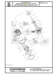
9.1 Spare parts list and drawing<br />
Spare part drawing -- coupling length 60 mm<br />
Drawing no. PUMA.04.Z.395.001<br />
18
Operating Instructions<br />
Spare part list – coupling length 60 mm<br />
19
Operating Instructions<br />
Spare part drawing -- coupling length 90 mm<br />
Drawing no. PUMA.04.Z.396.001<br />
20
Operating Instructions<br />
Spare part list – coupling length 90 mm<br />
21
Operating Instructions<br />
9.2 Dimensioned drawing and specifications RM pumps of type 4<br />
22
Operating Instructions<br />
Measured with water at a temperature of 20°C.<br />
23
Operating Instructions<br />
9.3 Dimensioned drawing and specifications RM pumps of type 4.5<br />
24
Operating Instructions<br />
Measured with water at a temperature of 20°C.<br />
25
Operating Instructions<br />
9.4 Labour protection and accident prevention<br />
NOTE<br />
In order to protect their employees and other people as well as the environment from harmful<br />
influences and effects when handling hazardous substances, industrial and commercial<br />
companies are obliged to comply with legal provisions referring to labour protection such as the<br />
German Workplace Regulations (ArbStättV), Hazardous Substances Regulations (GefStoffV)<br />
and regulations for the prevention of accidents, as well as environmental regulations such as<br />
the German Waste Act (AbfG) and the Water Resources Law (WHG).<br />
We therefore ask you to enclose a declaration of harmlessness with any pump or component<br />
you send us for repair. With this form duly filled in and signed, you declare that the pump or the<br />
component was cleaned and thorougly rinsed with neutral fluid before being shipped to us.<br />
Notwithstanding this, we reserve the right to refuse acceptance of repair orders for any other<br />
reason.<br />
So <strong>SONDERMANN</strong> products and their components are neither serviced nor repaired unless this<br />
declaration of harmlessness is enclosed (see page 25 below).<br />
Pumps that have been operated with radioactive substances are not accepted at all.<br />
In case that, although the pump was carefully emptied and cleaned, we have to take any safety<br />
precautions, you have to give us the necessary information when sending the pump or its<br />
component.<br />
26
Operating Instructions<br />
9.5 Declaration of harmlessness<br />
The undersigned herewith declares that the following pump and its accessories are harmless<br />
and asks you to service and/or repair it or them.<br />
Type of the pump:<br />
...................................................................................................................<br />
...................................................................................................................<br />
Serial number:<br />
...................................................<br />
Date of delivery:<br />
...................................................<br />
Kind of problem:<br />
We herewith declare that<br />
...................................................................................................................<br />
...................................................................................................................<br />
the pump was not used to deliver harmful or noxious substances;<br />
□<br />
it was used with the following fluids:<br />
..................................................................................................................................<br />
..................................................................................................................................<br />
□<br />
□<br />
□<br />
before being shipped, the pump was carefully emptied and cleaned inside and<br />
out;<br />
it is not necessary to take any special safety precautions;<br />
you have to take the following safety precautions with regard to residual fluids and<br />
waste disposal:<br />
...................................................................................................................................<br />
...................................................................................................................................<br />
Date:<br />
signature:<br />
27
Operating Instructions<br />
S O N D E R M A N N<br />
PUMPEN + FILTER GMBH & <strong>Co</strong>. KG<br />
August-Horch-Str.4<br />
D - 51149 Köln (<strong>Co</strong>logne - Germany)<br />
Tel.: +49 (0) 2203/9394-0<br />
Fax: +49 (0) 2203/9394-48<br />
info@sondermann-pumpen.de<br />
www.sondermann-pumpen.de<br />
<strong>Co</strong>pyright by <strong>SONDERMANN</strong> PUMPEN + FILTER GMBH & <strong>Co</strong>. KG • Technische Änderungen vorbehalten • SB BG4; 4.5 -E-Jan-2008<br />
Subject to technical modification<br />
28