Service Source Power Mac G5 - Retrocomputing.net
Service Source Power Mac G5 - Retrocomputing.net
Service Source Power Mac G5 - Retrocomputing.net

Create successful ePaper yourself
Turn your PDF publications into a flip-book with our unique Google optimized e-Paper software.
apple <strong>Service</strong> <strong>Source</strong><br />
<strong>Power</strong> <strong>Mac</strong> <strong>G5</strong><br />
Updated: 24 September 2003<br />
© 2003 Apple Computer, Inc. All rights reserved.
apple <strong>Service</strong> <strong>Source</strong><br />
Basics<br />
<strong>Power</strong> <strong>Mac</strong> <strong>G5</strong><br />
© 2003 Apple Computer, Inc. All rights reserved.
Overview<br />
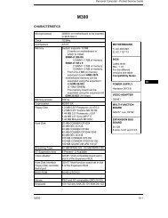
<strong>Power</strong> <strong>Mac</strong> <strong>G5</strong> is a 64-bit desktop computer powered by the <strong>Power</strong>PC <strong>G5</strong> processor. It<br />
offers memory expansion up to 8GB,1 GHz front-side bus, and advanced 64-bit<br />
computation, while running existing 32-bit applications natively. The computer also<br />
includes serial ATA hard drives, high-end graphics capabilities, and computer-controlled<br />
cooling based on four independent zones. Standard configurations are listed below.<br />
1.6 GHz Uni 1.8 GHz Uni 2 GHz Dual<br />
800 MHz frontside bus 900 MHz frontside bus 1 GHz frontside bus<br />
256 MB DDR333 SDRAM,<br />
expandable to 4 GB<br />
512 MB DDR400 SDRAM,<br />
expandable to 8 GB<br />
512 MB DDR400 SDRAM,<br />
expandable to 8 GB<br />
80 GB Serial ATA drive 160 GB Serial ATA drive 160 GB Serial ATA drive<br />
SuperDrive SuperDrive SuperDrive<br />
Three PCI slots Three PCI-X slots Three PCI-X slots<br />
NVIDIA GeForce FX 5200<br />
Ultra video card<br />
NVIDIA GeForce FX 5200<br />
Ultra video card<br />
ATI Radeon 9600 Pro<br />
video card<br />
56K internal modem 56K internal modem 56K internal modem<br />
Overview<br />
<strong>Power</strong> <strong>Mac</strong> <strong>G5</strong> Basics - 1
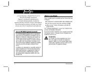
Serial Number Location<br />
To identify a particular model of <strong>Power</strong> <strong>Mac</strong> <strong>G5</strong>, check the computer’s serial number,<br />
which lists the model’s configuration. The serial number is located directly below the air<br />
deflector inside the side access panel.<br />
2 - <strong>Power</strong> <strong>Mac</strong> <strong>G5</strong> Basics Serial Number Location
What’s New<br />
Overview<br />
<strong>Power</strong>PC <strong>G5</strong>— The <strong>Power</strong> <strong>Mac</strong> <strong>G5</strong> computer incudes the new 64-bit <strong>Power</strong>PC <strong>G5</strong><br />
processor running at either 1.6, 1.8, or 2.0 GHz, well beyond the speeds of G4 processors.<br />
Serial ATA hard drives — Unlike older parallel drives, the new serial ATA drives in the<br />
<strong>Power</strong> <strong>Mac</strong> <strong>G5</strong> offer up to 150 MB/s data throughput. The 7200 rpm drives come in 80,<br />
160, or 250 GB capacity.<br />
PCI-X slots—Higher-bandwidth PCI slots allow for greater amounts of data when using<br />
expansion cards that demand high performance. Both 100 and 133 MHz PCI-X slots are<br />
included in higher-end <strong>Power</strong> <strong>Mac</strong> <strong>G5</strong> computers. For more information, see the “AGP/PCI<br />
Card” topic in the Take Apart chapter.<br />
8x AGP bus— This bus provides a higher amount of data transfer to and from the<br />
graphics card. Both NVIDIA and ATI graphics cards are offered for the <strong>Power</strong> <strong>Mac</strong> <strong>G5</strong>.<br />
USB 2.0 —All USB ports on the <strong>Power</strong> <strong>Mac</strong> <strong>G5</strong> support the USB 2.0 standard, which<br />
accommodates more high speed peripherals.<br />
Digital audio in and out —The <strong>Power</strong> <strong>Mac</strong> <strong>G5</strong> introduces two new optical audio (S/PDIF)<br />
ports, allowing for optical audio input and output. These ports are in addition to the existing<br />
analog sound input and output ports.<br />
Cooling zones — Nine case fans and blowers are logically grouped into four separate<br />
cooling zones in the <strong>Power</strong> <strong>Mac</strong> <strong>G5</strong>. Each zone is software-controlled by the system to<br />
only cool when necessary, making for a more efficient (and quieter) cooling solution.<br />
Controller chips— The <strong>Power</strong> <strong>Mac</strong> <strong>G5</strong> includes Northbridge and Southbridge controller<br />
chips that use “hyper-transport” technology. This new technology allows chips to talk to<br />
each other much faster than older <strong>Mac</strong>s. The overall bandwidth of the system is also<br />
greatly improved.<br />
ATA/100 bus for optical drives— This technology allows optical storage to read/write<br />
data much faster.<br />
Interleaved DDR RAM—The <strong>Power</strong> <strong>Mac</strong> <strong>G5</strong> requires pairs of DIMMs, which increases<br />
performance. Different models require either DDR 333 or DDR 400 RAM. DIMMs must be<br />
installed in pairs of equal size and kind. For more information, see the “Memory (DIMMs)”<br />
topic in the Take Apart chapter.<br />
What’s New<br />
<strong>Power</strong> <strong>Mac</strong> <strong>G5</strong> Basics - 3
DDR Memory<br />
Depending on the model, <strong>Power</strong> <strong>Mac</strong> <strong>G5</strong> computers have either four or eight Dual Inline<br />
Memory Module (DIMM) slots for Double-Data-Rate (DDR) Synchronous Dynamic<br />
Random-Access Memory (SDRAM) devices. The computers ship with a minimum of 256<br />
MB of RAM, installed as a pair of 128 MB DIMMs in two of the DIMM slots. You can install<br />
additional DIMMs, provided they are installed in pairs of equal size. A diagram marked on<br />
the logic board near the slots illustrates how the pairs must be installed.<br />
To determine the types of DIMMs to install, refer to the table below:<br />
DIMM Slots DIMM speed Maximum amount<br />
4 (two banks of 2 slots) 333 MHz, PC 2700 up to 4 GB<br />
8 (two banks of 4 slots) 400 MHz, PC 3200 up to 8 GB<br />
In addition, DIMMs must fit these specifications:<br />
• 2.5 volt<br />
• 184-pin module<br />
• Maximum number of memory devices on DDR SDRAM:16<br />
• Nonparity<br />
• No error correcting codes (ECC)<br />
• Unbuffered (registered or buffered DDR SDRAM cannot be used)<br />
4 - <strong>Power</strong> <strong>Mac</strong> <strong>G5</strong> Basics What’s New
Video<br />
The <strong>Power</strong> <strong>Mac</strong> <strong>G5</strong> computer comes with a graphics card installed in the AGP 3.0-<br />
compliant 8x Pro slot.<br />
All graphics cards support dual displays in either extended desktop or video mirroring<br />
mode, and support digital resolutions up to 1920x1200 pixels and analog resolutions up to<br />
1600x1200 pixels.<br />
The display memory on the AGP card is separate from the main memory. The display<br />
memory consists of 64 or 128 MB of DDR devices configured to make a 128-bit data bus.<br />
The display memory cannot be expanded by the user.<br />
The supported graphics cards are shown below:<br />
Graphics Video SDRAM Connectors<br />
NVIDIA GeForce FX 5200 Ultra 64 MB DDR ADC and DVI-I<br />
ATI Radeon 9600 Pro 64 MB DDR ADC and DVI-I<br />
ATI Radeon 9800 Pro (CTO) 128 MB DDR ADC and DVI-I<br />
Fan Controller<br />
The <strong>Power</strong> <strong>Mac</strong> <strong>G5</strong> system employs advanced thermal management to keep acoustic<br />
noise to a minimum. The system is divided into discrete zones, each with independently<br />
controlled fans bringing in cool air from the front of the enclosure, directing it through ducts<br />
and exhausting it out the rear. Temperature and power consumption are monitored by the<br />
operating system, which communicates with the Fan Control Unit, which in turn controls<br />
and monitors fan operation. Note that if <strong>Mac</strong> OS X is not booted, thermal management will<br />
not work correctly.<br />
Important: To ensure proper fan and temperature control, you must run Apple <strong>Service</strong><br />
Diagnostic whenever you replace a processor or logic board with a new processor or logic<br />
board. You must also run the diagnostic if you re-install the same processor but in a<br />
different connector from the one in which it was originally installed. For more information,<br />
see “Thermal Calibration” in the Troubleshooting chapter.<br />
Optical Audio<br />
Digital data is transmitted to and from the optical audio I/O using special optical cables.<br />
The 7.5 mm digital optical connectors on the cables, commonly referred to as TOSLink,<br />
are for both input and output and conform to the IEC60874-17 connector standard.<br />
The TOSLink friction-lock type F-05 connectors are available from pro-audio, musician’s<br />
supply, hi-fi, and other retailers.<br />
What’s New<br />
<strong>Power</strong> <strong>Mac</strong> <strong>G5</strong> Basics - 5
Analog audio signals are converted to digital data internally. All audio is handled digitally<br />
inside the computer, including audio data from the CD or DVD drive and from devices<br />
connected to the USB and FireWire ports. Audio data is converted to analog form for<br />
output to the internal speaker, the headphones, or the analog output port.<br />
Wireless<br />
The <strong>Power</strong> <strong>Mac</strong> <strong>G5</strong> supports an optional internal Apple Bluetooth module that enables<br />
short-range wireless connections between desktop and laptop computers and a host of<br />
other peripheral devices. Bluetooth support is built into <strong>Mac</strong> OS X and compliant with<br />
Bluetooth specification v1.1. It operates on a globally available 2.4 GHz frequency band<br />
(ISM band) for worldwide compatibility and has a maximum throughput of 1Mbps.<br />
The Bluetooth technology supports the following profiles:<br />
• synchronization —enables synchronization of devices over Bluetooth<br />
• serial —provides a wireless serial connection to other Bluetooth devices<br />
• dial-up <strong>net</strong>working (DUN) — enables a mobile phone to act as a modem<br />
• object push —enables the transfer of files between Bluetooth devices<br />
Important: For proper range and operation, the external Bluetooth antenna must be<br />
attached to the Bluetooth port and the external AirPort antenna must be attached to the<br />
AirPort port on the back panel of the <strong>Power</strong> <strong>Mac</strong> <strong>G5</strong>.<br />
Ports<br />
The following ports are included on the front and back panels of the <strong>Power</strong> <strong>Mac</strong> <strong>G5</strong>. For<br />
illustrations of the port locations, see the “External Views” topic in the Views chapter.<br />
Front<br />
• <strong>Power</strong> button<br />
• Headphone port<br />
• USB 2.0 port<br />
• FireWire 400 port<br />
Rear<br />
• AirPort antenna port<br />
• Bluetooth antenna port<br />
• Optical audio-out port<br />
• Optical audio-in port<br />
• Audio line-out port<br />
• Audio line-in port<br />
• USB 2.0 ports (two ports)<br />
• FireWire 400 port<br />
• FireWire 800 port<br />
• 10/100/1000Base-T Ether<strong>net</strong> port<br />
• Modem port<br />
6 - <strong>Power</strong> <strong>Mac</strong> <strong>G5</strong> Basics What’s New
apple <strong>Service</strong> <strong>Source</strong><br />
Take Apart<br />
<strong>Power</strong> <strong>Mac</strong> <strong>G5</strong><br />
© 2003 Apple Computer, Inc. All rights reserved.
General Information<br />
Orientation<br />
For most take-apart procedures, it is recommended that you lay the computer on its side<br />
before removing or installing the part. For proper operation, however, Apple recommends<br />
that the unit be run in the upright position. The computer should never be operated on its<br />
side with the access panel facing down.<br />
Tools<br />
The following tools are required to service the computer:<br />
• Long-handled mag<strong>net</strong>ic Phillips screwdriver (10-inch shaft)<br />
• Short-handled mag<strong>net</strong>ic Phillips screwdriver<br />
• Flatblade screwdriver<br />
• Jeweler’s flatblade screwdriver<br />
• Needlenose pliers<br />
• Long-handled hex wrench<br />
• Tape (for temporarily holding cables out of the way)<br />
• Small mirror (for seeing small boards inside the enclosure)<br />
• Soft cloth (for protect removed parts from scratches)<br />
General Information<br />
<strong>Power</strong> <strong>Mac</strong> <strong>G5</strong> Take Apart - 1
Opening the Computer<br />
Tools<br />
No tools are required for this procedure.<br />
Preliminary Steps<br />
1. Shut down the computer.<br />
Warning: Always shut down the computer before opening it to avoid damaging its<br />
internal components or the components you are installing. Do not open the computer<br />
or attempt to install items inside it while it is on.<br />
2. Wait 5 to 10 minutes to allow the computer’s internal components to cool.<br />
Warning: After you shut down the system, the internal components can be very hot.<br />
You must let the computer cool down before continuing.<br />
3. Unplug all external cables from the computer except the power cord.<br />
4. Touch the metal PCI access covers on the back of the computer to discharge any<br />
static electricity from your body.<br />
Important: Always discharge static before you touch any parts or install any<br />
components inside the computer. To avoid generating static electricity, do not walk<br />
around the room until you have finished working and closed the computer.<br />
5. Unplug the power cord.<br />
6. Put on an ESD wrist strap.<br />
2 - <strong>Power</strong> <strong>Mac</strong> <strong>G5</strong> Take Apart Opening the Computer
Procedure<br />
1. Hold the side access panel and lift the latch on the back of the computer.<br />
Warning: The edges of the access panel and the enclosure can be sharp. Be very careful<br />
when handling them.<br />
2. Remove the access panel and place it on a flat surface covered by a soft, clean cloth.<br />
Replacement Note: Make sure the latch is in the up position before replacing the access<br />
panel. If the latch is down, the access panel will not seat correctly in the enclosure.<br />
Opening the Computer<br />
<strong>Power</strong> <strong>Mac</strong> <strong>G5</strong> Take Apart - 3
3. Remove the air deflector and place it on a soft, clean cloth.<br />
Replacement Note: To replace the air deflector, insert the three tabs on the bottom edge<br />
of the deflector into the three slots in the bottom frame of the enclosure. Then swing the<br />
deflector up flush against the top frame of the enclosure.<br />
Important: Make sure you re-install the air deflector before replacing the access panel. If<br />
the air deflector is not installed, the computer will not function properly.<br />
4 - <strong>Power</strong> <strong>Mac</strong> <strong>G5</strong> Take Apart Opening the Computer
Serial ATA Hard Drive<br />
The <strong>Power</strong> <strong>Mac</strong> <strong>G5</strong> computer can accommodate two serial ATA hard drives in its internal<br />
hard drive bay. In most configurations, a single hard drive occupies the top portion of the<br />
bay. You can install one additional serial ATA hard drive to the empty slot in the bay.<br />
Important: Use the original Apple cables that came with the <strong>Power</strong> <strong>Mac</strong> <strong>G5</strong> when<br />
installing ATA hard drives.<br />
Tools<br />
The only tool required for this procedure is a Phillips screwdriver.<br />
Preliminary Steps<br />
Before you begin, open the computer.<br />
Part Location<br />
Serial ATA Hard Drive<br />
<strong>Power</strong> <strong>Mac</strong> <strong>G5</strong> Take Apart - 5
Procedure<br />
1. Release the drive locking latch by rotating it up.<br />
2. Disconnect the drive data cable and power cable from the hard drive.<br />
3. Pull the drive out of the drive bay, being careful not to touch the bottom of the drive.<br />
Important: If the printed circuit board (PCB) is exposed on the bottom of the hard drive,<br />
hold the drive by its sides. To avoid damaging the replacement drive, take care not to touch<br />
the PCB during installation.<br />
6 - <strong>Power</strong> <strong>Mac</strong> <strong>G5</strong> Take Apart Serial ATA Hard Drive
4. If you are replacing the drive with a new drive, transfer the four hard drive guide<br />
screws from the sides of the original drive to the replacement drive.<br />
5. If you are installing an additional drive, remove the four guide screws from the left side<br />
of the hard drive bay and screw them into the sides of the new drive.<br />
Serial ATA Hard Drive<br />
<strong>Power</strong> <strong>Mac</strong> <strong>G5</strong> Take Apart - 7
Replacement Note: When replacing the top drive, make sure the guide screws align with<br />
the middle slot of the drive bay, and then gently push the drive into the bay until it snaps<br />
into place in the top position.<br />
When installing a bottom drive, align the guide screws with the bottom slot of the drive bay<br />
and slide the drive in until it snaps into place.<br />
8 - <strong>Power</strong> <strong>Mac</strong> <strong>G5</strong> Take Apart Serial ATA Hard Drive
Optical Drive<br />
Important: When installing a replacement optical drive, use the original Apple cables that<br />
came with the <strong>Power</strong> <strong>Mac</strong> <strong>G5</strong>.<br />
Tools<br />
No tools are required for this procedure.<br />
Preliminary Steps<br />
Before you begin, open the computer.<br />
Part Location<br />
Optical Drive<br />
<strong>Power</strong> <strong>Mac</strong> <strong>G5</strong> Take Apart - 9
Procedure<br />
1. Disconnect the optical drive ribbon cable from the logic board. (The cable connector is<br />
located under the media shelf that holds the optical drive.)<br />
2. Push the optical drive levers out to release the drive.<br />
10 - <strong>Power</strong> <strong>Mac</strong> <strong>G5</strong> Take Apart Optical Drive
3. Place the fingers on one hand inside the opening for the optical drive cable and push<br />
the edge of the drive forward. The drive will move part way out of the media shelf.<br />
4. Disconnect the power cable from the drive.<br />
5. Route the drive ribbon cable out through the opening in the media shelf and remove<br />
the drive and ribbon cable from the computer.<br />
Optical Drive<br />
<strong>Power</strong> <strong>Mac</strong> <strong>G5</strong> Take Apart - 11
6. If you are replacing the drive with a new drive, install the standoffs on the bottom of the<br />
new drive.<br />
Note for SuperDrives: Two bags of standoffs are included with each drive. Use the<br />
standoffs from the bag marked with the same manufacturer’s name as printed on the<br />
drive.<br />
Note for Combo Drives: Transfer the standoffs from the original drive to the<br />
replacement drive.<br />
12 - <strong>Power</strong> <strong>Mac</strong> <strong>G5</strong> Take Apart Optical Drive
7. Disconnect the ribbon cable from the back of the drive, and then carefully pry the<br />
cable from the top of the drive. Transfer the cable to the top of the replacement drive,<br />
and connect the cable to the drive.<br />
Note: Reusable adhesive tape on the underside of the cable attaches the cable to<br />
the drive. When removing the cable from the original drive, be careful to keep the<br />
tape with the cable.<br />
8. Carefully remove the EMI shield from the front of the original drive and transfer it to the<br />
front of the replacement drive.<br />
Replacement Note: Insert the optical drive part way into the optical drive bay, and<br />
connect the power cable to the drive. Then bend down the free end of the ribbon cable,<br />
route it through the opening at the back of the media shelf, and connect the cable to the<br />
logic board.<br />
Optical Drive<br />
<strong>Power</strong> <strong>Mac</strong> <strong>G5</strong> Take Apart - 13
Front Inlet Fan(s)<br />
The front inlet fan assembly consists of one or two fans in a plastic bracket. If the computer<br />
is a uniprocessor, the assembly contains a single fan; if the computer is a dual processor,<br />
the assembly contains two fans connected by a single cable.<br />
You must remove the front inlet fan assembly to access many other parts within the<br />
computer. For this access, remove the bracket with the fans attached. You will have to<br />
remove the fans from the bracket only if you are replacing the fans themselves.<br />
Tools<br />
The only tool required for this procedure is needlenose pliers.<br />
Preliminary Steps<br />
Before you begin, open the computer and lay it on its side with the access side facing up.<br />
Part Location<br />
14 - <strong>Power</strong> <strong>Mac</strong> <strong>G5</strong> Take Apart Front Inlet Fan(s)
Procedure<br />
1. Hold the front inlet fan assembly by the front handle and firmly pull it out of the<br />
computer.<br />
Front Inlet Fan(s)<br />
<strong>Power</strong> <strong>Mac</strong> <strong>G5</strong> Take Apart - 15
2. If you are replacing the fan(s) in the bracket, do the following:<br />
• Remove the fan cable from the cable guide.<br />
• Using needlenose pliers, pull the fan(s) off the grommet fasteners, and remove the<br />
fan(s) and cable from the bracket.<br />
Important: If you are replacing two fans, be careful that you do not separate the fans<br />
from each other. They are connected by a common cable.<br />
16 - <strong>Power</strong> <strong>Mac</strong> <strong>G5</strong> Take Apart Front Inlet Fan(s)
Replacement Note: To replace the front inlet fan bracket in the enclosure, align the large<br />
rail on the bracket with the cutout in the PCI divider and press firmly.<br />
Important: Make sure the connector on the fan fully engages the fan connector on the<br />
logic board, or the computer will not operate properly. Gently pull the fan assembly to test<br />
whether it is connected.<br />
Front Inlet Fan(s)<br />
<strong>Power</strong> <strong>Mac</strong> <strong>G5</strong> Take Apart - 17
Memory (DIMMs)<br />
Depending on the model, <strong>Power</strong> <strong>Mac</strong> <strong>G5</strong> computers have either four or eight Dual Inline<br />
Memory Module (DIMM) slots arranged in two banks. The slots accept Double-Data-Rate<br />
(DDR) Synchronous Dynamic Random-Access Memory (SDRAM) devices.<br />
The computers ship with a minimum of 256 MB of RAM, provided by a pair of 128 MB<br />
DIMMs installed in slot 1 of each DIMM bank. You can add DIMMs, provided they are<br />
installed in pairs of equal size, one per bank, from the center outward. A diagram marked<br />
on the logic board near the DIMM slots illustrates how the pairs must be installed.<br />
To determine the types of DIMMs to install, refer to the table below:<br />
DIMM Slots DIMM speed Maximum amount<br />
4 333 MHz, PC 2700 up to 4 GB<br />
8 400 MHz, PC 3200 up to 8 GB<br />
18 - <strong>Power</strong> <strong>Mac</strong> <strong>G5</strong> Take Apart Memory (DIMMs)
In addition, DIMMs must fit these specifications:<br />
• 2.5 volt<br />
• 184-pin module<br />
• Maximum number of memory devices on DDR SDRAM:16.<br />
• Nonparity<br />
• No error correcting codes (ECC)<br />
• Unbuffered (registered or buffered DDR SDRAM cannot be used)<br />
Important: Always install DIMMs in pairs of equal size. Memory from older <strong>Mac</strong>intosh<br />
computers is not compatible with the <strong>Power</strong> <strong>Mac</strong> <strong>G5</strong>. Do not use older memory, even if it<br />
fits into the DIMM slots.<br />
Tools<br />
No tools are required for this procedure.<br />
Preliminary Steps<br />
Before you begin, open the computer, lay it on its side with the access side facing up, and<br />
remove the front inlet fan assembly.<br />
Part Location<br />
Memory (DIMMs)<br />
<strong>Power</strong> <strong>Mac</strong> <strong>G5</strong> Take Apart - 19
Procedure<br />
1. Locate the DIMM slots on the logic board.<br />
2. Open the ejectors on the DIMM slot by pushing them out to the sides.<br />
3. Holding the DIMM by both top corners, lift it straight up out of the computer.<br />
Replacement Note: Align the DIMM in the slot and push both ends of the DIMM down<br />
until the tabs are vertical and the ejectors snap into place.<br />
Important: Do not touch the DIMM connectors. Handle the DIMM only by the edges.<br />
20 - <strong>Power</strong> <strong>Mac</strong> <strong>G5</strong> Take Apart Memory (DIMMs)
AGP/PCI Card<br />
The <strong>Power</strong> <strong>Mac</strong> <strong>G5</strong> computer has four expansion card slots, three of which accommodate<br />
Peripheral Component Interconnect (PCI) cards and one that accepts an advanced<br />
graphics port (AGP) video card. AGP cards and PCI cards have different connectors, so<br />
you cannot insert a PCI card into the AGP slot.<br />
Note: Maximum power consumption for all four expansion slots (the three PCI expansion<br />
cards and the AGP card) should not exceed 90 watts (W).<br />
AGP Slot 1<br />
PCI Slot 2<br />
PCI Slot 3<br />
PCI Slot 4<br />
AGP Cards<br />
The AGP video card, installed in slot 1, contains the graphics processor unit (GPU) and<br />
provides the computer’s display ports. Slot 1 is designed specifically to accept AGP cards.<br />
This 533-megahertz (MHz) slot accommodates 1.5-volt (V) AGP cards.<br />
PCI Cards<br />
The remaining three expansion slots, labeled 2, 3, and 4, accommodate PCI cards up to<br />
12 inches long. Depending on the <strong>Power</strong> <strong>Mac</strong> <strong>G5</strong> model, you can install either PCI or<br />
PCI-X cards.<br />
Note: To determine if a <strong>Power</strong> <strong>Mac</strong> <strong>G5</strong> computer can accommodate PCI-X cards, check<br />
the number of DIMM slots on the logic board. Computers with four DIMM slots have<br />
AGP/PCI Card<br />
<strong>Power</strong> <strong>Mac</strong> <strong>G5</strong> Take Apart - 21
33 MHz PCI slots and cannot use PCI-X cards; computers with eight DIMM slots can<br />
accommodate 100 and 133 MHz PCI-X cards. See the chart below.<br />
Card type PCI slot Card speed<br />
PCI* slots 2, 3, and 4 64-bit, 33 MHz<br />
PCI-X slots 2 and 3 64-bit, 100 MHz<br />
slot 4<br />
64-bit, 133 MHz<br />
*The PCI slots can accommodate mixed-voltage (5.0 V, 12 V, or 3.3 V) cards but only at<br />
3.3 V signaling, with 32-bit or 64-bit data widths and a 33 MHz frequency. You can add a<br />
66 MHz card to a 33 MHz PCI slot if the card can operate at the lower 33 MHz rate.<br />
Warning: Do not use PCI cards that function only at 66 MHz in the PCI slots. Damage to<br />
the equipment could result. If you are installing an additional 66 MHz PCI card, rather than<br />
replacing an existing PCI card like-for-like, check with the card’s manufacturer to see if the<br />
new 66 MHz card also works at 33 MHz.<br />
Tools<br />
The only tool required for this procedure is a Phillips screwdriver.<br />
Preliminary Steps<br />
Before you begin, open the computer and lay it on its side with the access side facing up.<br />
Part Location<br />
22 - <strong>Power</strong> <strong>Mac</strong> <strong>G5</strong> Take Apart AGP/PCI Card
Procedure<br />
Install an AGP video card in slot 1 only. Install either PCI or PCI-X cards in the slots<br />
labeled 2, 3, and 4.<br />
Warning: When removing or installing a PCI or AGP card, handle it only by the edges. Do<br />
not touch its connectors or any of the components on the card. Lift the card straight out<br />
from the connector to remove it, and insert it straight into the connector to install it. Do not<br />
rock the card from side to side and don’t force the card into the slot. Once the replacement<br />
card is installed, pull on it gently to check that it is properly connected.<br />
1. Remove the screw that mounts the card to the enclosure.<br />
2. If you are removing an AGP card, pull back the small locking clip at the front of the<br />
AGP connector.<br />
3. Holding the card by the top corners, gently pull up the card and remove it from its<br />
expansion slot.<br />
Replacement Note: Align the card’s connector with the expansion slot and press until the<br />
connector is inserted all the way into the slot. If you’re installing a 12-inch card, make sure<br />
the card engages the appropriate slot in the PCI card guide.<br />
• Don’t rock the card from side to side; instead, press the card straight into the slot.<br />
• Don’t force the card. If you meet a lot of resistance, pull the card out. Check the<br />
connector and the slot for damage or obstructions, then try inserting the card again.<br />
• Pull the card gently to see if it is properly connected. If it resists and stays in place,<br />
and if its gold connectors are barely visible, the card is connected.<br />
AGP/PCI Card<br />
<strong>Power</strong> <strong>Mac</strong> <strong>G5</strong> Take Apart - 23
AirPort Extreme Card<br />
Only the AirPort Extreme Card may be installed in the <strong>Power</strong> <strong>Mac</strong> <strong>G5</strong>. Older AirPort Cards<br />
do not work in this computer.<br />
Tools<br />
No tools are required for this procedure.<br />
Preliminary Steps<br />
Before you begin, open the computer and lay it on its side with the access side facing up.<br />
Part Location<br />
24 - <strong>Power</strong> <strong>Mac</strong> <strong>G5</strong> Take Apart AirPort Extreme Card
Procedure<br />
1. Carefully disconnect the antenna cable from the end of the AirPort Extreme Card.<br />
2. Pull the card straight back out of the enclosure.<br />
Replacement Note: Position the AirPort Extreme Card with the ID numbers and barcode<br />
facing up and insert the card into the AirPort Extreme Card connector.<br />
Important: Be sure to reconnect the antenna cable to the card.<br />
AirPort Extreme Card<br />
<strong>Power</strong> <strong>Mac</strong> <strong>G5</strong> Take Apart - 25
Battery<br />
Tools<br />
No tools are required for this procedure. You may, however, find a flat-blade screwdriver<br />
useful in removing the battery from its holder.<br />
Preliminary Steps<br />
Before you begin, open the computer and lay it on its side with the access side facing up.<br />
If a PCI card is installed in the slot next to the battery, remove the card.<br />
Part Location<br />
26 - <strong>Power</strong> <strong>Mac</strong> <strong>G5</strong> Take Apart Battery
Procedure<br />
1. If necessary, carefully spread the tabs holding the battery.<br />
2. Remove the battery from its holder, noting the orientation of the battery’s positive end.<br />
(A plus sign is marked on or near the battery holder.)<br />
Replacement Note: Insert the new battery in the holder, making sure the battery’s<br />
positive symbol aligns with the positive symbol on or near the holder.<br />
Warning: Installing the battery incorrectly may cause an explosion. Be sure the battery’s<br />
positive and negative poles are correctly oriented in the holder. Use only the same type of<br />
battery or an equivalent recommended by the manufacturer of the original.<br />
Important: Batteries contain chemicals, some of which may be harmful to the<br />
environment. Please dispose of used batteries according to your local environmental laws<br />
and guidelines.<br />
Battery<br />
<strong>Power</strong> <strong>Mac</strong> <strong>G5</strong> Take Apart - 27
Rear Exhaust Fan(s)<br />
Tools<br />
The following tools required for this procedure:<br />
• Phillips screwdriver<br />
• Needlenose pliers<br />
• Flatblade screwdriver<br />
Preliminary Steps<br />
Before you begin, open the computer, lay it on its side with the access side facing up, and<br />
remove all AGP and PCI cards.<br />
Part Location<br />
28 - <strong>Power</strong> <strong>Mac</strong> <strong>G5</strong> Take Apart Rear Exhaust Fan(s)
Procedure<br />
1. Disconnect the fan cable from the logic board.<br />
Note: Press the cable connector up toward the media shelf when disconnecting the<br />
cable.<br />
2. Press down on the two tabs on the top of the fan bracket to release the two latches.<br />
3. Lift the fan bracket and fans out of the enclosure.<br />
Rear Exhaust Fan(s)<br />
<strong>Power</strong> <strong>Mac</strong> <strong>G5</strong> Take Apart - 29
4. If you are replacing the fans, use needlenose pliers to pull each fan off the four<br />
grommets that mount it to the bracket, and remove the fans and cable from the<br />
bracket.<br />
Replacement Note: When reinstalling the fan bracket in the enclosure, make sure the two<br />
tabs on the bottom of the bracket engage with the slots in the enclosure’s fan guide.<br />
30 - <strong>Power</strong> <strong>Mac</strong> <strong>G5</strong> Take Apart Rear Exhaust Fan(s)
Then rotate the fan back flush with the rear panel, making sure the two latches on the top<br />
of the bracket engage with the two slots on the top of the fan guide.<br />
Replacement Note: Using a flatblade screwdriver, tuck the fan cable under the edge of<br />
the logic board.<br />
Rear Exhaust Fan(s)<br />
<strong>Power</strong> <strong>Mac</strong> <strong>G5</strong> Take Apart - 31
Speaker/Fan Assembly<br />
Tools<br />
The only tools required for this procedure are a Phillips screwdriver and needlenose pliers.<br />
Preliminary Steps<br />
Before you begin, open the computer and lay it on its side with the access side facing up.<br />
Part Location<br />
32 - <strong>Power</strong> <strong>Mac</strong> <strong>G5</strong> Take Apart Speaker/Fan Assembly
Procedure<br />
1. Disconnect the speaker and fan cables from the logic board.<br />
2. Lift the speaker/fan assembly straight up and remove it from the enclosure.<br />
Important: Be careful that the fan and speaker cables do not catch on the PCI<br />
divider as you lift the assembly.<br />
3. If you are replacing the speaker, remove the two screws and remove the speaker from<br />
the speaker/fan bracket.<br />
Speaker/Fan Assembly<br />
<strong>Power</strong> <strong>Mac</strong> <strong>G5</strong> Take Apart - 33
4. If you are replacing the fan, use needlenose pliers to pull the fan off the four grommet<br />
fasteners. Then remove the fan from the bracket.<br />
Replacement Note: When reinstalling the speaker/fan bracket in the enclosure, make<br />
sure the large tab on the side of bracket engages with the channel in the PCI divider.<br />
34 - <strong>Power</strong> <strong>Mac</strong> <strong>G5</strong> Take Apart Speaker/Fan Assembly
Modem Board<br />
Tools<br />
The only tool required for this procedure is a Phillips screwdriver.<br />
Preliminary Steps<br />
Before you begin, open the computer, lay it on its side with the access side facing up, and<br />
remove the speaker/fan assembly.<br />
Part Location<br />
Modem Board<br />
<strong>Power</strong> <strong>Mac</strong> <strong>G5</strong> Take Apart - 35
Procedure<br />
1. Remove the two screws that secure the modem board.<br />
2. Lift the board slightly and disconnect the modem filter cable from the modem board.<br />
3. Remove the modem from the enclosure.<br />
Important: Be sure to reconnect the modem filter cable before reinstalling the modem.<br />
36 - <strong>Power</strong> <strong>Mac</strong> <strong>G5</strong> Take Apart Modem Board
Bluetooth Card<br />
Tools<br />
The only tool required for this procedure is a Phillips screwdriver.<br />
Preliminary Steps<br />
Before you begin, open the computer, lay it on its side with the access side facing up, and<br />
remove the speaker/fan assembly.<br />
Part Location<br />
Bluetooth Card<br />
<strong>Power</strong> <strong>Mac</strong> <strong>G5</strong> Take Apart - 37
Procedure<br />
1. Remove the two Bluetooth mounting screws.<br />
2. Lift the Bluetooth card straight up a short distance to disconnect it from the logic<br />
board. Then turn the card over, and disconnect the Bluetooth antenna cable from the<br />
underside of the card.<br />
Replacement Note: Be very careful connecting the antenna cable to the Bluetooth card.<br />
The connector is fragile and can easily be bent.<br />
38 - <strong>Power</strong> <strong>Mac</strong> <strong>G5</strong> Take Apart Bluetooth Card
Processor<br />
Tools<br />
The only tool required for this procedure is a long-handled Phillips screwdriver.<br />
Preliminary Steps<br />
Before you begin, open the computer, lay it on its side with the access side facing up, and<br />
remove the front inlet fan assembly.<br />
Part Location<br />
Processor<br />
<strong>Power</strong> <strong>Mac</strong> <strong>G5</strong> Take Apart - 39
Procedure<br />
1. Remove the metal <strong>G5</strong> cap from the top of the heatsink.<br />
Note: The cap is held in place by two sets of small plastic latches on the underside of<br />
the cap. To release the latches, place both index fingers under the edge of the cap<br />
near the “G” and press in on the first set of latches. Then release the second set of<br />
latches under the opposite edge of the cap and lift the cap off the heatsink.<br />
40 - <strong>Power</strong> <strong>Mac</strong> <strong>G5</strong> Take Apart Processor
2. Using a long-handled Phillips screwdriver, remove the four processor mounting<br />
screws.<br />
3. Lift the heatsink and processor straight up out of the computer.<br />
Warning: The heatsink and processor are a unit. Never separate the heatsink from<br />
the processor, or you will damage the processor and void the warranty.<br />
4. Repeat steps 1–3 for the second processor, if necessary.<br />
Processor<br />
<strong>Power</strong> <strong>Mac</strong> <strong>G5</strong> Take Apart - 41
Replacement Note: If you are replacing the processor with a new processor, do the<br />
following:<br />
• When removing the new processor from its packaging, be careful to lift the processor<br />
straight up out of the box. Tilting the processor could damage the heatsink seal.<br />
• Before installing the processor, remove the cap over the processor connector.<br />
Warning: Do not remove the clear plastic strip on the bottom of the processor. Removing<br />
the plastic could cause a short in the logic board.<br />
Note: When installing the processor, place the first two screws diagonally from each other<br />
and tighten part way. Replace the other two screws and tighten part way. Then tighten all<br />
screws again until they are fully secured.<br />
Important: Whenever you replace a processor with a new processor, you must run Apple<br />
<strong>Service</strong> Diagnostic (once the computer is reassembled). You must also run the diagnostic<br />
if you re-install the same processor but in a different connector from the one in which it<br />
was originally installed. Apple <strong>Service</strong> Diagnostic for <strong>Power</strong> <strong>Mac</strong> <strong>G5</strong> is available as a<br />
download from the Disc Images section of the Apple <strong>Service</strong> <strong>Source</strong> website. For more<br />
information, see “Thermal Calibration” in the Troubleshooting chapter.<br />
42 - <strong>Power</strong> <strong>Mac</strong> <strong>G5</strong> Take Apart Processor
Modem Filter Board and Cables<br />
Tools<br />
The only tools required for this procedure are a long-handled and a short-handled Phillips<br />
screwdriver.<br />
Preliminary Steps<br />
Before you begin, open the computer, lay it on its side with the access side facing up, and<br />
remove the following:<br />
• Front inlet fan assembly<br />
• Processor(s)<br />
• All AGP and PCI cards<br />
• Rear exhaust fan assembly<br />
• Speaker/fan assembly<br />
• Modem<br />
Part Location<br />
Modem Filter Board and Cables<br />
<strong>Power</strong> <strong>Mac</strong> <strong>G5</strong> Take Apart - 43
Procedure<br />
1. Route the modem filter board cable out through the opening in the PCI divider.<br />
2. Disengage the cable from the cable guides on the PCI divider.<br />
3. Disconnect the power cable next to the modem filter board.<br />
4. Remove the mounting screw on the modem filter board cap.<br />
44 - <strong>Power</strong> <strong>Mac</strong> <strong>G5</strong> Take Apart Modem Filter Board and Cables
5. Slide the modem filter board back to disengage it from its mounting bracket, and<br />
remove the board and cable from the logic board.<br />
Replacement Note: When re-installing the modem filter board in its mounting bracket, be<br />
careful to engage the slots in the board with the edges of the bracket.<br />
Modem Filter Board and Cables<br />
<strong>Power</strong> <strong>Mac</strong> <strong>G5</strong> Take Apart - 45
Replacement Note: Make sure the modem filter cable routes out through the opening in<br />
the side of the modem filter cap before securing the cap to the modem filter board.<br />
Replacement Note: Be careful when rerouting the modem filter cable that it routes under<br />
the black connector for the front inlet fan and out through the correct opening in the PCI<br />
divider. Make sure the cable is in place behind all cable guides.<br />
46 - <strong>Power</strong> <strong>Mac</strong> <strong>G5</strong> Take Apart Modem Filter Board and Cables
Antenna Board and Cables<br />
Tools<br />
The only tools required for this procedure are a long-handled and a short-handled Phillips<br />
screwdriver.<br />
Preliminary Steps<br />
Before you begin, open the computer, lay it on its side with the access side facing up, and<br />
remove the following:<br />
• Front inlet fan assembly<br />
• Upper processor<br />
• All AGP and PCI cards<br />
• Rear exhaust fan assembly<br />
Part Location<br />
Antenna Board and Cables<br />
<strong>Power</strong> <strong>Mac</strong> <strong>G5</strong> Take Apart - 47
Procedure<br />
1. Disconnect the black antenna cable from the AirPort Extreme Card (if installed).<br />
2. Disconnect the gray antenna cable from the Bluetooth card (if installed).<br />
3. Bend the antenna board shield back far enough so that you can access the two<br />
antenna board mounting screws, and remove the screws.<br />
48 - <strong>Power</strong> <strong>Mac</strong> <strong>G5</strong> Take Apart Antenna Board and Cables
4. Remove the Bluetooth cable (gray) and AirPort cable (black) from the cable guides<br />
and remove the antenna board and cables from the logic board.<br />
Replacement Note: Be careful when rerouting the two antenna cables that they route<br />
under the black connector for the front inlet fan. Make sure that the cables are in place<br />
behind all cable guides.<br />
Antenna Board and Cables<br />
<strong>Power</strong> <strong>Mac</strong> <strong>G5</strong> Take Apart - 49
Front Panel Board Cable<br />
Tools<br />
No tools are required for this procedure.<br />
Preliminary Steps<br />
Before you begin, open the computer and lay it on its side with the access side facing up.<br />
Part Location<br />
50 - <strong>Power</strong> <strong>Mac</strong> <strong>G5</strong> Take Apart Front Panel Board Cable
Procedure<br />
1. Remove the two black plastic caps that cover the front panel board cable connectors.<br />
Note: The caps fit tightly over the connectors. To remove them, rock the caps gently<br />
forward and backward as you lift up.<br />
2. Disconnect the cable from the logic board.<br />
3. Disconnect the other end of the cable from the front panel board and remove the cable<br />
from the enclosure.<br />
Front Panel Board Cable<br />
<strong>Power</strong> <strong>Mac</strong> <strong>G5</strong> Take Apart - 51
PCI Card Guide<br />
Tools<br />
The only tool required for this procedure is a Phillips screwdriver.<br />
Preliminary Steps<br />
Before you begin, open the computer and lay it on its side with the access side facing up.<br />
Part Location<br />
52 - <strong>Power</strong> <strong>Mac</strong> <strong>G5</strong> Take Apart PCI Card Guide
Procedure<br />
1. Remove the two screws that mount the PCI card guide to the logic board.<br />
2. Slide the card guide up to release the two latches from the PCI divider, and remove<br />
the card guide from the enclosure.<br />
PCI Card Guide<br />
<strong>Power</strong> <strong>Mac</strong> <strong>G5</strong> Take Apart - 53
<strong>Power</strong> Supply<br />
Tools<br />
The only tools required for this procedure are a long-handled and a short-handled Phillips<br />
screwdriver.<br />
Preliminary Steps<br />
Before you begin, open the computer, lay it on its side with the access side facing up, and<br />
remove the following:<br />
• Front inlet fan assembly<br />
• Processor(s)<br />
• All AGP and PCI cards<br />
• Rear exhaust fan assembly<br />
• Front panel board cable<br />
• Memory DIMM if it is in slot next to the power supply cable<br />
Part Location<br />
54 - <strong>Power</strong> <strong>Mac</strong> <strong>G5</strong> Take Apart <strong>Power</strong> Supply
Procedure<br />
1. Remove the black plastic caps covering the two power supply cable connectors.<br />
Note: The caps fit tightly over the connectors. To remove them, rock the caps gently<br />
forward and backward as you lift up.<br />
2. Press in on the release latch on the first power supply cable connector and disconnect<br />
the cable from the logic board. Repeat for the other power supply cable.<br />
3. Remove the two screws that secure the power supply top cover, and remove the cover<br />
from the enclosure.<br />
Warning: Whenever the power supply cover is removed, be very careful not to drop<br />
any screws into the power supply. Doing so could short out the unit.<br />
<strong>Power</strong> Supply<br />
<strong>Power</strong> <strong>Mac</strong> <strong>G5</strong> Take Apart - 55
4. Remove the four power supply mounting screws on the bottom of the enclosure.<br />
5. Push in on the power receptacle, and slide the power supply toward the front of the<br />
computer.<br />
6. Tilt the power supply a short distance out of the bottom of the enclosure.<br />
56 - <strong>Power</strong> <strong>Mac</strong> <strong>G5</strong> Take Apart <strong>Power</strong> Supply
7. Disconnect the power harness cable from the power supply.<br />
8. Remove the power supply from the enclosure.<br />
Replacement Note: After reconnecting the power supply to the power harness cable,<br />
slightly lift the cable so that it does not become wedged under the power supply, and lower<br />
the power supply into the enclosure. Rotate the power supply back flush with the<br />
enclosure bottom until it snaps into place. Then slide the power supply toward the back of<br />
the computer, making sure the power receptacle aligns with the opening in the back panel.<br />
<strong>Power</strong> Supply<br />
<strong>Power</strong> <strong>Mac</strong> <strong>G5</strong> Take Apart - 57
Air Deflector Sensor Board<br />
Tools<br />
The only tools required for this procedure are a long-handled and a short-handled Phillips<br />
screwdriver. A small mirror to use in locating the board is optional.<br />
Preliminary Steps<br />
Before you begin, open the computer, lay it on its side with the access side facing up, and<br />
remove the following:<br />
• Front inlet fan assembly<br />
• Processor(s)<br />
• All AGP and PCI cards<br />
• Rear exhaust fan assembly<br />
• Front panel board cable<br />
• Memory DIMM if it is in slot next to the power supply cable<br />
• <strong>Power</strong> supply<br />
Part Location<br />
58 - <strong>Power</strong> <strong>Mac</strong> <strong>G5</strong> Take Apart Air Deflector Sensor Board
Procedure<br />
The air deflector sensor board is located inside the enclosure on the bottom right front<br />
corner of the frame. You may find a small mirror useful in locating the board.<br />
1. Disconnect the sensor cable from the air deflector sensor board.<br />
2. Pry up the sensor board from the frame and remove the board from the enclosure.<br />
Note: Adhesive on the back of the board attaches the sensor board to the frame.<br />
Air Deflector Sensor Board<br />
<strong>Power</strong> <strong>Mac</strong> <strong>G5</strong> Take Apart - 59
Logic Board<br />
Tools<br />
The only tools required for this procedure are a long-handled Phillips screwdriver, a shorthandled<br />
Phillips screwdriver, and a hex wrench.<br />
Preliminary Steps<br />
Before you begin, open the computer, lay it on its side with the access side facing up, and<br />
remove the following:<br />
• Front inlet fan assembly<br />
• Processor(s)<br />
• All AGP and PCI cards<br />
• Rear exhaust fan assembly<br />
• Speaker/fan assembly<br />
• Front panel board cable<br />
• <strong>Power</strong> supply<br />
Part Location<br />
60 - <strong>Power</strong> <strong>Mac</strong> <strong>G5</strong> Take Apart Logic Board
Procedure<br />
1. Remove the two screws that secure the PCI card guide.<br />
2. Disconnect the six cables from the top of the logic board.<br />
3. Using a hex wrench, remove the four standoffs for the upper processor. Using a<br />
Phillips screwdriver, remove the remaining processor standoff (marked by a square in<br />
the illustration below). Repeat the procedure for a second processor, if installed.<br />
4. Remove the five screws that secure the logic board.<br />
Logic Board<br />
<strong>Power</strong> <strong>Mac</strong> <strong>G5</strong> Take Apart - 61
5. Carefully tilt the logic board up and maneuver it out of the enclosure, making sure the<br />
ports clear the enclosure openings.<br />
Note: Perform the following procedures only if you are replacing the logic board with a<br />
new logic board.<br />
6. Remove the following from the original logic board (see individual procedures in this<br />
chapter for detailed steps):<br />
• Memory DIMMs<br />
• AirPort Extreme Card (if installed)<br />
• Bluetooth card (if installed)<br />
• Modem (if installed)<br />
• Modem filter board and cables<br />
• Antenna board and cables<br />
7. Disconnect the thermistor from the logic board.<br />
62 - <strong>Power</strong> <strong>Mac</strong> <strong>G5</strong> Take Apart Logic Board
8. Disconnect the front inlet fan cable from the logic board.<br />
9. Remove the three PCI divider mounting screws and remove the divider (with PCI card<br />
guide and thermistor attached) from the logic board.<br />
10. Position the PCI divider on the replacement logic board and install the three mounting<br />
screws.<br />
11. Connect the thermistor and front inlet fan cable to the logic board.<br />
Logic Board<br />
<strong>Power</strong> <strong>Mac</strong> <strong>G5</strong> Take Apart - 63
12. Install the modem filter board and cable on the logic board.<br />
13. Install the antenna board and cables on the logic board.<br />
Note: Be careful when rerouting the two antenna cables and the modem filter cable<br />
that they route under the black connector for the front inlet fan. Make sure that the<br />
cables are in place behind all cable guides and that the modem filter cable routes out<br />
through the correct opening in the PCI divider.<br />
14. Connect the modem filter cable to the modem and install the modem on the logic<br />
board.<br />
15. Install the AirPort Extreme Card and Bluetooth card on the logic board and connect<br />
their cables to the cards.<br />
16. Install the memory DIMMs on the logic board.<br />
64 - <strong>Power</strong> <strong>Mac</strong> <strong>G5</strong> Take Apart Logic Board
17. Transfer the port EMI shield from the original logic board to the replacement logic<br />
board, making sure the shield is fully seated on the ports.<br />
Logic Board<br />
<strong>Power</strong> <strong>Mac</strong> <strong>G5</strong> Take Apart - 65
Replacement Procedure<br />
1. Temporarily tape the top six cables to the media shelf so that they are out of the way.<br />
2. Angle the logic board into the enclosure so that the port edge goes in first.<br />
3. Position the logic board on the three guide pins, aligning the ports with the openings in<br />
the enclosure.<br />
4. Slide the board toward the rear of the computer so that the logic board locks onto the<br />
guide pins and the ports are fully seated in the back panel openings.<br />
66 - <strong>Power</strong> <strong>Mac</strong> <strong>G5</strong> Take Apart Logic Board
5. Replace the logic board screws and standoffs.<br />
6. Replace the two PCI card guide screws.<br />
7. Connect the six cables at the top of the logic board to the board.<br />
8. Replace the power supply and reconnect all power supply cables to the logic board.<br />
9. Replace the front panel board cable.<br />
10. Replace the speaker/fan assembly and reconnect its cables to the logic board.<br />
11. Replace the rear exhaust fan assembly and reconnect its cable to the logic board.<br />
12. Replace all AGP and PCI cards.<br />
13. Replace the processor(s).<br />
14. Replace the front inlet fan assembly.<br />
Important: Whenever you replace a logic board with a new logic board, you must run<br />
Apple <strong>Service</strong> Diagnostic (once the computer is reassembled). Apple <strong>Service</strong> Diagnostic<br />
for <strong>Power</strong> <strong>Mac</strong> <strong>G5</strong> is available as a download from the Disc Images section of the Apple<br />
<strong>Service</strong> <strong>Source</strong> website. For more information, see “Thermal Calibration” in the<br />
Troubleshooting chapter.<br />
Logic Board<br />
<strong>Power</strong> <strong>Mac</strong> <strong>G5</strong> Take Apart - 67
PCI Divider<br />
Tools<br />
The only tools required for this procedure are a long-handled Phillips screwdriver, a shorthandled<br />
Phillips screwdriver, and a hex wrench.<br />
Preliminary Steps<br />
Before you begin, open the computer, lay it on its side with the access side facing up, and<br />
remove the following:<br />
• Front inlet fan assembly<br />
• Processor(s)<br />
• All AGP and PCI cards<br />
• Rear exhaust fan assembly<br />
• Speaker/fan assembly<br />
• Front panel board cable<br />
• <strong>Power</strong> supply<br />
• Logic board<br />
Part Location<br />
68 - <strong>Power</strong> <strong>Mac</strong> <strong>G5</strong> Take Apart PCI Divider
Procedure<br />
1. Disconnect the front inlet fan cable from the logic board.<br />
2. Remove the thermistor from the cable guide on the end of the PCI divider.<br />
PCI Divider<br />
<strong>Power</strong> <strong>Mac</strong> <strong>G5</strong> Take Apart - 69
3. Remove the modem filter board cable, Bluetooth cable, and AirPort cable from the<br />
cable guides on the PCI divider.<br />
Replacement Note: Be careful when rerouting the two antenna cables that they route<br />
under the black connector for the front inlet fan. Make sure that the cables are in place<br />
behind all cable guides.<br />
4. Turn the logic board over so that bottom of the board faces up. Remove the three<br />
screws that secure the PCI divider, and remove the divider from the logic board.<br />
70 - <strong>Power</strong> <strong>Mac</strong> <strong>G5</strong> Take Apart PCI Divider
5. Compress the two latches on the sides of the front inlet fan cable connector, press the<br />
connector down through the opening in the PCI divider, and remove the cable from the<br />
divider.<br />
PCI Divider<br />
<strong>Power</strong> <strong>Mac</strong> <strong>G5</strong> Take Apart - 71
Thermistor Cable<br />
Tools<br />
The only tools required for this procedure are a long-handled Phillips screwdriver, a shorthandled<br />
Phillips screwdriver, and a hex wrench.<br />
Preliminary Steps<br />
Before you begin, open the computer, lay it on its side with the access side facing up, and<br />
remove the following:<br />
• Front inlet fan assembly<br />
• Processor(s)<br />
• All AGP and PCI cards<br />
• Rear exhaust fan assembly<br />
• Speaker/fan assembly<br />
• Front panel board cable<br />
• <strong>Power</strong> supply<br />
• Logic board<br />
Part Location<br />
72 - <strong>Power</strong> <strong>Mac</strong> <strong>G5</strong> Take Apart Thermistor Cable
Procedure<br />
1. Disconnect the thermistor cable from the logic board.<br />
2. Remove the thermistor cable from the guide on the PCI divider.<br />
Thermistor Cable<br />
<strong>Power</strong> <strong>Mac</strong> <strong>G5</strong> Take Apart - 73
Front Inlet Fan Cable<br />
Tools<br />
The only tools required for this procedure are a long-handled Phillips screwdriver, a shorthandled<br />
Phillips screwdriver, and a hex wrench.<br />
Preliminary Steps<br />
Before you begin, open the computer, lay it on its side with the access side facing up, and<br />
remove the following:<br />
• Front inlet fan assembly<br />
• Processor(s)<br />
• All AGP and PCI cards<br />
• Rear exhaust fan assembly<br />
• Speaker/fan assembly<br />
• Front panel board cable<br />
• <strong>Power</strong> supply<br />
• Logic board<br />
• PCI divider<br />
Part Location<br />
74 - <strong>Power</strong> <strong>Mac</strong> <strong>G5</strong> Take Apart Front Inlet Fan Cable
Procedure<br />
1. Compress the two latches on the sides of the fan cable connector, and press the<br />
connector down through the opening in the PCI divider.<br />
2. Remove the cable from the PCI divider.<br />
Front Inlet Fan Cable<br />
<strong>Power</strong> <strong>Mac</strong> <strong>G5</strong> Take Apart - 75
Front Panel Board<br />
Tools<br />
The only tools required for this procedure are a jeweler’s flatblade screwdriver, a longhandled<br />
Phillips screwdriver, a short-handled Phillips screwdriver, and a hex wrench.<br />
Preliminary Steps<br />
Before you begin, open the computer, lay it on its side with the access side facing up, and<br />
remove the following:<br />
• Front inlet fan assembly<br />
• Processor(s)<br />
• All AGP and PCI cards<br />
• Rear exhaust fan assembly<br />
• Speaker/fan assembly<br />
• Front panel board cable<br />
• <strong>Power</strong> supply<br />
• Logic board<br />
Part Location<br />
76 - <strong>Power</strong> <strong>Mac</strong> <strong>G5</strong> Take Apart Front Panel Board
Procedure<br />
1. Using a jeweler’s flatblade screwdriver, pry up the metal cap covering the front panel<br />
board EMI shield.<br />
2. Using a Phillips screwdriver, remove the two front panel board mounting screws.<br />
Front Panel Board<br />
<strong>Power</strong> <strong>Mac</strong> <strong>G5</strong> Take Apart - 77
3. Carefully pull the board a short distance out of its EMI shield, and disconnect the<br />
power button cable from the board.<br />
4. Remove the board and shield from the enclosure.<br />
Replacement Procedure<br />
1. If you are replacing the front panel board with a new front panel board, do the<br />
following:<br />
• Peel the backing off the mylar insulation for the EMI shield, and apply the mylar to<br />
the side of the shield, as shown.<br />
78 - <strong>Power</strong> <strong>Mac</strong> <strong>G5</strong> Take Apart Front Panel Board
• Peel the backing off the EMI shield gasket and apply the gasket to the bottom of<br />
the shield, making sure the openings in the gasket align with the shield openings.<br />
2. Thread the power button cable through the opening in the EMI shield and connect the<br />
cable to the front panel board.<br />
3. Insert the front panel board into the EMI shield, making sure the ports are fully seated<br />
in the openings in the shield.<br />
4. Install the front panel board and EMI shield on the inside front of the enclosure and<br />
replace the two mounting screws.<br />
5. Install the metal cap on the EMI shield.<br />
Front Panel Board<br />
<strong>Power</strong> <strong>Mac</strong> <strong>G5</strong> Take Apart - 79
<strong>Power</strong> Button<br />
Tools<br />
The only tools required for this procedure are a jeweler’s flatblade screwdriver, a longhandled<br />
Phillips screwdriver, a short-handled Phillips screwdriver, and a hex wrench.<br />
Preliminary Steps<br />
Before you begin, open the computer, lay it on its side with the access side facing up, and<br />
remove the following:<br />
• Front inlet fan assembly<br />
• Processor(s)<br />
• All AGP and PCI cards<br />
• Rear exhaust fan assembly<br />
• Speaker/fan assembly<br />
• Front panel board cable<br />
• <strong>Power</strong> supply<br />
• Logic board<br />
• Front panel board<br />
80 - <strong>Power</strong> <strong>Mac</strong> <strong>G5</strong> Take Apart <strong>Power</strong> Button
Part Location<br />
Procedure<br />
1. Lay the computer so that the front panel is facing down.<br />
2. Remove the black rubber cap that covers the power button LED.<br />
3. Using a flatblade jeweler’s screwdriver, pry up the metal C-ring that secures the power<br />
button board.<br />
<strong>Power</strong> Button<br />
<strong>Power</strong> <strong>Mac</strong> <strong>G5</strong> Take Apart - 81
4. Lift up and remove the power button board.<br />
5. Remove the metal activation ring that lies below the power button board.<br />
82 - <strong>Power</strong> <strong>Mac</strong> <strong>G5</strong> Take Apart <strong>Power</strong> Button
6. Remove the power button from the enclosure.<br />
<strong>Power</strong> Button<br />
<strong>Power</strong> <strong>Mac</strong> <strong>G5</strong> Take Apart - 83
apple <strong>Service</strong> <strong>Source</strong><br />
Troubleshooting<br />
<strong>Power</strong> <strong>Mac</strong> <strong>G5</strong><br />
© 2003 Apple Computer, Inc. All rights reserved.
General Information<br />
DDR Memory<br />
In the <strong>Power</strong> <strong>Mac</strong> <strong>G5</strong>, DIMMs must always be installed in pairs of equal size and speed.<br />
Use PC2700 DDR-SDRAM for 4-DIMM-slot computers and PC3200 DDR-SDRAM for<br />
8-DIMM-slot computers. Memory from older <strong>Mac</strong>intosh computers is not compatible. Do<br />
not try to install non-DDR memory as it will not physically fit in the DIMM slots and could<br />
damage the logic board.<br />
Results of Mixing PC2100, PC2700, and PC3200 RAM<br />
The table below describes what happens if you install PC2100, PC2700, or PC3200<br />
memory in either a 4-DIMM-slot or 8-DIMM-slot <strong>Power</strong> <strong>Mac</strong> <strong>G5</strong> computer.<br />
Four-DIMM-Slot Systems<br />
When only PC2100 DIMMs are<br />
installed<br />
When a mix of PC2100, PC2700, or<br />
PC 3200 DIMMs is installed<br />
When only PC3200 DIMMs are<br />
installed in the slots<br />
When no memory is installed<br />
The computer makes three single tones<br />
instead of the startup sound. The LED on the<br />
front of the computer flashes three times, and<br />
the computer does not startup.<br />
The computer starts up normally, but neither<br />
the computer nor Apple System Profiler<br />
recognizes the PC2100 memory.<br />
The computer starts up normally and behaves<br />
as though PC2700 DIMMs are installed.<br />
The computer does not make a normal startup<br />
sound. Instead, there is a single tone, and the<br />
computer’s front LED flashes continuously.<br />
Eight-DIMM-Slot Systems<br />
When only PC2100 DIMMs are<br />
installed<br />
When a mix of PC2100, PC2700, or<br />
PC 3200 DIMMs is installed<br />
When no memory is installed<br />
The computer makes three single tones<br />
instead of the startup sound. The LED on the<br />
front of the computer flashes three times, and<br />
the computer does not startup.<br />
The computer starts up normally, but neither<br />
the computer nor Apple System Profiler<br />
recognizes the PC2100 memory.<br />
The computer does not make a normal startup<br />
sound. Instead, there is a single tone, and the<br />
computer’s front LED flashes continuously.<br />
General Information<br />
<strong>Power</strong> <strong>Mac</strong> <strong>G5</strong> Troubleshooting - 1
PCI and AGP Cards<br />
The <strong>Power</strong> <strong>Mac</strong> <strong>G5</strong> computer has four expansion card slots, three of which accommodate<br />
Peripheral Component Interconnect (PCI) cards and one that accepts an advanced<br />
graphics port (AGP) video card. AGP cards and PCI cards have different connectors, so<br />
you cannot insert a PCI card into the AGP slot.<br />
AGP Slot 1<br />
PCI Slot 2<br />
PCI Slot 3<br />
PCI Slot 4<br />
Note: Maximum power consumption for all four expansion slots (the three PCI expansion<br />
cards and the AGP card) should not exceed 90 watts (W).<br />
AGP Cards<br />
The AGP video card, installed in slot 1, contains the graphics processor unit (GPU) and<br />
provides the computer’s display ports. Slot 1 is designed specifically to accept AGP cards.<br />
This 533-megahertz (MHz) slot accommodates 1.5-volt (V) AGP cards.<br />
PCI Cards<br />
The remaining three expansion slots, labeled 2, 3, and 4, accommodate PCI cards up to<br />
12 inches long. Depending on the <strong>Power</strong> <strong>Mac</strong> <strong>G5</strong> model, you can install either PCI or<br />
PCI-X cards.<br />
Note: To determine if a <strong>Power</strong> <strong>Mac</strong> <strong>G5</strong> computer can accommodate PCI-X cards, check<br />
the number of DIMM slots on the logic board. Computers with four DIMM slots have<br />
33 MHz PCI slots and cannot use PCI-X cards; computers with eight DIMM slots can<br />
accommodate 100 and 133 MHz PCI-X cards. See the chart below.<br />
Card type PCI slot Card speed<br />
PCI* slots 2, 3, and 4 64-bit, 33 MHz<br />
PCI-X slots 2 and 3 64-bit, 100 MHz<br />
slot 4<br />
64-bit, 133 MHz<br />
2 - <strong>Power</strong> <strong>Mac</strong> <strong>G5</strong> Troubleshooting General Information
*The PCI slots can accommodate mixed-voltage (5.0 V, 12 V, or 3.3 V) cards but only at<br />
3.3 V signaling, with 32-bit or 64-bit data widths and a 33 MHz frequency. You can add a<br />
66 MHz card to a 33 MHz PCI slot if the card can operate at the lower 33 MHz rate.<br />
Warning: Installing PCI cards that function only at 66 MHz could damage the computer.<br />
However, cards that run at both 66 MHz and 33 MHz may be installed. Check with the<br />
card’s manufacturer to see if a 66 MHz card also works at 33 MHz.<br />
Thermal Calibration<br />
To ensure proper fan and temperature control in the <strong>Power</strong> <strong>Mac</strong> <strong>G5</strong>, you must run Apple<br />
<strong>Service</strong> Diagnostic whenever you replace a processor or logic board with a new processor<br />
or logic board. You must also run the diagnostic if you re-install the same processor but in<br />
a different connector from the one in which it was originally installed. Apple <strong>Service</strong><br />
Diagnostic for <strong>Power</strong> <strong>Mac</strong> <strong>G5</strong> is available as a download from the Disc Images section of<br />
the Apple <strong>Service</strong> <strong>Source</strong> website.<br />
Note: The calibration process of Apple <strong>Service</strong> Diagnostic requires a controlled<br />
environment to ensure accurate ambient temperature readings. Computers under test<br />
must have the transparent air deflector installed and the door sensor switch must be<br />
operable. Units under test should also be located away from heating and air conditioning<br />
ventilation systems and the fan exhaust of other machines. Ambient temperature should<br />
not go above 77 degrees Fahrenheit or 25 degrees Centigrade.<br />
General Information<br />
<strong>Power</strong> <strong>Mac</strong> <strong>G5</strong> Troubleshooting - 3
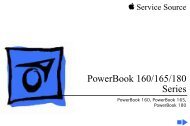
Block Diagram<br />
General Information<br />
<strong>Power</strong> <strong>Mac</strong> <strong>G5</strong> Troubleshooting - 4
Resetting the PMU on the Logic Board<br />
The PMU (<strong>Power</strong> Management Unit) is a microcontroller chip that controls all power<br />
functions for this computer. The PMU is a computer within a computer. Its function is to:<br />
• tell the computer to turn on, turn off, sleep, wake, idle, etc.<br />
• manage system resets from various commands.<br />
• maintain parameter RAM (PRAM).<br />
• manage the real-time clock.<br />
Important: Be very careful when handling the logic board. The PMU is very sensitive and<br />
touching the circuitry on the logic board can cause the PMU to crash. If the PMU crashes<br />
and is not reset, the battery life goes from about five years to about two days.<br />
Note: For the location of the PMU reset button, see “Logic Board Diagram” in the Views<br />
chapter.<br />
Many system problems can be resolved by resetting the PMU chip. When you have a<br />
computer that fails to power up, follow this procedure before replacing any modules:<br />
1. Disconnect the power cord and check the battery in the battery holder. The battery<br />
should read 3.3 to 3.7 volts. If the battery is bad, replace it, wait ten seconds, and then<br />
proceed to step 2. If the battery is good, go directly to step 2.<br />
2. Press the PMU reset button once and then proceed to step 3. Do not press the PMU<br />
reset button a second time because it could crash the PMU chip.<br />
3. Wait ten seconds before connecting the power cord and powering on the computer. If<br />
the computer does not power on, there is something else wrong with it; refer to the<br />
“System” section of “Symptom Charts” in this chapter.<br />
Note: The above procedure resets the computer’s PRAM. After resetting the PMU, be<br />
sure to reset the time, date, and other system parameter settings.<br />
RAM and Processor Verification: <strong>Power</strong>-On Self Test<br />
A power-on self test in the computer’s ROM automatically runs whenever the computer is<br />
started up after being fully shut down (the test does not run if the computer is only<br />
restarted). If the test detects a problem, the status LED located above the power button on<br />
the front of the computer will flash in the following ways:<br />
• 2 Flashes: No RAM is installed or detected.<br />
• 3 Flashes: Incompatible RAM types are installed.<br />
• 4 Flashes: No RAM banks passed memory testing.<br />
• 5 Flashes: No good boot images are detected in the boot ROM (and/or there is a bad<br />
sys config block).<br />
• 6 Flashes: The processor is not usable.<br />
General Information<br />
<strong>Power</strong> <strong>Mac</strong> <strong>G5</strong> Troubleshooting - 5
Pinouts<br />
<strong>Power</strong> Supply P1 Connector<br />
Pin # Signal Color Pin# Signal Color<br />
1 +5Vstb Purple 13 GND Black<br />
2 GND Black 14 <strong>Power</strong> ON Green<br />
3 FANtach White/Yellow 15 GND Black<br />
4 GND Black 16 Reserved<br />
5 Reserved 17 GND Black<br />
6 GND Black 18 RTNaud(GND) Black<br />
7 +12Vaud (12V2) Yellow 19 GND Black<br />
8 GND Black 20 +5V sense Red<br />
9 +3.3V sense Orange 21 GND Black<br />
10 GND Black 22 -12V Blue<br />
11 GND Black 23 GND Black<br />
12 Reserved 24 Reserved<br />
6 - <strong>Power</strong> <strong>Mac</strong> <strong>G5</strong> Troubleshooting General Information
<strong>Power</strong> Supply P2 Connector<br />
Pin# Signal Color Pin# Signal Color<br />
1 +3.3V Orange 9 +5V Red<br />
2 +3.3V Orange 10 +5V Red<br />
3 +3.3V Orange 11 +5V Red<br />
4 +3.3V Orange 12 +12V3 Yellow<br />
5 Reserve 13 +12V3 Yellow<br />
6 +12Vfan Yellow 14 +12V1 Yellow<br />
7 +12Vfan(12V2) Yellow 15 +12V1 Yellow<br />
8 +25V White 16 RTNfan(GND) Black<br />
<strong>Power</strong> Supply P3 Connector<br />
Pin# Signal Color Pin# Signal Color<br />
1 +5V Red 5 +5V Red<br />
2 GND Black 6 GND Black<br />
3 GND Black 7 GND Black<br />
4 12V2 Yellow 8 +12V2 Yellow<br />
General Information<br />
<strong>Power</strong> <strong>Mac</strong> <strong>G5</strong> Troubleshooting - 7
Front Inlet Fan Connector<br />
Pin#<br />
Signal<br />
1 FAN CPU Cpu AF MOTOR<br />
2 FAN CPU AF TACH<br />
3 FAN GND<br />
4 FAN 12V<br />
5 FAN CPU BF MOTOR<br />
6 FAN CPU BF TACK<br />
7 TEMP SENSE D-<br />
8 TEMP SENSE D+<br />
8 - <strong>Power</strong> <strong>Mac</strong> <strong>G5</strong> Troubleshooting General Information
Front Panel Board Connector<br />
Pin# Signal Type<br />
1 25V<br />
2 V-GND<br />
3 FW TPA Twisted Pair Shield 110 Ohm<br />
4 FW TPA + Twisted Pair Shield 110 Ohm<br />
5 CHASSIS GND FW<br />
6 CHASSIS GND USB<br />
7 FW TPB Twisted Pair Shield 100 Ohm<br />
8 FW TPB+ Twisted Pair Shield 100 Ohm<br />
9 USB PWR<br />
10 USB GND<br />
11 USB Twisted Pair Shield 60 Ohm<br />
12 USB+ Twisted Pair Shield 60 Ohm<br />
13 LED<br />
14 PWR BTN<br />
15 AUDIO SENSE<br />
16 AUDIO COM Twisted TRI<br />
17 AUDIO RIGHT Twisted TRI<br />
18 AUDIO LEFT Twisted TRI<br />
General Information<br />
<strong>Power</strong> <strong>Mac</strong> <strong>G5</strong> Troubleshooting - 9
Optical and Serial ATA Hard Drive Cable Connectors<br />
<strong>Power</strong> Optical SP1 (HD1) SP2 (HD2)<br />
Pin# Color Pin# Color Pin# Color Pin# Color<br />
1 BLK 4 BLK<br />
2 BLK 3 BLK<br />
3 BLK 1 BLK<br />
4 BLK 2 BLK 2 BLK<br />
5 BLK 3 BLK 3 BLK<br />
6 BLK 1 BLK 1 BLK<br />
7 BLK 4 BLK 4 BLK<br />
Media Bay Temperature Sensor Cable<br />
7 Pin Signal 5 Pin 4 Pin<br />
Connector Connector Connector<br />
1 3.3V 1 1<br />
2 [ ]G B CLK 2<br />
3 ] [G B DAT 2<br />
4 GND 4 2<br />
5 OVER TEMP 5<br />
6 DOOR AJAR 1 3<br />
7 3.3V SLEEP 4<br />
10 - <strong>Power</strong> <strong>Mac</strong> <strong>G5</strong> Troubleshooting General Information
Symptom Charts<br />
How to Use the Symptom Charts<br />
The Symptom Charts included in this chapter will help you diagnose specific symptoms<br />
related to the product. Because cures are listed on the charts in the order of most likely<br />
solution, try the cures in the order presented. Verify whether or not the product continues<br />
to exhibit the symptom. If the symptom persists, try the next cure.<br />
Note: If a cure instructs you to replace a module, reinstall the original module before you<br />
proceed to the next cure.<br />
Important: The only way to shut off power completely to the computer and display is to<br />
disconnect their power plugs from the power source. Make sure the power cords to the<br />
computer and display are within easy reach.<br />
Failures<br />
No power (no LED, no fans, no boot tone, no video)<br />
1. Verify power outlet is good<br />
2. Replace power cord<br />
3. Check power supply cables<br />
4. Check power rails for correct voltage<br />
5. Replace power supply<br />
6. Check front panel board cable<br />
7. Replace front panel board cable<br />
8. Replace front panel board<br />
9. Replace power button<br />
10. Replace logic board<br />
No LED (fans on, boot tone, video)<br />
1. Replace front panel board<br />
2. Replace power button<br />
Symptom Charts<br />
<strong>Power</strong> <strong>Mac</strong> <strong>G5</strong> Troubleshooting - 11
No power (LED on/off, no fans, no boot tone, no video)<br />
1. Check power supply cables<br />
2. Check logic board power rails<br />
3. Check processor connector<br />
4. Check logic board tape for dual config<br />
5. Replace power supply<br />
6. Replace processor<br />
7. Replace logic board<br />
No boot (LED on/off, fans spin, no boot tone, no video)<br />
1. Replace memory<br />
2. Replace logic board<br />
Memory (blinking LED, fans spin, no boot tone, no video)<br />
1. Check memory config and replace DIMMs<br />
2. Replace logic board<br />
No boot tone (LED on, fans spin, no boot tone, video) or<br />
No video (LED on, fans spin, boot tone, no video)<br />
1. Reseat video card<br />
2. Replace video card<br />
3. Replace front panel board cable<br />
4. Replace speaker<br />
5. Replace front panel board<br />
6. Replace logic board<br />
Duct door sensor<br />
1. Reseat interlock sensor board cable<br />
2. Replace interlock sensor board<br />
3. Replace logic board<br />
4. Replace enclosure<br />
12 - <strong>Power</strong> <strong>Mac</strong> <strong>G5</strong> Troubleshooting Symptom Charts
Optical drive<br />
1. Replace optical drive cable<br />
2. Replace optical drive<br />
3. Replace logic board<br />
FireWire port (front panel A)<br />
1. Replace front panel board cable<br />
2. Replace front panel board<br />
3. Replace logic board<br />
Firewire port (rear AB)<br />
Replace logic board<br />
Firewire port (rear BB)<br />
Replace logic board<br />
Internal speakers (left or right fails, boot tone)<br />
Replace logic board<br />
Internal speakers (high-pitch tone)<br />
1. Replace power supply<br />
2. Replace logic board<br />
USB 2.0 (front port)<br />
1. Replace front panel board cable<br />
2. Replace front panel board<br />
3. Replace logic board<br />
USB 2.0 (rear-top port)<br />
Replace logic board<br />
USB 2.0 (rear-bottom port)<br />
Replace logic board<br />
Symptom Charts<br />
<strong>Power</strong> <strong>Mac</strong> <strong>G5</strong> Troubleshooting - 13
Modem<br />
1. Replace modem<br />
2. Replace modem filter board<br />
3. Replace logic board<br />
AirPort<br />
1. Replace AirPort Card<br />
2. Replace antenna card<br />
3. Replace logic board<br />
Bluetooth<br />
1. Replace Bluetooth card<br />
2. Replace antenna card<br />
3. Replace logic board<br />
Audio IO (front line in headphones)<br />
1. Replace front panel board cable<br />
2. Replace front panel board<br />
3. Reposition logic board<br />
4. Replace logic board<br />
Audio IO (rear line in line out)<br />
Replace logic board<br />
Audio IO (rear line out line out)<br />
Replace logic board<br />
Fans<br />
1. Replace fan<br />
2. Replace logic board<br />
14 - <strong>Power</strong> <strong>Mac</strong> <strong>G5</strong> Troubleshooting Symptom Charts
apple <strong>Service</strong> <strong>Source</strong><br />
Views<br />
<strong>Power</strong> <strong>Mac</strong> <strong>G5</strong><br />
© 2003 Apple Computer, Inc. All rights reserved.
Exploded Views<br />
Exploded View 1<br />
Super Drive<br />
661-2908<br />
Combo Drive<br />
661-2909<br />
Optical Drive EMI Shield<br />
922-6036<br />
Speaker / Fan Bracket<br />
922-6029<br />
Speaker<br />
922-5959<br />
Fan<br />
076-1049<br />
Inlet / Processor Fan, Dual<br />
076-1046<br />
Inlet Fan Bracket, Dual<br />
922-6031<br />
Inlet / Processor Fan, Uni<br />
076-1048<br />
Inlet Fan Bracket, Uni<br />
922-6058<br />
<strong>Power</strong> Supply<br />
450W 661-2903<br />
600W 661-2904<br />
Video Card<br />
661-2912, 661-2921, 661-2922<br />
Fibre Channel Card<br />
661-1763<br />
<br />
Serial ATA Hard Drive<br />
80GB 661-2905<br />
160GB 661-2906<br />
250GB 661-2907<br />
Rear Exhaust Fan Bracket<br />
922-6033<br />
Rear Exhaust Fans<br />
076-1047<br />
Enclosure<br />
922-5952<br />
Exploded Views<br />
<strong>Power</strong> <strong>Mac</strong> <strong>G5</strong> Views - 1
Exploded View #2<br />
DC Heatsink Cover<br />
922-6025<br />
PCI Divider<br />
922-6207<br />
<strong>G5</strong> Heatsink Cap<br />
922-6026<br />
Processor, 1.6 GHz, Uni<br />
661-2899<br />
Processor, 1.8 GHz, Uni<br />
661-2900<br />
Processor, 2.0 GHz, Dual<br />
661-2901<br />
Logic Board, 167 MHz, Uni<br />
661-2894<br />
Logic Board, 233 MHz, Uni<br />
661-2895<br />
Logic Board, 233 MHz, Dua<br />
661-2950<br />
DIMMS, DDR 333<br />
128MB 661-2897<br />
256MB 661-2726<br />
512MB 661-2727<br />
1GB 661-2935<br />
DIMMS, DDR 400<br />
256MB 661-2898<br />
512MB 661-2934<br />
2 - <strong>Power</strong> <strong>Mac</strong> <strong>G5</strong> Views Exploded Views
Internal Views<br />
Overview<br />
Optical Drive<br />
Top Hard Drive Bay<br />
Battery<br />
Bottom Hard Drive Bay<br />
AirPort Extreme<br />
Card Connector<br />
Slots 2—4: PCI or PCI-X Slots<br />
(Depending on model)<br />
yyy<br />
yyy<br />
yyy<br />
yyy<br />
DDR SDRAM Slots<br />
(Either 4 or 8 Slots,<br />
depending on model)<br />
Slot 1: AGP 8X Pro Slot<br />
(Graphics card installed)<br />
Internal Views<br />
<strong>Power</strong> <strong>Mac</strong> <strong>G5</strong> Views - 3
Logic Board<br />
Optical Digital Audio In<br />
Optical Digital Audio Out<br />
BlueTooth Antenna<br />
AirPort Antenna<br />
AGP Slot 1<br />
PCI Slot 2<br />
PCI Slot 3<br />
PCI Slot 4<br />
Rear<br />
Exhaust<br />
Fan<br />
Connector<br />
Media<br />
Thermal<br />
Sensor<br />
Connector<br />
Audio Line Out<br />
Audio Line In<br />
USB 2.0 Port<br />
USB 2.0 Port<br />
FireWire 400 Port<br />
FireWire 800 Port<br />
Ether<strong>net</strong> Port<br />
Modem Port<br />
<strong>Power</strong><br />
Supply<br />
Connector<br />
Upper Hard Drive<br />
Connector<br />
Lower Hard Drive<br />
Connector<br />
Media Fan<br />
Connector<br />
Media Blower<br />
Connector<br />
Battery<br />
Processor<br />
Connectors<br />
Optical<br />
Drive<br />
Connector<br />
Speaker<br />
Connector<br />
PCI Fan<br />
Connector<br />
Modem Card<br />
Connector<br />
Bluetooth<br />
Connector<br />
<strong>Power</strong><br />
Supply<br />
Connector<br />
PMU<br />
Reset<br />
Button<br />
Front Panel<br />
Board<br />
Connector<br />
Front Inlet Fan<br />
Connector<br />
AirPort<br />
Connector<br />
DIMM Slots<br />
4 - <strong>Power</strong> <strong>Mac</strong> <strong>G5</strong> Views Internal Views
External Views<br />
Front View<br />
Optical Drive<br />
Status Light<br />
f Headphone Jack<br />
¤ <strong>Power</strong> Button<br />
FireWire 400 Port<br />
USB 2.0 Port<br />
External Views<br />
<strong>Power</strong> <strong>Mac</strong> <strong>G5</strong> Views - 5
Rear View<br />
Latch<br />
Access Covers for PCI<br />
Expansion Slots<br />
DVI Display Port<br />
ADC Display Port<br />
AirPort Antenna Port<br />
Optical Digital<br />
Audio Out Port<br />
Bluetooth Antenna Port<br />
USB 2.0 Ports (2)<br />
-<br />
Optical Digital<br />
Audio In Port<br />
Audio Line-Out Port<br />
FireWire 400 Port<br />
ˆ Audio Line-In Port<br />
FireWire 800 Port<br />
G<br />
Ether<strong>net</strong> Port<br />
<strong>Power</strong> Socket<br />
W<br />
Internal Modem Port<br />
(On some models)<br />
6 - <strong>Power</strong> <strong>Mac</strong> <strong>G5</strong> Views External Views