PowerBook 160/165/180 Series - Retrocomputing.net
PowerBook 160/165/180 Series - Retrocomputing.net
PowerBook 160/165/180 Series - Retrocomputing.net

You also want an ePaper? Increase the reach of your titles
YUMPU automatically turns print PDFs into web optimized ePapers that Google loves.
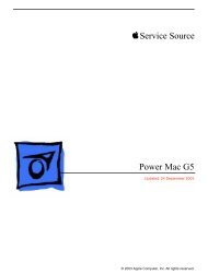
K Service Source<br />
<strong>PowerBook</strong> <strong>160</strong>/<strong>165</strong>/<strong>180</strong><br />
<strong>Series</strong><br />
<strong>PowerBook</strong> <strong>160</strong>, <strong>PowerBook</strong> <strong>165</strong>,<br />
<strong>PowerBook</strong> <strong>180</strong>
K Service Source<br />
Basics<br />
<strong>PowerBook</strong> <strong>160</strong>/<strong>165</strong>/<strong>180</strong>
Basics Overview - 1<br />
Overview<br />
This manual includes<br />
complete repair procedures<br />
for the <strong>PowerBook</strong> <strong>160</strong>,<br />
<strong>PowerBook</strong> <strong>165</strong>, and<br />
<strong>PowerBook</strong> <strong>180</strong>..<br />
Figure: <strong>PowerBook</strong> <strong>160</strong>, <strong>165</strong>, <strong>180</strong>
Basics Display Compatibility Matrix - 2<br />
Display Compatibility Matrix<br />
Active Matrix<br />
PB <strong>180</strong><br />
661-0748<br />
FSTN, Rev. A<br />
PB <strong>160</strong>/<strong>165</strong><br />
661-0745<br />
Inverter 922-0024 922-0025<br />
Display Cable 630-6273 922-0820<br />
Inverter Cable 936-0106 936-0106<br />
Important: <strong>PowerBook</strong> <strong>160</strong>/<strong>165</strong>/<strong>180</strong> family includes two<br />
displays—an active matrix and an FSTN display. Each of<br />
these displays requires a compatible inverter and display<br />
cable; the inverters, display cables, and displays are not<br />
interchangeable. Before ordering one of these parts, refer to<br />
the display matrix shown above.
K Service Source<br />
Specifications<br />
<strong>PowerBook</strong> <strong>160</strong>/<strong>165</strong>/<strong>180</strong>
Specifications Processor - 1<br />
Processor<br />
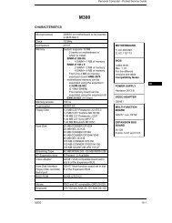
<strong>160</strong> CPU Motorola 68030 microprocessor<br />
25 MHz<br />
<strong>165</strong> CPU Motorola 68030 microprocessor<br />
33 MHz<br />
<strong>180</strong> CPU Motorola 68030 microprocessor<br />
33 MHz<br />
Coprocessor (<strong>180</strong><br />
Only)<br />
Motorola 68882 floating-point math coprocessor<br />
33 MHz
Specifications Processor - 2<br />
Addressing<br />
32-bit internal registers<br />
32-bit address bus<br />
32-bit data bus
Specifications Memory - 3<br />
Memory<br />
RAM<br />
4 MB pseudostatic RAM (PSRAM) installed on the daughterboard<br />
Expandable to 8 MB with 4 MB expansion card<br />
Expandable to 14 MB with third-party PSRAM expansion cards<br />
ROM<br />
1 MB<br />
PRAM<br />
256 bytes of parameter memory<br />
VRAM<br />
128K of static video display memory<br />
Clock/Calendar<br />
CMOS custom chip with long-life lithium battery
Specifications Disk Storage - 4<br />
Disk Storage<br />
Floppy Drive<br />
19 mm high, internal, 1.4 MB Apple SuperDrive<br />
Hard Drive<br />
2.5 in. hard drives (many capacities)
Specifications I/O Interfaces - 5<br />
I/O Interfaces<br />
Floppy Drive<br />
DB-19 serial port for connecting external floppy drives<br />
SCSI<br />
HDI-30 SCSI port with 1.5 MB/sec. transfer rate<br />
Supports up to five external SCSI devices<br />
Does not provide termination power<br />
Connect SCSI device to computer with HDI-30 SCSI system cable.<br />
Apple Desktop Bus<br />
Apple Desktop Bus (ADB) port (maximum of three ADB devices is<br />
recommended)<br />
200 mA maximum current draw for all ADB devices
Specifications I/O Interfaces - 6<br />
Serial<br />
Two RS-422 serial ports; mini DIN-8 connectors<br />
Sound<br />
Monaural sound-in port<br />
Stereo sound-out headphone jack, which plays CD audio tracks in<br />
stereo and computer-generated sounds in mono<br />
Video<br />
Video-out port; 8 bit, 256 color video support<br />
Supports Macintosh monitors up to 16-in. color and VGA monitors<br />
Power Adapter<br />
Power adapter port<br />
Security<br />
Slot for third-party security equipment<br />
Modem<br />
Slot for optional internal modem
Specifications I/O Devices - 7<br />
I/O Devices<br />
Keyboard<br />
Built-in keyboard with standard Macintosh layout<br />
63 keys domestic; 64 keys ISO<br />
Two-level tilt adjustment<br />
Trackball<br />
30 mm diameter, dual button<br />
ADB interface<br />
Microphone<br />
Electret, omnidirectional<br />
Output voltage of 4 mV, peak to peak
Specifications Sound and Video - 8<br />
Sound and Video<br />
Sound Generator<br />
Apple sound chip provides 8-bit sound capable of driving stereo<br />
headphones or other stereo equipment through the sound jack<br />
8-bit sound input, sampled at 11 or 22 kHz<br />
<strong>160</strong>/<strong>165</strong> Video<br />
Display<br />
10 in. (254 mm) diagonal screen<br />
Flat-panel, film-compensated supertwist nematic (FSTN) liquid<br />
crystal display<br />
CCFL on-demand backlight<br />
16 shades of gray; 640 by 400 pixels<br />
<strong>180</strong> Video Display 10 in. (254 mm) diagonal screen<br />
Flat-panel, active-matrix liquid crystal display<br />
CCFL on-demand backlight<br />
16 shades of gray; 640 by 400 pixels
Specifications Electrical - 9<br />
Electrical<br />
Main Battery<br />
Nickel cadmium (NiCad), 2.5 Ah<br />
Provides 2-3 hours of usage before recharging<br />
Recharge time: 3 hours<br />
500 power cycles capacity<br />
PRAM Battery<br />
3 V lithium<br />
Power Adapter<br />
110–220 VAC line voltage<br />
17 W, 50–60 Hz<br />
US, Japanese, United Kingdom, Australian, and European versions
Specifications Physical - 10<br />
Physical<br />
Dimensions<br />
Height: 2.25 in. (5.7 cm)<br />
Width: 11.25 in. (28.6 cm)<br />
Depth: 9.3 in. (23.6 cm)<br />
Weight<br />
6.8 lb. (3.1 kg) with battery
Specifications Environmental - 11<br />
Environmental<br />
Operating<br />
Temperature<br />
50–104° F (10-40° C)<br />
Storage<br />
Temperature<br />
-13 to 140° F (-25 to 60° C)<br />
Relative Humidity<br />
20–80% noncondensing<br />
Altitude 0–15,000 ft. (0–4722 m)<br />
Operational Altitude 0–10,000 ft. (0–3048 m)
Specifications Other - 12<br />
Other<br />
Fax/Data Modem<br />
Internal 2400-baud modem with fax send at 9600 baud (includes<br />
fax send software)<br />
300/1200/2400 bps transmission rates<br />
Serial binary and asynchronous protocols<br />
Error correction and data compression: MNP 4, 5 and V.42,<br />
V.42bis
Specifications Other - 13<br />
Express Modem Internal 14,400-baud modem with fax send/receive at 9600<br />
baud<br />
300-14,400 bps data transmission rates<br />
2400/4800/7200/9600 bps transmission rates<br />
Full duplex operation; asynchronous or framed modes<br />
Error correction: V.42 compliance (MNP 2-4)<br />
Data compression: V.42bis (4 to 1 compression) and MNP-5 (2<br />
to 1 compression)<br />
Requires 300K of system RAM<br />
SCSI Adapter<br />
Enables connection between <strong>PowerBook</strong> computer and desktop<br />
Macintosh (<strong>PowerBook</strong> appears as a hard drive on the desktop
K Service Source<br />
Troubleshooting<br />
<strong>PowerBook</strong> <strong>160</strong>/<strong>165</strong>/<strong>180</strong>
Troubleshooting General/ - 1<br />
General<br />
The Symptom Charts included in this chapter will help you<br />
diagnose specific symptoms related to your product. Because cures<br />
are listed on the charts in the order of most likely solution, try<br />
the first cure first. Verify whether or not the product continues to<br />
exhibit the symptom. If the symptom persists, try the next cure.<br />
(Note: If you have replaced a module, reinstall the original module<br />
before you proceed to the next cure.)<br />
If you are not sure what the problem is, or if the Symptom Charts<br />
do not resolve the problem, refer to the Flowchart for the product<br />
family.<br />
For additional assistance, contact Apple Technical Support.
Troubleshooting Power Manager Reset/ - 2<br />
Power Manager Reset<br />
Reset the power manager if<br />
• The battery and power adapter are proven good, but the<br />
computer will not power on.<br />
• The computer will not reset after a system crash.<br />
To reset the power manager in a <strong>PowerBook</strong> <strong>160</strong>/<strong>165</strong>/<strong>180</strong><br />
1 Remove the AC adapter and the battery.<br />
2 Let the unit sit without power hooked up for 3–5 minutes.<br />
3 Reinstall the battery and, if necessary, reconnect the AC<br />
adapter.<br />
4 Turn on the computer.
Troubleshooting Power Manager Reset/ - 3<br />
If this does not reset the power manager,<br />
5 Remove the AC adapter and the battery.<br />
6 Let the unit sit without power hooked up for 3–5 minutes.<br />
7 Using two paper clips, simultaneously hold down the reset<br />
and interrupt buttons for 5–10 seconds.<br />
8 Reinstall the battery and, if necessary, reconnect the AC<br />
adapter.<br />
9 Turn on the computer.
Troubleshooting Symptom Charts/Startup - 4<br />
Symptom Charts<br />
Startup<br />
RAM failure occurs<br />
(eight-tone error<br />
chord sequence<br />
sounds after startup<br />
chord)<br />
Hardware failure<br />
occurs (four-tone<br />
error chord sequence<br />
sounds after startup<br />
chord)<br />
1 Reseat PSRAM expansion card and check connection.<br />
2 Replace PSRAM expansion card.<br />
3 Replace daughterboard.<br />
4 Replace motherboard.<br />
1 Disconnect hard drive data cable and restart computer. If<br />
startup sequence is normal, reconnect cable and retest.<br />
2 Replace hard drive.<br />
3 Disconnect floppy drive cable and restart computer. If<br />
startup sequence is normal, reconnect cable and retest.<br />
4 Replace floppy drive.<br />
5 Replace motherboard.
Troubleshooting Symptom Charts/Startup - 5<br />
Startup<br />
Screen displays<br />
checkerboard pattern;<br />
no startup chime<br />
1 Reseat RAM expansion card.<br />
2 Replace RAM expansion card.<br />
3 Replace daughterboard.<br />
4 Reseat display cable.
Troubleshooting Symptom Charts/Power - 6<br />
Power<br />
Screen is blank;<br />
computer doesn’t<br />
respond<br />
1 Restart computer.<br />
2 Connect power adapter and restart computer in 3-4 minutes.<br />
3 Try known–good, charged main battery.<br />
4 Check all interconnect board, daughterboard, and<br />
motherboard connections.<br />
5 Reset the power manager.<br />
6 Replace keyboard.<br />
7 Replace interconnect board.<br />
8 Replace daughterboard.<br />
9 Replace motherboard.
Troubleshooting Symptom Charts/Power - 7<br />
Power<br />
After you remove<br />
main battery, some<br />
Control Panel<br />
settings are different<br />
Power adapter is<br />
plugged in, but<br />
battery DA does not<br />
indicate charger is<br />
connected<br />
1 Check cables.<br />
2 Replace interconnect board.<br />
3 Replace daughterboard.<br />
4 Replace motherboard.<br />
1 This is normal for fully charged battery.<br />
2 Check battery charger connection.<br />
3 Try known-good, charged main battery.<br />
4 Try known-good power adapter.<br />
5 Check battery thermistor cable connection.<br />
6 Replace motherboard.
Troubleshooting Symptom Charts/Power - 8<br />
Power<br />
Low-power warning<br />
appears<br />
Computer runs when<br />
plugged into wall<br />
outlet but not on<br />
battery power;<br />
battery voltage is<br />
within tolerance<br />
1 Recharge battery or attach power adapter.<br />
2 Verify that peripherals are low-power.<br />
3 Remove external devices or connect power adapter.<br />
4 Try known-good, charged main battery.<br />
5 Try known-good power adapter.<br />
6 Replace motherboard.<br />
1 Reseat battery to make sure it is mating with contacts on<br />
motherboard.<br />
2 If motherboard includes removable fuse, replace fuse.<br />
3 Replace motherboard.<br />
4 Return computer to Apple.
Troubleshooting Symptom Charts/Video - 9<br />
Video<br />
Pixel is always white <strong>PowerBook</strong> <strong>180</strong><br />
If there are more than five voids (pixels that are always white),<br />
or two or more voids within one inch of each other, replace<br />
display (CPRC/international repairers only) or return computer<br />
to Apple.<br />
<strong>PowerBook</strong>s <strong>160</strong> and <strong>165</strong><br />
Replace display.<br />
Pixel is always black <strong>PowerBook</strong> <strong>180</strong><br />
Replace display (CPRC/international repairers only) or return<br />
computer to Apple.<br />
<strong>PowerBook</strong>s <strong>160</strong> and <strong>165</strong><br />
Replace display.
Troubleshooting Symptom Charts/Video - 10<br />
Video<br />
Row or partial row of<br />
pixels never comes<br />
on (white line)<br />
<strong>PowerBook</strong> <strong>160</strong>/<strong>165</strong><br />
1 Check cables.<br />
2 Replace display cable.<br />
3 Replace display. If <strong>PowerBook</strong> has serial number below<br />
FC247xxxxxx or CK247xxxxxx, replace both display and<br />
daughterboard. (Do not replace Rev. B daughterboard.)<br />
4 Replace interconnect board.<br />
<strong>PowerBook</strong> <strong>180</strong><br />
5 Check cables.<br />
6 Replace display cable.<br />
7 Replace display (CPRC/international repairers only) and<br />
install System Enabler, v. 1.01.<br />
8 Replace interconnect board.<br />
9 Return computer to Apple.
Troubleshooting Symptom Charts/Video - 11<br />
Video<br />
Row or partial row of<br />
pixels is always on<br />
(black line)<br />
<strong>PowerBook</strong> <strong>160</strong>/<strong>165</strong><br />
1 Check cables.<br />
2 Replace display cable.<br />
3 Replace display.<br />
4 Replace interconnect board.<br />
<strong>PowerBook</strong> <strong>180</strong><br />
5 Check cables.<br />
6 Replace display cable.<br />
7 Replace interconnect board.<br />
8 Replace display (CPRC/international only) or return<br />
computer to Apple.
Troubleshooting Symptom Charts/Video - 12<br />
Video<br />
Thin white line is<br />
always on at middle of<br />
screen<br />
<strong>PowerBook</strong><strong>160</strong>/<strong>165</strong><br />
Thin white line is normal.<br />
<strong>PowerBook</strong> <strong>180</strong><br />
Replace display (CPRC/international repairers only) or return<br />
computer to Apple.
Troubleshooting Symptom Charts/Video - 13<br />
Video<br />
Display is very light<br />
or totally white<br />
1 Adjust screen contrast.<br />
2 Check display cable, inverter board, interconnect board,<br />
daughterboard, and motherboard connections.<br />
3 Replace inverter board.<br />
4 Replace interconnect board.<br />
5 Replace display cable.<br />
6 <strong>PowerBook</strong> <strong>160</strong>/<strong>165</strong>: Replace display.<br />
7 Replace daughterboard.<br />
8 Replace motherboard.<br />
9 <strong>PowerBook</strong> <strong>180</strong>: Replace display (CPRC/international<br />
repairers only) or return computer to Apple.
Troubleshooting Symptom Charts/Video - 14<br />
Video<br />
Rainbow colors<br />
visible from extreme<br />
viewing angles<br />
Screen brightness is<br />
not uniform<br />
<strong>PowerBook</strong> <strong>160</strong>/<strong>165</strong><br />
Such colors are normal for FSTN screens.<br />
<strong>PowerBook</strong> <strong>160</strong>/<strong>165</strong><br />
Irregularity in screen brightness is normal. Adjust contrast and<br />
brightness to diminish effect.<br />
<strong>PowerBook</strong> <strong>180</strong>:<br />
Replace display (CPRC/international repairers only) or return<br />
computer to Apple.
Troubleshooting Symptom Charts/Video - 15<br />
Video<br />
Display stopped<br />
working or dimmed<br />
but is fine now<br />
<strong>PowerBook</strong> <strong>160</strong>/<strong>165</strong><br />
If temperature is in the approximate range of under 5 or over 40<br />
degrees centigrade, this reaction is normal.
Troubleshooting Symptom Charts/Video - 16<br />
Video<br />
Backlight doesn’t<br />
operate<br />
1 Verify that cables are not pinched or severed.<br />
2 Check display cable, inverter board, interconnect board,<br />
daughterboard, and motherboard connections.<br />
3 Replace inverter board.<br />
4 Replace inverter display cable.<br />
5 Replace interconnect board.<br />
6 Replace display cable.<br />
7 <strong>PowerBook</strong> <strong>160</strong>/<strong>165</strong>: Replace display.<br />
8 Replace daughterboard.<br />
9 Replace motherboard.<br />
10 <strong>PowerBook</strong> <strong>180</strong>: Replace display (CPRC/international<br />
repairers only) or return computer to Apple.
Troubleshooting Symptom Charts/Video - 17<br />
Video<br />
Screen goes blank 1 Press any key to wake computer from system sleep.<br />
2 Check display cable connection.<br />
3 Reseat daughterboard.<br />
4 Replace daughterboard.
Troubleshooting Symptom Charts/Video - 18<br />
Video<br />
No display, but<br />
computer appears to<br />
operate correctly<br />
1 Adjust screen contrast.<br />
2 Check display cable, inverter board, interconnect board,<br />
daughterboard, and motherboard connections.<br />
3 Connect power adapter.<br />
4 Replace inverter board.<br />
5 Replace interconnect board.<br />
6 Replace display cable.<br />
7 <strong>PowerBook</strong> <strong>160</strong>/<strong>165</strong>: Replace display.<br />
8 Replace daughterboard.<br />
9 Replace motherboard.<br />
10 <strong>PowerBook</strong> <strong>180</strong>: Replace display (CPRC/international<br />
repairers only) or return computer to Apple.
Troubleshooting Symptom Charts/Video - 19<br />
Video<br />
Audio and video<br />
present, but internal<br />
floppy drive does not<br />
operate<br />
1 Try known-good floppy disk.<br />
2 Check floppy drive cable connection.<br />
3 Replace floppy drive cable.<br />
4 Replace floppy drive.<br />
5 Replace daughterboard.<br />
6 Replace motherboard.
Troubleshooting Symptom Charts/Hard Drive - 20<br />
Hard Drive<br />
Internal hard drive<br />
does not operate<br />
1 Disconnect external SCSI devices.<br />
2 Check internal hard drive cable connection.<br />
3 Use HD SC Setup to reinitialize drive.<br />
4 Replace internal hard drive cable.<br />
5 Replace internal hard drive.<br />
6 Replace motherboard.
Troubleshooting Symptom Charts/Floppy Drive - 21<br />
Floppy Drive<br />
Audio and video<br />
present, but internal<br />
floppy drive does not<br />
operate<br />
Disk ejects while<br />
booting; display<br />
shows Mac icon with<br />
blinking X<br />
1 Try known-good floppy disk.<br />
2 Check floppy drive cable connection.<br />
3 Replace floppy drive cable.<br />
4 Replace floppy drive.<br />
5 Replace daughterboard.<br />
6 Replace motherboard.<br />
1 Try known-good system disk.<br />
2 Verify that trackball or mouse button is not stuck.<br />
3 Check floppy drive cable connection.<br />
4 Replace floppy drive cable.<br />
5 Replace floppy drive.<br />
6 Replace motherboard.
Troubleshooting Symptom Charts/Floppy Drive - 22<br />
Floppy Drive<br />
Disk does not eject 1 Switch off system and hold mouse button down while you<br />
switch system on.<br />
2 Insert opened paper clip into hole beside drive.<br />
3 Check floppy drive cable connection.<br />
4 Replace floppy drive cable.<br />
5 Replace floppy drive.<br />
6 Replace daughterboard.<br />
7 Replace motherboard.<br />
Disk initialization<br />
fails<br />
1 Try known-good floppy disk.<br />
2 Install inverter shield (if absent).<br />
3 Check floppy drive cable connection.<br />
4 Replace floppy drive cable.<br />
5 Replace floppy drive.
Troubleshooting Symptom Charts/Floppy Drive - 23<br />
Floppy Drive<br />
Read/write/copy<br />
error<br />
1 Try known-good floppy disk.<br />
2 Install inverter shield if absent.<br />
3 Check floppy drive cable connection.<br />
4 Replace floppy drive cable.<br />
5 Replace floppy drive.
Troubleshooting Symptom Charts/Peripherals - 24<br />
Peripherals<br />
After you connect<br />
external SCSI device,<br />
computer does not<br />
boot<br />
Cursor does not move<br />
when you are using<br />
trackball<br />
1 Switch on external SCSI device before starting computer.<br />
2 Check cable connections.<br />
3 Verify that standard Apple terminator terminates SCSI chain<br />
at beginning and end.<br />
4 Verify that SCSI select switch setting on external device is<br />
unique.<br />
5 Verify operation of internal hard drive.<br />
6 Try known-good external SCSI device.<br />
7 Replace motherboard.<br />
1 Restart computer.<br />
2 Check cables.<br />
3 Check interconnect board, daughterboard, and motherboard<br />
connections.<br />
4 Try low-power mouse. If cursor moves, replace trackball or<br />
keyboard.
Troubleshooting Symptom Charts/Peripherals - 25<br />
Peripherals<br />
1 Replace interconnect board.<br />
2 Replace daughterboard.<br />
3 Replace motherboard.<br />
Cursor intermittently<br />
does not move or<br />
moves erratically<br />
1 Restart computer.<br />
2 Clean ball and rollers of trackball.<br />
3 Check cables.<br />
4 Replace trackball.<br />
5 Replace keyboard.<br />
6 Replace interconnect board.<br />
7 Replace motherboard.
Troubleshooting Symptom Charts/Peripherals - 26<br />
Peripherals<br />
Cursor moves, but<br />
clicking trackball<br />
button has no effect<br />
Cursor does not move<br />
when you are using<br />
mouse<br />
1 Restart computer.<br />
2 Check interconnect board, daughterboard, and motherboard<br />
connections.<br />
3 Replace trackball.<br />
4 Replace keyboard.<br />
5 Replace interconnect board.<br />
6 Replace daughterboard.<br />
7 Replace motherboard.<br />
1 Check mouse connection to ADB port.<br />
2 Restart computer.<br />
3 Clean mouse ball and inside mouse.<br />
4 Replace mouse.<br />
5 Replace motherboard.
Troubleshooting Symptom Charts/Peripherals - 27<br />
Peripherals<br />
No response to any<br />
key on keyboard<br />
Known-good directconnect<br />
printer does<br />
not print<br />
1 Reset power manager.<br />
2 Check connections of keyboard to interconnect board, and<br />
interconnect board to daughterboard.<br />
3 Replace keyboard.<br />
4 Replace interconnect board.<br />
5 Replace daughterboard.<br />
1 Verify that System is 7.1 or later.<br />
2 Verify that Chooser and Control Panel settings are correct.<br />
3 Check cables.<br />
4 Replace printer interface cable.<br />
5 Try known-good printer.<br />
6 Replace daughterboard.<br />
7 Replace motherboard.
Troubleshooting Symptom Charts/Peripherals - 28<br />
Peripherals<br />
Known-good <strong>net</strong>work<br />
printer does not print<br />
Device connected to<br />
external modem port<br />
doesn’t work<br />
1 Verify that System is 7.1 or later.<br />
2 Verify that Chooser and Control Panel settings are correct.<br />
3 Check cables.<br />
4 Replace printer interface cable.<br />
5 Try known-good printer. If printer works, troubleshoot<br />
<strong>net</strong>work. Refer to Networks manual.<br />
6 Replace daughterboard.<br />
7 Replace motherboard.<br />
1 Verify that External Modem is selected in CDEV.<br />
2 Verify that System is 7.1 or later.<br />
3 Check cables.<br />
4 Test device with known-good computer.<br />
5 Replace daughterboard.<br />
6 Replace motherboard.
Troubleshooting Symptom Charts/Peripherals - 29<br />
Peripherals<br />
I/O devices are<br />
unrecognized or<br />
garbage is<br />
transmitted or<br />
received<br />
1 Verify that System is 7.1 or later.<br />
2 Check cables.<br />
3 Verify that SCSI device has standard Apple terminator.<br />
4 Verify that SCSI select switch setting on external device is<br />
unique.<br />
5 Test device with known-good computer.<br />
6 Replace daughterboard.<br />
7 Replace motherboard.
Troubleshooting Symptom Charts/Internal Modem - 30<br />
Internal Modem<br />
Internal modem<br />
options do not appear<br />
in CDEV<br />
Modem does not<br />
respond properly to<br />
AT command set<br />
instructions<br />
1 Remove and reseat modem card.<br />
2 Verify that System is 7.1 or later.<br />
3 Replace modem card.<br />
4 Replace motherboard.<br />
1 Verify that baud rate and data format settings of<br />
communications application are compatible with internal<br />
modem and remote modem.<br />
2 Check phone cord connection and operation.<br />
3 Remove and reseat modem card.<br />
4 Verify that System is 7.1 or later.<br />
5 Replace modem card.
Troubleshooting Symptom Charts/Internal Modem - 31<br />
Internal Modem<br />
Strange mix of<br />
characters appears<br />
on screen<br />
Modem interferes<br />
with system sound<br />
1 Verify that baud rate and data format settings of<br />
communications application are compatible with internal<br />
modem and remote modem.<br />
2 Check phone cord connection and operation.<br />
3 Remove and reseat modem card.<br />
4 Verify that System is 7.1 or later.<br />
5 Replace modem card.<br />
6 Replace daughterboard.<br />
7 Replace motherboard.<br />
1 Remove and reseat modem card.<br />
2 Replace modem board.<br />
3 Replace interconnect card.<br />
4 Replace motherboard.
Troubleshooting Symptom Charts/Internal Modem - 32<br />
Internal Modem<br />
Modem does not<br />
respond to incoming<br />
call<br />
Modem has no sound<br />
output<br />
Modem connects but<br />
does not communicate<br />
with remote modem<br />
1 If computer is in sleep mode, verify that Wake On Ring<br />
option in CDEV is selected.<br />
2 Check phone cord connection and operation.<br />
3 Replace modem card.<br />
4 Replace motherboard.<br />
1 Verify that Control Panel volume setting is above 0.<br />
2 Replace modem card.<br />
3 Replace interconnect card.<br />
4 Replace motherboard.<br />
1 Verify that remote modem needs error correction (error<br />
correction is internal modem default).<br />
2 Type “AT &Q0” to disable error correction.
Troubleshooting Symptom Charts/Miscellaneous - 33<br />
Miscellaneous<br />
Screen goes blank and<br />
computer shuts down<br />
every few minutes<br />
Application seems to<br />
run slower after few<br />
seconds<br />
Hard drive is slow to<br />
respond, or screen<br />
goes blank too often<br />
Adjust sleep delays in Control Panel or connect power adapter.<br />
1 Disable System Rest. (See owner’s manual.)<br />
2 Connect power adapter.<br />
Adjust sleep delays in Control Panel or connect power adapter.
Troubleshooting Symptom Charts/Miscellaneous - 34<br />
Miscellaneous<br />
No sound from<br />
speaker<br />
1 Verify that volume setting in Control Panel is above 0.<br />
2 Verify that no external speaker is plugged in.<br />
3 Check connections of speaker to interconnect board,<br />
interconnect board to daughterboard, and daughterboard to<br />
motherboard.<br />
4 Replace interconnect board.<br />
5 Replace daughterboard.<br />
6 Replace motherboard.
K Service Source<br />
Take Apart<br />
<strong>PowerBook</strong> <strong>160</strong>/<strong>165</strong>/<strong>180</strong>
Take Apart Main Battery - 1<br />
Main Battery<br />
Before you begin,<br />
disconnect the power<br />
adapter.<br />
Note: This procedure also<br />
covers removal of the main<br />
battery door.<br />
Important: Before removing<br />
the main battery, use the<br />
Macintosh Shut Down<br />
command. Otherwise, all<br />
RAM contents will be lost.<br />
Main Battery
Take Apart Main Battery - 2<br />
±Warning: The main<br />
battery contains toxic<br />
materials. Review<br />
battery-handling and<br />
disposal instructions in<br />
Bulletins/Safety.<br />
1 Slide open the battery<br />
door.<br />
2 Using the battery door as<br />
a handle, pull out the<br />
main battery.
Take Apart Main Battery - 3<br />
3 Slide the battery door<br />
completely open.<br />
4 Pull the end tab until it<br />
releases and remove the<br />
door from the battery.<br />
End Tab
Take Apart I/O Door - 4<br />
I/O Door<br />
No preliminary steps are<br />
required before you begin<br />
this procedure.<br />
Caution: The <strong>PowerBook</strong><br />
<strong>160</strong>/<strong>165</strong>/<strong>180</strong> contains<br />
CMOS devices that are very<br />
susceptible to ESD damage.<br />
Review the ESD precautions<br />
in Bulletins/Safety.<br />
I/O Door
Take Apart I/O Door - 5<br />
1 Open the I/O door.<br />
Right Door<br />
Peg<br />
2 Carefully bend the door<br />
so that the middle bows<br />
downward and unhinge<br />
the two bottom door pegs.
Take Apart Top Case - 6<br />
Top Case<br />
Before you begin, remove<br />
the following:<br />
• Main battery<br />
• I/O door<br />
Top Case<br />
Caution: The <strong>PowerBook</strong><br />
<strong>160</strong>/<strong>165</strong>/<strong>180</strong> contains<br />
CMOS devices that are very<br />
susceptible to ESD damage.<br />
Review the ESD precautions<br />
in Bulletins/Safety.
Take Apart Top Case - 7<br />
Note: Use a T-8 torx driver<br />
to remove the small screw<br />
from the rear connector<br />
panel and a T-10 torx<br />
driver to remove the other<br />
case screws.<br />
1 Remove the five torx<br />
screws from the bottom<br />
case.
Take Apart Top Case - 8<br />
2 Lift the back of the top<br />
case and disconnect the<br />
interconnect cable.<br />
Interconnect<br />
Cable<br />
3 Lift off the top case and<br />
unhook the two tab<br />
fasteners from the front<br />
of the bottom case.<br />
Replacement Caution:<br />
When connecting the display<br />
cable connector, fold the<br />
cable as shown. If it is not<br />
folded correctly, the cable<br />
could short.<br />
Tab Fastener
Take Apart Trackball Assembly - 9<br />
Trackball<br />
Assembly<br />
Trackball<br />
Assembly<br />
Before you begin, remove<br />
the following:<br />
• Main battery<br />
• I/O door<br />
• Top case<br />
Caution: The <strong>PowerBook</strong><br />
<strong>160</strong>/<strong>165</strong>/<strong>180</strong> contains<br />
CMOS devices that are very<br />
susceptible to ESD damage.<br />
Review the ESD precautions<br />
in Bulletins/Safety.
Take Apart Trackball Assembly - 10<br />
Trackball<br />
Ribbon Cable<br />
Locking<br />
Tab<br />
Caution: The trackball<br />
ribbon cable is fragile and<br />
should be handled with care.<br />
1 Pull out the locking tab<br />
on the trackball<br />
connector and remove<br />
the trackball ribbon<br />
cable.
Take Apart Trackball Assembly - 11<br />
2 Using a T-8 torx driver,<br />
remove the two mounting<br />
screws and lift the<br />
trackball assembly<br />
from the top case.
Take Apart Keyboard - 12<br />
Keyboard<br />
Keyboard<br />
Before you begin, remove<br />
the following:<br />
• Main battery<br />
• I/O door<br />
• Top case<br />
• Trackball assembly<br />
Caution: The <strong>PowerBook</strong><br />
<strong>160</strong>/<strong>165</strong>/<strong>180</strong> contains<br />
CMOS devices that are very<br />
susceptible to ESD damage.<br />
Review the ESD precautions<br />
in Bulletins/Safety.
Take Apart Keyboard - 13<br />
Caution: The keyboard<br />
ribbon cables are fragile and<br />
should be handled with care.<br />
Keyboard<br />
Ribbon Cables<br />
1 Lift the locking tabs on<br />
the two keyboard<br />
connectors and remove<br />
the keyboard ribbon<br />
cables.
Take Apart Keyboard - 14<br />
2 Using a T-8 torx driver,<br />
remove the seven<br />
mounting screws and<br />
lift the keyboard from<br />
the top case.
Take Apart Inverter Board - 15<br />
Inverter Board<br />
Before you begin, remove<br />
the following:<br />
• Main battery<br />
• I/O door<br />
• Top case<br />
Inverter Board<br />
Caution: The <strong>PowerBook</strong><br />
<strong>160</strong>/<strong>165</strong>/<strong>180</strong> contains<br />
CMOS devices that are very<br />
susceptible to ESD damage.<br />
Review the ESD precautions<br />
in Bulletins/Safety.
Take Apart Inverter Board - 16<br />
Important: The <strong>PowerBook</strong><br />
<strong>160</strong>/<strong>165</strong> and <strong>PowerBook</strong><br />
<strong>180</strong> displays require<br />
different inverter boards.<br />
Refer to the Service Source<br />
parts database for the<br />
correct part number for<br />
each board.
Take Apart Inverter Board - 17<br />
1 Remove the two<br />
mounting screws.<br />
Inverter<br />
Shield<br />
Inverter<br />
Board<br />
Inverter<br />
Cable<br />
Note: Do not remove the<br />
inverter shield from the<br />
inverter board.<br />
2 Pull the inverter board<br />
and attached shield<br />
straight up and off the<br />
connector on the<br />
interconnect board.<br />
3 Disconnect the inverter<br />
cable.
Take Apart Inverter Board - 18<br />
Brightness Pot<br />
Contrast Pot<br />
Inverter<br />
Board<br />
Replacement Note: Be sure<br />
to align the brightness and<br />
contrast pots on the inverter<br />
board with the plastic<br />
actuators on the top case. It<br />
is easiest to align the pots<br />
and actuators if you set both<br />
to their extreme outer<br />
positions.<br />
Actuator<br />
Actuator
Take Apart Inverter Board - 19<br />
Inverter Shield<br />
Inverter<br />
Board<br />
Replacement Note: If you<br />
are replacing the inverter<br />
board, order both the<br />
inverter board and the<br />
inverter shield. Install the<br />
new shield on the board<br />
before replacing it. Do not<br />
reuse the original inverter<br />
shield.
Take Apart Interconnect Board - 20<br />
Interconnect Board<br />
Before you begin, remove<br />
the following:<br />
• Main battery<br />
• I/O door<br />
• Top case<br />
• Inverter board<br />
Caution: The <strong>PowerBook</strong><br />
<strong>160</strong>/<strong>165</strong>/<strong>180</strong> contains<br />
CMOS devices that are very<br />
susceptible to ESD damage.<br />
Review the ESD precautions<br />
in Bulletins/Safety.<br />
Interconnect Board
Take Apart Interconnect Board - 21<br />
J5 Connector<br />
±Warning: The<br />
interconnect board contains<br />
hazardous materials.<br />
Return bad interconnect<br />
boards to Apple for proper<br />
disposal.<br />
J3 Connector<br />
Caution: The keyboard and<br />
display cables are fragile<br />
and should be handled with<br />
care.<br />
1 Lift the locking tabs on<br />
connectors J5 and J3 and<br />
remove the keyboard<br />
ribbon cables.
Take Apart Interconnect Board - 22<br />
Note: The display cable will<br />
not come entirely out of the<br />
connector until you remove<br />
the interconnect board from<br />
the top case.<br />
2 Pull out the locking tab<br />
on connector J2 and ease<br />
the display cable out of<br />
the connector as far as<br />
the cable will go.<br />
J2 Connector<br />
Replacement Note: Connect<br />
the display cable before<br />
replacing the interconnect<br />
board.
Take Apart Interconnect Board - 23<br />
3 Using a T-8 torx driver,<br />
remove the two mounting<br />
screws and lift the<br />
interconnect board from<br />
the top case.
Take Apart Actuators - 24<br />
Actuators<br />
Actuators<br />
Before you begin, remove<br />
the following:<br />
• Main battery<br />
• I/O door<br />
• Top case<br />
• Inverter board<br />
Caution: The <strong>PowerBook</strong><br />
<strong>160</strong>/<strong>165</strong>/<strong>180</strong> contains<br />
CMOS devices that are very<br />
susceptible to ESD damage.<br />
Review the ESD precautions<br />
in Bulletins/Safety.
Take Apart Actuators - 25<br />
1 Pull up the contrast<br />
actuator, rotate it<br />
toward the display, and<br />
remove the actuator<br />
from the top case.<br />
2 Repeat for the<br />
brightness actuator.
Take Apart Elevation Feet - 26<br />
Elevation Feet<br />
Before you begin, remove<br />
the following:<br />
• Main battery<br />
• I/O door<br />
• Top case<br />
Elevation Foot<br />
Caution: The <strong>PowerBook</strong><br />
<strong>160</strong>/<strong>165</strong>/<strong>180</strong> contains<br />
CMOS devices that are very<br />
susceptible to ESD damage.<br />
Review the ESD precautions<br />
in Bulletins/Safety.<br />
Elevation Foot
Take Apart Elevation Feet - 27<br />
Spring<br />
Clip<br />
1 Using a T-8 torx driver,<br />
remove the torx screw,<br />
washer, and spring clip<br />
from the inside of the<br />
elevation foot.<br />
2 Pull off the elevation<br />
foot.<br />
Elevation<br />
Foot
Take Apart Daughterboard - 28<br />
Daughterboard<br />
Before you begin, remove<br />
the following:<br />
• Main battery<br />
• I/O door<br />
• Top case<br />
• PSRAM expansion card<br />
(if present)<br />
Caution: The <strong>PowerBook</strong><br />
<strong>160</strong>/<strong>165</strong>/<strong>180</strong> contains<br />
CMOS devices that are very<br />
susceptible to ESD damage.<br />
Review the ESD precautions<br />
in Bulletins/Safety.<br />
Daughterboard
Take Apart Daughterboard - 29<br />
Daughterboard<br />
Motherboard<br />
1 Using a T-8 torx driver,<br />
remove the four<br />
daughterboard mounting<br />
screws.<br />
Logic Board<br />
Take-Apart<br />
Tool<br />
Caution: Always use the<br />
logic board take-apart tool<br />
to separate the<br />
daughterboard connector<br />
from the motherboard<br />
connector. Trying to<br />
disconnect the<br />
daughterboard from the<br />
motherboard by rocking or<br />
peeling the boards apart<br />
damages the connectors.
Take Apart Daughterboard - 30<br />
2 Using the Apple logic<br />
board take-apart tool,<br />
disconnect the<br />
daughterboard from the<br />
motherboard.<br />
U27<br />
Replacement Note: If you<br />
are replacing a defective<br />
daughterboard, be aware<br />
that the <strong>PowerBook</strong> <strong>160</strong>/<br />
<strong>165</strong>/<strong>180</strong> daughterboards<br />
are very similar. To<br />
differentiate<br />
daughterboards, check the<br />
underside of the board.<br />
<strong>PowerBook</strong> <strong>180</strong><br />
daughterboards have an FPU<br />
chip soldered at location
Take Apart Daughterboard - 31<br />
U27; <strong>PowerBook</strong> <strong>160</strong>/<strong>165</strong><br />
boards do not.<br />
To further differentiate<br />
<strong>PowerBook</strong> <strong>160</strong> and <strong>165</strong><br />
daughterboards, check the<br />
underside for the following<br />
resistors:<br />
• <strong>PowerBook</strong> <strong>160</strong><br />
daughterboard<br />
R38 resistor: installed<br />
R39 resistor: not<br />
installed<br />
• <strong>PowerBook</strong> <strong>165</strong><br />
daughterboard<br />
R38 resistor: not<br />
installed
Take Apart Daughterboard - 32<br />
R39 resistor: installed<br />
Heat Sinks<br />
For daughterboard part<br />
numbers, refer to the<br />
Service Source parts<br />
database.<br />
Heat Sink<br />
Replacement Note: The<br />
green heat sinks attached to<br />
the daughterboard are made<br />
of delicate heat-conducting<br />
material. If they are missing<br />
or damaged, they must be<br />
replaced.<br />
Daughterboard<br />
Replacement Note: To<br />
replace a damaged heat sink,<br />
carefully peel it from the<br />
daughterboard. Select the
Take Apart Daughterboard - 33<br />
appropriately sized heat<br />
sink from the heat sink kit<br />
(part number 076-0069),<br />
and gently press the part<br />
into place.<br />
Replacement Caution: Make<br />
sure the heat sink is placed<br />
exactly as shown in the<br />
illustration. The heat sink<br />
should not hang over the side<br />
of the component it is<br />
covering, or it may short<br />
the component leads.
Take Apart Daughterboard - 34<br />
Sound Jack Insulator<br />
Sound Jack<br />
Assembly<br />
Replacement Note: If you<br />
are replacing a defective<br />
daughterboard in a<br />
<strong>PowerBook</strong> <strong>160</strong>/<strong>180</strong><br />
within the serial number<br />
range FC233xxxxxx<br />
through FC241xxxxxx, you<br />
must also replace the sound<br />
jack insulator on the<br />
motherboard.<br />
Motherboard
Take Apart Daughterboard - 35<br />
Replacement Note: To<br />
replace the sound jack<br />
insulator, carefully peel off<br />
the original insulator.<br />
Remove the paper backing on<br />
the revised insulator (part<br />
number 922-0591), and<br />
gently press it into place.<br />
Replacement Caution: Make<br />
sure the new insulator sits<br />
in exactly the same position<br />
as the original insulator.
Take Apart Motherboard - 36<br />
Motherboard<br />
Motherboard<br />
Before you begin, remove<br />
the following:<br />
• Main battery<br />
• I/O door<br />
• Top case<br />
• PSRAM expansion card<br />
(if present)<br />
• Daughterboard<br />
• Modem card (if present)<br />
Caution: The <strong>PowerBook</strong><br />
<strong>160</strong>/<strong>165</strong>/<strong>180</strong> contains<br />
CMOS devices that are very<br />
susceptible to ESD damage.<br />
Review the ESD precautions<br />
in Bulletins/Safety.
Take Apart Motherboard - 37<br />
Floppy Drive Cable<br />
Thermistor Cable<br />
Hard Drive<br />
Cable<br />
Caution: The hard drive,<br />
floppy drive, and thermistor<br />
cables are fragile and<br />
should be handled with care.<br />
1 Lift the locking tabs and<br />
remove the floppy drive<br />
and thermistor cables.<br />
2 Remove the hard drive<br />
cable.<br />
Locking Tab<br />
Locking<br />
Tab
Take Apart Motherboard - 38<br />
Hex-Head Screw<br />
Motherboard<br />
3 Remove the two hexhead<br />
screws and lift the<br />
motherboard from the<br />
bottom case.
Take Apart Hard Drive - 39<br />
Hard Drive<br />
Before you begin, remove<br />
the following:<br />
• Main battery<br />
• I/O door<br />
• Top case<br />
• Modem card (if present)<br />
• Daughterboard<br />
Caution: The <strong>PowerBook</strong><br />
<strong>160</strong>/<strong>165</strong>/<strong>180</strong> contains<br />
CMOS devices that are very<br />
susceptible to ESD damage.<br />
Review the ESD precautions<br />
in Bulletins/Safety.<br />
Hard Drive
Take Apart Hard Drive - 40<br />
Hard Drive<br />
Cable<br />
Caution: The hard drive<br />
cable is fragile and should be<br />
handled with care.<br />
1 Disconnect the hard<br />
drive cable from the<br />
motherboard.
Take Apart Hard Drive - 41<br />
Retainer<br />
Latch<br />
2 Using a T-8 torx driver,<br />
remove the five screws<br />
from the drive retainer.<br />
3 Using a jeweler’s<br />
screwdriver, release the<br />
drive retainer latch and<br />
remove the retainer.<br />
Drive Retainer
Take Apart Hard Drive - 42<br />
4 Lift the hard drive from<br />
the case.<br />
5 Pull the release loop and<br />
disconnect the hard drive<br />
cable.<br />
Release Loop<br />
Note: If the cable does not<br />
have a release loop, gently<br />
pry the cable from the drive<br />
with a screwdriver.
Take Apart Hard Drive - 43<br />
Replacement Note: Drive<br />
retainers for 17-mm-high<br />
and 19-mm-high hard<br />
drives are not<br />
interchangeable. Check the<br />
height of the replacement<br />
drive and use the<br />
appropriate drive retainer.<br />
If you are upgrading from a<br />
40 MB to 80 MB hard drive,<br />
use the ridged, 17-mm<br />
retainer that shipped with<br />
the 80 MB hard drive.
Take Apart Hard Drive - 44<br />
Replacement Note: For<br />
information on returning<br />
drives, cables, and carriers<br />
to Apple, refer to Additional<br />
Procedures in the Hard<br />
Drives chapter.
Take Apart Floppy Drive - 45<br />
Floppy Drive<br />
Floppy Drive<br />
Before you begin, remove<br />
the following:<br />
• Main battery<br />
• I/O door<br />
• Top case<br />
• Modem card (if present)<br />
• Daughterboard<br />
Caution: The <strong>PowerBook</strong><br />
<strong>160</strong>/<strong>165</strong>/<strong>180</strong> contains<br />
CMOS devices that are very<br />
susceptible to ESD damage.<br />
Review the ESD precautions<br />
in Bulletins/Safety.
Take Apart Floppy Drive - 46<br />
Mylar Insulator<br />
Note: Follow this procedure<br />
if a rectangular green heat<br />
sink extends over the floppy<br />
drive.<br />
Heat Sink<br />
1 Remove the screw<br />
holding the heat sink<br />
over the floppy drive and<br />
lift off the heat sink.<br />
2 Remove the mylar<br />
insulator attached to the<br />
drive retainer.
Take Apart Floppy Drive - 47<br />
Caution: The floppy drive<br />
cable is fragile and should be<br />
handled with care.<br />
Floppy Drive Cable<br />
Locking<br />
Tab<br />
3 Lift the locking tab and<br />
disconnect the floppy<br />
drive cable from the<br />
motherboard.
Take Apart Floppy Drive - 48<br />
Retainer<br />
Latch<br />
4 Using a T-8 torx driver,<br />
remove the five torx<br />
screws from the drive<br />
retainer.<br />
5 Using a jeweler’s<br />
screwdriver, release the<br />
drive retainer latch and<br />
remove the retainer.<br />
Drive Retainer
Take Apart Floppy Drive - 49<br />
Locking Tab<br />
6 Slide the floppy drive<br />
back and lift it from the<br />
bottom case.<br />
7 Using a jeweler’s<br />
screwdriver, push out<br />
the locking tab and<br />
remove the floppy drive<br />
cable from the drive.<br />
Replacement Caution: When<br />
connecting the floppy drive<br />
cable connector, fold the<br />
cable as shown. If it is not<br />
folded correctly, the cable<br />
could short.
Take Apart Display Bezel - 50<br />
Display Bezel<br />
Display Bezel<br />
Before you begin, remove<br />
the main battery.<br />
Caution: The <strong>PowerBook</strong><br />
<strong>160</strong>/<strong>165</strong>/<strong>180</strong> contains<br />
CMOS devices that are very<br />
susceptible to ESD damage.<br />
Review the ESD precautions<br />
in Bulletins/Safety.
Take Apart Display Bezel - 51<br />
1 Remove the two plastic<br />
plugs.<br />
Plastic Plugs<br />
Screw<br />
Plastic<br />
Plug<br />
2 Using a T-8 torx driver,<br />
remove the two bezel<br />
mounting screws from<br />
the display.
Take Apart Display Bezel - 52<br />
Display<br />
Display Bezel<br />
3 Pull the display bezel<br />
down and away from the<br />
display and release the<br />
bezel from the mounting<br />
tabs at the top and sides<br />
of the display.<br />
4 Lift the bezel off the<br />
display.
Take Apart Clutches/Display Housing - 53<br />
Display Housing<br />
Clutches/Display<br />
Housing<br />
Before you begin, remove<br />
the following:<br />
• Main battery<br />
• Display bezel<br />
Right Clutch<br />
Caution: The <strong>PowerBook</strong><br />
<strong>160</strong>/<strong>165</strong>/<strong>180</strong> contains<br />
CMOS devices that are very<br />
susceptible to ESD damage.<br />
Review the ESD precautions<br />
in Bulletins/Safety.<br />
Left Clutch
Take Apart Clutches/Display Housing - 54<br />
EMI Shield<br />
Display Housing<br />
Note: This topic includes<br />
take apart procedures for<br />
the left and right clutch<br />
assemblies and the display<br />
housing.<br />
Display<br />
1 Cover the keyboard with<br />
a clean cloth or sheet of<br />
paper.<br />
2 Using a T-8 torx driver,<br />
remove the four display<br />
mounting screws.<br />
3 Remove the display<br />
from the housing and<br />
EMI shield.<br />
4 Place the display facedown<br />
on the keyboard.
Take Apart Clutches/Display Housing - 55<br />
Clutch Covers<br />
Inverter<br />
Cable<br />
Right<br />
Clutch<br />
5 Pull off the three clutch<br />
covers.<br />
6 Using a T-8 torx driver,<br />
remove the six<br />
mounting screws from<br />
the left and right<br />
clutches.<br />
7 Remove the left and right<br />
clutches from the<br />
display housing.
Take Apart Clutches/Display Housing - 56<br />
Replacement Note: Replace<br />
the short mounting screws<br />
in the top-inside clutch<br />
threadings. The top-outside<br />
threadings are used to mount<br />
the bezel.<br />
Replacement Note: To avoid<br />
pinching the inverter cable,<br />
route the cable behind the<br />
top-right corner of the<br />
hinge on the right clutch.
Take Apart Clutches/Display Housing - 57<br />
Display Housing<br />
8 Remove the display<br />
housing and EMI shield<br />
from the case.<br />
EMI Shield
Take Apart Inverter Cable - 58<br />
Inverter Cable<br />
Inverter Cable<br />
Before you begin, remove<br />
the following:<br />
• Main battery<br />
• I/O door<br />
• Top case<br />
• Inverter board<br />
• Display bezel<br />
Caution: The <strong>PowerBook</strong><br />
<strong>160</strong>/<strong>165</strong>/<strong>180</strong> contains<br />
CMOS devices that are very<br />
susceptible to ESD damage.<br />
Review the ESD precautions<br />
in Bulletins/Safety.
Take Apart Inverter Cable - 59<br />
Center<br />
Clutch<br />
Cover<br />
Right<br />
Clutch<br />
Cover<br />
Inverter<br />
Cable<br />
Right<br />
Clutch<br />
1 Pull off the center and<br />
right clutch covers.<br />
2 Using a T-8 torx driver,<br />
remove the three<br />
mounting screws from<br />
the right clutch.<br />
3 Remove the clutch from<br />
the display housing.<br />
Replacement Note: Replace<br />
the short mounting screw in<br />
the top-inside clutch<br />
threading. The top-outside<br />
threading is used to mount<br />
the bezel.
Take Apart Inverter Cable - 60<br />
Replacement Note: To avoid<br />
pinching the inverter cable,<br />
route the cable behind the<br />
top-right corner of the<br />
hinge on the right clutch.<br />
4 Disconnect the inverter<br />
cable and remove it from<br />
the case.
Take Apart Display - 61<br />
Display<br />
Display<br />
Before you begin, remove<br />
the following:<br />
• Main battery<br />
• Display bezel<br />
Caution: The <strong>PowerBook</strong><br />
<strong>160</strong>/<strong>165</strong>/<strong>180</strong> contains<br />
CMOS devices that are very<br />
susceptible to ESD damage.<br />
Review the ESD precautions<br />
in Bulletins/Safety.
Take Apart Display - 62<br />
Note: This topic includes<br />
separate procedures for<br />
removing the <strong>PowerBook</strong><br />
<strong>160</strong>/<strong>165</strong> FSTN display and<br />
the <strong>PowerBook</strong> <strong>180</strong> activematrix<br />
display.<br />
Note: The <strong>PowerBook</strong> <strong>180</strong><br />
active matrix display<br />
module is available to CPRC<br />
and international repairers<br />
only.
Take Apart Display - 63<br />
EMI Shield<br />
Display Housing<br />
Display<br />
<strong>PowerBook</strong> <strong>160</strong>/<strong>165</strong><br />
FSTN Display<br />
Caution: The display cable<br />
is fragile and should be<br />
handled with care.<br />
1 Cover the keyboard with<br />
a clean cloth or sheet of<br />
paper.<br />
2 Using a T-8 torx driver,<br />
remove the four display<br />
mounting screws.<br />
3 Remove the display<br />
from the housing and<br />
EMI shield.
Take Apart Display - 64<br />
4 Place the display facedown<br />
on the keyboard.<br />
Locking<br />
Tab<br />
5 Lift the locking tab on<br />
the display connector and<br />
disconnect the display<br />
cable.<br />
Adhesive<br />
Adhesive
Take Apart Display - 65<br />
6 Caution: The <strong>PowerBook</strong><br />
<strong>160</strong>/<strong>165</strong> display cable<br />
is attached to the display<br />
with adhesive near the<br />
connector and backlight<br />
ends of the cable.<br />
Carefully pry the cable<br />
off the display at these<br />
two points.<br />
Gently detach the<br />
display cable from the<br />
back of the display.
Take Apart Display - 66<br />
Inverter<br />
Cable<br />
7 Disconnect the inverter<br />
cable from the display<br />
backlight cable.<br />
Inverter Cable<br />
Right<br />
Clutch<br />
8 Remove the display.<br />
Replacement Note: To avoid<br />
pinching the inverter cable,<br />
route the cable behind the<br />
top-right corner of the<br />
hinge on the right clutch.<br />
Backlight Cable
Take Apart Display - 67<br />
<strong>PowerBook</strong> <strong>180</strong> Active-<br />
Matrix Display<br />
Display<br />
Cable<br />
Inverter<br />
Cable<br />
Locking<br />
Tab<br />
Display<br />
Cable<br />
Caution: The display cable<br />
is fragile and should be<br />
handled with care.<br />
1 Lift the locking tab on<br />
the display connector and<br />
disconnect the display<br />
cable.<br />
2 Disconnect the inverter<br />
cable.
Take Apart Display - 68<br />
EMI Shield<br />
Housing<br />
3 Using a T-8 torx driver,<br />
remove the four display<br />
mounting screws.<br />
Display<br />
4 Remove the display<br />
from the housing and<br />
EMI shield.
Take Apart Display - 69<br />
Inverter<br />
Cable<br />
Replacement Note: To avoid<br />
pinching the inverter cable,<br />
route the cable behind the<br />
top-right corner of the<br />
hinge on the right clutch.<br />
Right<br />
Clutch
Take Apart PB <strong>160</strong>/<strong>165</strong> Display Cable - 70<br />
PB <strong>160</strong>/<strong>165</strong><br />
Display Cable<br />
<strong>PowerBook</strong> <strong>160</strong>/<strong>165</strong><br />
Display Cable<br />
Before you begin, remove<br />
the following:<br />
• Main battery<br />
• I/O door<br />
• Top case<br />
• Inverter board<br />
• Interconnect board<br />
• Display bezel<br />
• <strong>PowerBook</strong> <strong>160</strong>/<strong>165</strong><br />
• Display
Take Apart PB <strong>160</strong>/<strong>165</strong> Display Cable - 71<br />
Caution: The <strong>PowerBook</strong><br />
<strong>160</strong>/<strong>165</strong> contains CMOS<br />
devices that are very<br />
susceptible to ESD damage.<br />
Review the ESD precautions<br />
in Bulletins/Safety.<br />
Caution: The display cable<br />
is fragile and should be<br />
handled with care.<br />
Ferrite Bead<br />
1 Pry the display cable<br />
ferrite bead from the<br />
case.
Take Apart PB <strong>160</strong>/<strong>165</strong> Display Cable - 72<br />
2 Pull off the center and<br />
left clutch covers.<br />
Left<br />
Clutch<br />
Cover<br />
Center<br />
Clutch<br />
Cover<br />
Left Clutch<br />
3 Using a T-8 torx driver,<br />
remove the three<br />
mounting screws from<br />
the left clutch.<br />
4 Remove the clutch from<br />
the display housing.<br />
Replacement Note: Replace<br />
the short mounting screw in<br />
the top-inside clutch<br />
threading. The top-outside<br />
threading is used to mount<br />
the bezel.
Take Apart PB <strong>160</strong>/<strong>165</strong> Display Cable - 73<br />
5 Remove the display cable<br />
from the case.<br />
Display<br />
Cable
Take Apart <strong>PowerBook</strong> <strong>180</strong> Display Cable - 74<br />
<strong>PowerBook</strong> <strong>180</strong><br />
Display Cable<br />
Before you begin, remove<br />
the following:<br />
• Main battery<br />
• I/O door<br />
• Top case<br />
• Inverter board<br />
• Interconnect board<br />
• Display bezel<br />
<strong>PowerBook</strong> <strong>180</strong><br />
Display Cable
Take Apart <strong>PowerBook</strong> <strong>180</strong> Display Cable - 75<br />
Ferrite Bead<br />
Caution: The <strong>PowerBook</strong><br />
<strong>180</strong> contains CMOS devices<br />
that are very susceptible to<br />
ESD damage. Review the ESD<br />
precautions in Bulletins/<br />
Safety.<br />
Caution: The display cable<br />
is fragile and should be<br />
handled with care.<br />
1 Pry the display cable<br />
ferrite bead from the<br />
case.
Take Apart <strong>PowerBook</strong> <strong>180</strong> Display Cable - 76<br />
2 Pull off the center and<br />
left clutch covers.<br />
Left<br />
Clutch<br />
Cover<br />
Center<br />
Clutch<br />
Cover<br />
Left Clutch<br />
3 Using a T-8 torx driver,<br />
remove the three<br />
mounting screws from<br />
the left clutch.<br />
4 Remove the clutch from<br />
the display housing.<br />
Replacement Note: Replace<br />
the short mounting screw in<br />
the top-inside clutch<br />
threading. The top-outside<br />
threading is used to mount<br />
the bezel.
Take Apart <strong>PowerBook</strong> <strong>180</strong> Display Cable - 77<br />
Locking<br />
Tab<br />
5 Lift the locking tab on<br />
the display connector and<br />
disconnect the display<br />
cable.<br />
6 Remove the display cable<br />
from the case.<br />
Display<br />
Cable
K Service Source<br />
Upgrades<br />
<strong>PowerBook</strong> <strong>160</strong>/<strong>165</strong>/<strong>180</strong>
Upgrades Modem Card - 1<br />
Modem Card<br />
Modem Card<br />
Before you begin, remove<br />
the following:<br />
• Main battery<br />
• I/O door<br />
• Top case<br />
Caution: The <strong>PowerBook</strong><br />
<strong>160</strong>/<strong>165</strong>/<strong>180</strong> contains<br />
CMOS devices that are very<br />
susceptible to ESD damage.<br />
Review the ESD precautions<br />
in Bulletins/Safety.
Upgrades Modem Card - 2<br />
Release<br />
Tabs<br />
Modem Port Cover<br />
Caution: If you install a<br />
third-party modem card,<br />
make sure that it does not<br />
cover any of the heat sinks<br />
on the daughterboard or over<br />
the floppy drive.<br />
Note: The modem card is an<br />
option for the <strong>PowerBook</strong><br />
<strong>160</strong>/<strong>165</strong>/<strong>180</strong>.<br />
1 Pinch the release tabs<br />
and push out the modem<br />
port cover.
Upgrades Modem Card - 3<br />
Modem<br />
Modem Card Connector<br />
2 Connect the modem card<br />
connector to<br />
motherboard connector<br />
J8.<br />
3 Install the two mounting<br />
screws.<br />
J8 Connector
Upgrades Modem Card - 4<br />
Modem Port<br />
HD-30<br />
SCSI Port<br />
4 Affix the FCC modem<br />
label to the inside of the<br />
I/O door. Align the label<br />
with the modem port.<br />
FCC Modem<br />
Label<br />
DOC Label<br />
5 Affix the DOC label to the<br />
inside of the I/O door.<br />
Align the label with the<br />
HD-30 SCSI port.
Upgrades PSRAM Expansion Card - 5<br />
PSRAM<br />
Expansion Card<br />
Before you begin, remove<br />
the following:<br />
• Main battery<br />
• I/O door<br />
• Top case<br />
Caution: The <strong>PowerBook</strong><br />
<strong>160</strong>/<strong>165</strong>/<strong>180</strong> contains<br />
CMOS devices that are very<br />
susceptible to ESD damage.<br />
Review the ESD precautions<br />
in Bulletins/Safety.<br />
PSRAM Expansion Card
Upgrades PSRAM Expansion Card - 6<br />
Caution: Handle the PSRAM<br />
card by the edges only. Do<br />
not touch any components on<br />
the card.<br />
Caution: If you install a<br />
third-party expansion<br />
card, do not remove or cover<br />
up any of the heat sinks on<br />
the daughterboard.<br />
Operating the computer<br />
without the heat sinks<br />
significantly increases the<br />
chance of daughterboard<br />
failure.
Upgrades PSRAM Expansion Card - 7<br />
Caution: An incorrectly<br />
installed PSRAM card could<br />
damage the daugherboard.<br />
Note that the expansion<br />
connector and the PSRAM<br />
card are keyed for proper<br />
installation. Do not force<br />
the card into the connector,<br />
thereby defeating the key.<br />
Caution: When installing<br />
the card, press down on the<br />
edge directly above the<br />
connector. Be careful not to<br />
apply pressure to any<br />
components or you may<br />
permanently damage the<br />
card.
Upgrades PSRAM Expansion Card - 8<br />
PSRAM Expansion Card<br />
PSRAM Expansion Card<br />
1 Connect the PSRAM<br />
expansion card to the<br />
expansion connector on<br />
the daughterboard.<br />
Expansion<br />
Connector Expansion<br />
Connector
Upgrades PSRAM Expansion Card - 9<br />
Note: To verify that the<br />
upgrade is successful, check<br />
the Total Memory message<br />
(for systems with virtual<br />
memory switched off) or the<br />
Built-in Memory message<br />
(for systems with virtual<br />
memory switched on). The<br />
memory size should be 4 MB<br />
of soldered RAM plus the<br />
RAM on the expansion card.<br />
If the memory size is<br />
incorrect, replace the<br />
expansion card. If the<br />
memory size is still<br />
incorrect, send the<br />
computer to Apple.
K Service Source<br />
Additional Procedures<br />
<strong>PowerBook</strong> <strong>160</strong>/<strong>165</strong>/<strong>180</strong>
Additional Procedures Battery Recharger - 1<br />
Battery Recharger<br />
Battery<br />
No preliminary steps are<br />
required before you begin<br />
this procedure.<br />
LED<br />
1 Using the <strong>PowerBook</strong><br />
power adapter, plug the<br />
battery recharger into a<br />
power outlet and insert<br />
the main battery into the<br />
recharger.<br />
Battery<br />
Recharger
Additional Procedures Battery Recharger - 2<br />
2 Track the status of the<br />
battery. If the LED is<br />
• Yellow, the battery is<br />
charging<br />
• Green, the battery is<br />
ready to use<br />
• Off, the charger is<br />
unplugged, the<br />
battery is bad, the<br />
power adapter is<br />
defective, or the<br />
charger is defective
Additional Procedures SCSI Termination - 3<br />
SCSI Termination<br />
SCSI Terminator<br />
No preliminary steps are<br />
required before you begin<br />
this procedure.<br />
Note: The <strong>PowerBook</strong> <strong>160</strong>/<br />
<strong>165</strong>/<strong>180</strong> does not provide<br />
SCSI termination at the logic<br />
board; remember to<br />
terminate at the beginning<br />
and end of the SCSI chain.<br />
Use the standard Apple<br />
terminator.<br />
Single External SCSI Device
Additional Procedures SCSI Termination - 4<br />
When terminating SCSI<br />
devices, follow these<br />
guidelines:<br />
• Add one terminator to a<br />
single external SCSI<br />
device, or<br />
• Add one terminator to the<br />
first device and another<br />
to the last when there are<br />
multiple devices.
Additional Procedures Battery Handling - 5<br />
Battery Handling<br />
Main Battery<br />
No preliminary steps are<br />
required before you begin<br />
this procedure.<br />
±Warning: The main<br />
battery contains toxic<br />
materials. Review battery<br />
handling and disposal<br />
instructions in Bulletins/<br />
Safety.
Additional Procedures Battery Handling - 6<br />
Main Battery<br />
Follow the guidelines on<br />
this card and the next for<br />
properly handling the<br />
battery:<br />
• Handle the battery<br />
carefully. Do not drop,<br />
puncture, disassemble,<br />
mutilate, or incinerate<br />
the battery.<br />
• Fully charge a<br />
replacement battery<br />
before using it; Apple<br />
ships batteries in a<br />
partially charged state.
Additional Procedures Battery Handling - 7<br />
Battery Case<br />
• Do not leave the battery<br />
in the computer for<br />
longer than two weeks<br />
without plugging in the<br />
power adaptor.<br />
• Completely discharge and<br />
then recharge the battery<br />
once a month.<br />
• Store the battery in the<br />
protective battery case.<br />
• Do not short-circuit the<br />
battery terminals.<br />
• Keep the battery in a<br />
cool, dark place; do not<br />
store it for longer than 6<br />
months without<br />
recharging.
Additional Procedures Battery Verification - 8<br />
Battery<br />
Verification<br />
Main Battery<br />
Before you begin, remove<br />
the main battery.<br />
Note: The battery desk<br />
accessory is a general<br />
indicator of the battery<br />
charge. Use a voltmeter to<br />
determine the actual charge.<br />
Refer to the procedure on<br />
the next page.<br />
±Warning: The main<br />
battery contains toxic<br />
materials. Review battery<br />
handling and disposal
Additional Procedures Battery Verification - 9<br />
instructions in Bulletins/<br />
Safety.<br />
1 Set a voltmeter to the 10<br />
volts DC scale.<br />
Positive Probe<br />
2 Hold the positive probe<br />
of the voltmeter to the<br />
positive battery<br />
terminal and the<br />
negative probe to the<br />
negative terminal.<br />
3 If the reading is not<br />
above 5.7 volts,<br />
recharge (first) or<br />
replace the battery.<br />
Negative Probe
Additional Procedures AC Adapter Verification - 10<br />
AC Adapter<br />
Verification<br />
Negative<br />
Probe<br />
No preliminary steps are<br />
required before you begin<br />
this procedure.<br />
Adapter<br />
Plug<br />
Positive<br />
Probe<br />
1 Plug the AC adapter into<br />
a wall socket.<br />
2 Set a voltmeter to the 10<br />
volts DC scale.<br />
3 Hold the positive probe<br />
of the voltmeter to the<br />
inside of the AC adapter<br />
plug and the negative<br />
probe to the outside of<br />
the plug.
Additional Procedures AC Adapter Verification - 11<br />
4 If the reading is not 7.5–<br />
7.9 volts, replace the<br />
adapter.
Additional Procedures Shim Installation - 12<br />
Shim Installation<br />
Shim<br />
Before you begin, do the<br />
following:<br />
• Remove the main battery<br />
• Remove the display bezel<br />
Note: Some <strong>PowerBook</strong><br />
<strong>160</strong>/<strong>165</strong>/<strong>180</strong> displays<br />
may flicker, intermittently<br />
go black, or display two<br />
horizontal black lines. If<br />
squeezing the right side of<br />
the display bezel causes the<br />
condition to improve or to<br />
worsen, install a shim on<br />
the display cable. The shim<br />
improves the connection
Additional Procedures Shim Installation - 13<br />
between the connector<br />
fingers and the cable<br />
contacts.<br />
Note: This topic includes<br />
separate procedures for<br />
installing a shim on the<br />
<strong>PowerBook</strong> <strong>160</strong>/<strong>165</strong> and<br />
<strong>PowerBook</strong> <strong>180</strong> display<br />
cables.<br />
Note: Do not install a shim<br />
on a display cable stamped<br />
with part number 936-<br />
0108.
Additional Procedures Shim Installation - 14<br />
EMI Shield<br />
Housing<br />
Display<br />
<strong>PowerBook</strong> <strong>160</strong>/<strong>165</strong><br />
Display Cable<br />
Caution: The display cable<br />
is fragile and should be<br />
handled with care.<br />
1 Cover the keyboard with<br />
a clean cloth or sheet of<br />
paper.<br />
2 Using a T-8 torx driver,<br />
remove the four display<br />
mounting screws.<br />
3 Remove the display<br />
from the housing and<br />
EMI shield.
Additional Procedures Shim Installation - 15<br />
4 Place the display facedown<br />
on the keyboard.<br />
Locking<br />
Tab<br />
5 Lift the locking tab on<br />
the display connector and<br />
disconnect the display<br />
cable.
Additional Procedures Shim Installation - 16<br />
Shim<br />
Cable<br />
6 Remove the clear shim<br />
from its paper backing.<br />
Note: Make sure that the<br />
shim is not wrinkled and<br />
that it is flush with the edges<br />
of the cable. The shim should<br />
not cover the connector<br />
traces.<br />
7 Turn back the end of the<br />
display cable and press<br />
the shim onto the back<br />
(the nonconductive<br />
side) of the display cable<br />
connector.
Additional Procedures Shim Installation - 17<br />
Locking<br />
Tab<br />
Display<br />
Cable<br />
<strong>PowerBook</strong> <strong>180</strong><br />
Display Cable<br />
Caution: The display cable<br />
is fragile and should be<br />
handled with care.<br />
1 Lift the locking tab on<br />
the display connector and<br />
disconnect the display<br />
cable.
Additional Procedures Shim Installation - 18<br />
Shim<br />
2 Remove the clear shim<br />
from its paper backing.<br />
Cable<br />
Note: Make sure that the<br />
shim is not wrinkled and<br />
that it is flush with the edges<br />
of the cable. The shim should<br />
not cover the connector<br />
traces.<br />
3 Press the shim onto the<br />
back (the nonconductive<br />
side) of the display cable<br />
connector.
Additional Procedures Rev. C Display Bulb - 19<br />
Rev. C Display<br />
Bulb<br />
Rev. C Display<br />
Before you begin, remove<br />
the following:<br />
• Main battery<br />
• Display bezel<br />
• Display<br />
±Warning: CCFL bulbs are<br />
thin and break easily. Handle<br />
them with care, especially<br />
at the delicate solder joints<br />
at the ends of the bulbs.
Additional Procedures Rev. C Display Bulb - 20<br />
Cables<br />
Caution: Review the ESD<br />
precautions in Bulletins/<br />
Safety.<br />
1 Place the display facedown<br />
on a soft<br />
workbench pad.<br />
2 Remove the two cables<br />
from their channels.<br />
3 Turn over the display.
Additional Procedures Rev. C Display Bulb - 21<br />
Bulb<br />
Cover<br />
4 Remove the remaining<br />
length of the cables<br />
from the channels.<br />
5 Using a #1 cross-tip<br />
screwdriver, remove<br />
the four self-threading<br />
screws.<br />
Display Bulb<br />
Replacement Caution:<br />
Improperly installed selfthreading<br />
screws could<br />
damage the display. Do not<br />
overtighten them.<br />
6 Remove the plastic<br />
display bulb cover.
Additional Procedures Rev. C Display Bulb - 22<br />
7 Remove the display bulb.<br />
Display Bulb<br />
Replacement Note: When<br />
replacing the new bulb,<br />
make sure the cables are in<br />
the same position as the<br />
previous bulb’s cables.
Additional Procedures AM Bulb (International Only) - 23<br />
Rev. C Display<br />
AM Bulb<br />
(International<br />
Only)<br />
Note: CPRC and<br />
international repairers only<br />
should replace a bad<br />
backlight bulb in the<br />
<strong>PowerBook</strong> <strong>180</strong> activematrix<br />
display.
Additional Procedures Backup Battery Verification - 24<br />
Backup Battery Verification<br />
The backup battery saves the PRAM and power management<br />
information on the logic board when the computer is shut<br />
down. To check that the backup battery is working, follow<br />
the procedures below.<br />
1 Set the date and time<br />
2 Perform a Shut Down from the Apple Menu or Special<br />
menu.<br />
3 Remove the main battery and disconnect the power<br />
adaptor for 10 minutes.<br />
4 Connect the power adaptor, insert the battery, and power<br />
on the computer.<br />
5 If the date and time were lost, the backup battery may be<br />
dead or discharged.
Additional Procedures Backup Battery Verification - 25<br />
6 To recharge the backup battery, leave the <strong>PowerBook</strong><br />
plugged in for 48 hours. It is ok to use it while it is<br />
charging.<br />
7 If the backup battery appears dead or will not charge,<br />
replace the backup battery.
K Service Source<br />
Exploded View<br />
<strong>PowerBook</strong> <strong>160</strong>/<strong>165</strong>/<strong>180</strong>
Exploded View 1<br />
Display<br />
Housing<br />
922-0044<br />
<br />
EMI Shield<br />
805-0138 (PB <strong>160</strong>)<br />
922-0543 (PB <strong>165</strong>/<strong>180</strong>)<br />
<br />
<strong>PowerBook</strong> <strong>160</strong>/<strong>165</strong><br />
Display Cable<br />
922-0820<br />
<br />
<strong>PowerBook</strong><br />
170/<strong>180</strong><br />
Display Cable<br />
630-6273<br />
End Clutch Cover<br />
815-1231<br />
Clutch<br />
Assembly<br />
699-0497 (Left)<br />
699-0498 (Right)<br />
Center Clutch Cover<br />
922-0029<br />
I/O Door<br />
922-1697<br />
Interconnect Board<br />
661-0750<br />
Display 661-0745 (PB <strong>160</strong>/<strong>165</strong>),661-0748 (PB <strong>180</strong>)<br />
Display Bezel <br />
922-0026 (PB <strong>160</strong>), 922-1108 (PB <strong>165</strong>),<br />
922-0030 (PB <strong>180</strong>)<br />
Rubber Plug 875-0112<br />
Inverter Cable<br />
936-0106<br />
Brightness Actuator<br />
815-1248<br />
Elevation<br />
Foot<br />
815-1278 (Left)<br />
922-1691 (Right)<br />
External Battery<br />
Recharger<br />
076-0567<br />
Trackball Assembly<br />
661-1515<br />
Drive Retainer<br />
922-0009 (17 mm)<br />
922-0006 (19 mm)<br />
External Floppy<br />
Drive<br />
661-<strong>165</strong>1<br />
Inverter<br />
922-0024 (PB <strong>180</strong>)<br />
922-0025 (PB <strong>160</strong>/<strong>165</strong>)<br />
<br />
Keyboard*<br />
661-0712<br />
Modem Port Cover<br />
815-0578<br />
PSRAM<br />
Expansion Card<br />
661-0715 (2 MB)<br />
661-0790 (4 MB)<br />
Motherboard<br />
661-0746<br />
Daughterboard<br />
661-0744 (PB <strong>160</strong>)<br />
661-1016 (PB <strong>165</strong>)<br />
661-0747 (PB <strong>180</strong>)<br />
Battery<br />
Door<br />
922-1700<br />
Modem<br />
661-0786<br />
Rubber Foot<br />
815-1236<br />
Battery<br />
661-0013<br />
Hard Drive*<br />
661-1298<br />
Floppy<br />
Drive Cable<br />
821-0655<br />
HDA Cable<br />
922-0027<br />
Case Bottom<br />
076-0872<br />
Power Adapter*<br />
922-0376<br />
Z922-0043<br />
Product family configurations may vary. For parts with asterisk (*), refer to parts list.<br />
Power Book <strong>160</strong>, <strong>165</strong>, <strong>180</strong>