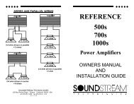
Owner's Manual - Soundstream
Owner's Manual - Soundstream
Owner's Manual - Soundstream

You also want an ePaper? Increase the reach of your titles
YUMPU automatically turns print PDFs into web optimized ePapers that Google loves.
X3.60 / X3.71
TABLE OF CONTENTS<br />
INTRODUCTION 2<br />
FEATURES & SPECIFICATIONS<br />
3 ~ 4<br />
CONTROLS & FUNCTIONS<br />
5 ~ 10<br />
PLANNING & MOUNTING YOUR SYSTEM 11<br />
WIRING DIAGRAM 12<br />
TABLE OF CONTENTS<br />
BRIDGING TWO AMPLIFIERS 13<br />
ADJUSTING & TUNING 14<br />
TROUBLE SHOOTING 15
INTRODUCTION<br />
INTRODUCTION<br />
Amplifier's provide high-performance sound reinforcement for your<br />
mobile audio equipment. The Multi-Mode bridging capabilities allow<br />
flexibility in hosting several different speaker configurations.<br />
To achieve optimum performance, it is highly recommended that you read<br />
this Owners <strong>Manual</strong> before beginning installation.<br />
2
FEATURES<br />
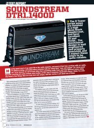
X3.60<br />
Max Power<br />
Damping factor<br />
Operating frequency(band-width)<br />
Input Sensitivity<br />
Low-Pass crossover slope attenuation factor<br />
Subsonic(cut/increase) range factor (15Hz ~ 40Hz)<br />
Continuously variable low-pass control(range)<br />
Continuously variable phase control(range)<br />
Continuously variable bass boost control(range)<br />
Source voltage (Automobile battery)(range)<br />
Maximum DC current 1 Ohm, 1% THD +n<br />
Dimensions(L x W x H)<br />
Test voltage<br />
Platinum RCA connectors<br />
Strap-able; Slave-master relationship<br />
4000Watts<br />
350
CONTROLS & FUNCTIONS<br />
FEATURES<br />
X3.71<br />
Max Power<br />
Damping factor<br />
Operating frequency(band-width)<br />
Input Sensitivity<br />
Low-Pass crossover slope attenuation factor<br />
Subsonic(cut/increase) range factor (15Hz ~ 40Hz)<br />
Continuously variable low-pass control(range)<br />
Continuously variable phase control(range)<br />
Continuously variable bass boost control(range)<br />
Source voltage (Automobile battery)(range)<br />
Maximum DC current 1 Ohm, 1% THD +n<br />
Dimensions(L x W x H)<br />
Test voltage<br />
Platinum RCA connectors<br />
Strap-able; Slave-master relationship<br />
6500Watts<br />
350
10<br />
CONTROLS & FUNCTIONS<br />
Controls & Functions<br />
X3.60<br />
<br />
1 2 8 3 4 7 5 9 6<br />
<br />
14<br />
13<br />
11 12<br />
5
Controls & Functions<br />
X3.71<br />
<br />
CONTROLS & FUNCTIONS<br />
1 2 3 4 5 6 7 8 9 10<br />
<br />
11 13 12<br />
14<br />
6
CONTROLS & FUNCTIONS<br />
Controls & Functions<br />
1.Low Level OUT RCA jacks<br />
L<br />
R<br />
LINE OUT<br />
LINE IN<br />
LINE OUT LINE IN<br />
R<br />
X3.71 L<br />
X3.60<br />
The LINE OUT allows you to build multiple amplifier systems without having to use splitter<br />
cords to distribute the signal. Now it is simply a matter of bringing one set of RCAS into the<br />
first amplifier, then using the line out RCA jacks as the feed to the next amplifier.<br />
2. Low Level Input RCA jacks<br />
L<br />
LINE OUT<br />
LINE IN<br />
LINE OUT LINE IN<br />
R<br />
R<br />
X3.71 L<br />
X3.60<br />
These inputs are for signal cables from the source. Always use high quality shielded RCA<br />
cables.<br />
3. Input Sensitivity Adjustment<br />
LEVEL<br />
Min<br />
Max<br />
This control allows you to vary the amplifier's input sensitivity between 0.5 (500 millivolts) and<br />
10 volts. Clockwise (right-side) rotation raises the threshold and lowers the sensitivity, requiring<br />
higher input signal voltage from the source, in order to obtain maximum output.<br />
Counterclockwise (left-side) adjustment lowers the threshold and raises the sensitivity, requiring<br />
a lower source voltage from the headunit. The overall objective is to set this control to some<br />
intermediate point (0.5 - 10 volts), which closely matches the voltage produced by the headunit.<br />
Avoid setting the threshold too low and supplying excessive input signal voltage, as this would<br />
saturate the input stages and introduce unwanted distortion.<br />
7
Controls & Functions<br />
4.Subsonic Filter Control<br />
SUB<br />
SONIC<br />
Variable Subsonic Filter (15Hz - 40Hz) :<br />
The Subsonic filter will roll off all of the unwanted frequencies below 15Hz - 40Hz.<br />
This will allow the amplifier to use that wasted power on the audible bandwidth.<br />
15Hz<br />
40Hz<br />
CONTROLS & FUNCTIONS<br />
5. Bass Boost Control<br />
BASS<br />
BOOST<br />
0 +18dB<br />
By using the bass boost function, bass notes at 45Hz are emphasized as much as 18dB.<br />
X3.71 X3.60<br />
8
0<br />
CONTROLS & FUNCTIONS<br />
Controls & Functions<br />
7. Low Level Filter Control<br />
50Hz<br />
LOW<br />
PASS<br />
This control is used to set the desired low pass frequency (50 ~ 150HZ).<br />
The filter acts to cut-off frequencies above the set-point. In general, the selected frequency<br />
should closely match the resonant frequency of the speaker box.<br />
150Hz<br />
8. Phase Shift Control<br />
PHASE<br />
SHIFT<br />
0 0<br />
180<br />
The Variable phase control allows you to adjust the relative phase relationship between<br />
your subwoofers and/or your subwoofers & other speakers in your system. This is done by<br />
varying the control between 0 and 180 degrees.<br />
9. Bridged Mode<br />
BRIDGED MODE<br />
SLAVE<br />
MASTER<br />
DATA LINK<br />
69
Controls & Functions<br />
10. LED indicatior<br />
POWER<br />
PROTECTION<br />
POWER : This GREEN LED will illuminate when the amplifier is turned "ON". If it fails to<br />
illuminate, check the power connections to the Amplifier and fuses.<br />
PROTECT: The amplifier protection circuitry will disable the amplifier if input overload, short<br />
circuit or extremely high temperature conditions are detected. When the protection mode<br />
is in operation, the red LED indicator on the side panel will be illuminated, indicating the<br />
amplifier has gone into a self-preservation mode.<br />
CONTROLS & FUNCTIONS<br />
If you observe that the Protection LED is lit, please check the system carefully to determine<br />
what has caused the protection circuit to engage. The amplifier can be reset by turning<br />
the remote power off and then on again. If the amplifier shut down due to a thermal<br />
overload condition, please allow it to cool down before restarting. If the amplifier shut<br />
down because of an input overload or short circuit, be sure to repair these conditions<br />
before attempting to power up the amplifier again.<br />
11. Power(Battery positive)<br />
X3.71 X3.60<br />
Due to the power requirements of the Amplifier, this connection should be made<br />
directly to the positive(+) terminal of battery. For safety measure, install an in-line fuse<br />
-Holder (not included)as close to the battery positive(+) terminal as possible with an<br />
ampere rating not to exceed the maximum current specified on page #3.<br />
10 7
CONTROLS & FUNCTIONS<br />
Controls & Functions<br />
12.B-Terminal (Chassis ground)<br />
X3.71<br />
To avoid unwanted ignition noise caused by ground loops, it is essential that the<br />
Amplifier be grounded to a clean, bare, metal surface of the vehicles chassis.<br />
Note : GROUND WIRE SHOULD NOT BE EXTENDED MORE THAN 3 FT (1 METER).<br />
X3.60D<br />
13. Remote Power On<br />
X3.71<br />
X3.60D<br />
To remote wire From car stereo.<br />
The amplifier is turned "ON" remotely when vehicle's stereo is turned "ON"<br />
Note : IF YOUR RADIO DOES NOT HAVE +12 VOLT OUTPUT LEAD WHEN TURNED ON, THE<br />
"REMOTE" TERMINAL ON THE AMPLIFIER CAN BE CONNECTED TO VEHICLES ACCESSORY<br />
CIRCUIT WHICH PROVIDES +12V WHEN THE CAR IS ON.<br />
14. Speaker Terminals<br />
X3.71<br />
X3.60D<br />
11
Planning and Mounting Your System<br />
The mounting position of your Amplifier will have a great effect on its ability to<br />
dissipate the heat generated during normal operation.<br />
Under normal conditions, the heatsink will dissipate sufficient heat to avoid thermal<br />
shutdown. However please do not install the amplifier in a wooden box or similar<br />
device as this will prevent heat dissipation into the atmosphere.<br />
Temperatures in car trunks have been measured as high as (155'F) in the summer<br />
time. since the thermal shut-down point for the amplifier is (158'F) it is easy to<br />
see that it must be mounted for maximum cooling capability. To achieve<br />
maximum advantage of convection air flow in an enclosed trunk, mount the<br />
amplifier in a horizontal position.<br />
Cooling requirements are considerably relaxed when mounting inside the passenger<br />
compartment since the driver will not often allow temperatures to reach a critical<br />
point. Floor mounting under the seat is usually satisfactory as long as there is at least<br />
1 inch of clearance (2.54 cm) above the Amplifier's fins for ventilation.<br />
A. Select a suitable location that is convenient for mounting, is accessible for wiring.<br />
And has ample room for air circulation and cooling.<br />
B. Use the amplifier as a template to mark the mounting holes. Remove the Amplifier<br />
and drill holes. Use extreme caution, inspect underneath surface before drilling!<br />
C. Secure the Amplifier using the screws provided.<br />
PLANNING & MOUNTING YOUR SYSTEM<br />
12
WIRING DIAGRAM<br />
Wiring Diagram<br />
X3.60<br />
SUB WOOFER<br />
1 OHM<br />
X3.71<br />
SUB WOOFER<br />
1 OHM<br />
13
Bridging Two Amplifiers<br />
X3.60<br />
MASTER AMP<br />
SLAVE AMP<br />
SLAVE<br />
SLAVE<br />
MASTER<br />
MASTER<br />
BRIDGING TWO AMPLIFIERS<br />
MASTER AMP<br />
SPEAKER IMPEDANCE<br />
2 OHMS<br />
SLAVE AMP<br />
14
Bridging Two Amplifiers<br />
BRIDGING TWO AMPLIFIERS<br />
X3.71<br />
MASTER AMP<br />
SLAVE AMP<br />
SLAVE<br />
SLAVE<br />
MASTER<br />
MASTER<br />
MASTER AMP<br />
SPEAKER IMPEDANCE<br />
2 OHMS<br />
SLAVE AMP<br />
15
Tuning on the Amplifier<br />
The amplifier automatically turns on a few seconds after you turn your vehicle's ignition<br />
switch to ACC or ON or turn on your auto sound system, depending on how you wired<br />
the system. The POWER indicator on the top of the amplifier lights when the amplifier is on.<br />
Important : Your amplifier requires 30 amps or more of power from your vehicle's<br />
battery during operation. To protect your battery from discharging,<br />
do not operate the amplifier unless your vehicle is running.<br />
Adjusting The Audio Level<br />
For the best performance, you must set GAIN (MIN / MAX) on the side of the<br />
amplifier to adjust the level of the audio signals that enter the amplifier.<br />
1. Use a screwdriver to turn GAIN (MIN / MAX) fully counterclockwise to MIN.<br />
2. Turn the auto sound system's volume control to about one-third of its full range.<br />
3. Adjust GAIN (MIN / MAX) to a comfortable listening level.<br />
4. Turn up the auto sound system's volume control until the sound begins to distort.<br />
Then immediately turn the volume down to a point just before where the<br />
distortion began.<br />
Caution : Never turn up the auto sound system's volume control more than needed<br />
to adjust the audio level, more than two thirds of its maximum volume.<br />
5. Adjust GAIN (MIN / MAX) until the sound is at the maximum level you want the<br />
amplifier to produce.<br />
6. Adjust the auto sound system's volume control to a comfortable listening level.<br />
ADJUSTING & TUNING<br />
+20dB<br />
FREQUENCY RESPONSE<br />
BASS BOOST ON<br />
RESPONSE (dB)<br />
+10dB<br />
0dB<br />
-10dB<br />
-20dB<br />
35 80<br />
-30dB<br />
10<br />
45<br />
100 500 1K 5K 20K 50K<br />
FREQUENCY (Hz)<br />
NOTE: Raising the Bass frequency allows higher frequencies to reach the bass speakers<br />
while blocking lower frequencies from midrange speakers. Lowering the Bass<br />
frequencies allows lower frequencies to reach the midrange speakers while<br />
blocking higher frequencies from bass speakers.<br />
16
TROUBLE SHOOTING<br />
Trouble Shooting<br />
SYMPTOMS<br />
NO SOUND<br />
Is the power<br />
LED illuminated?<br />
(NO)<br />
CHECK REMEDY<br />
Is the Diagnostic<br />
LED illuminated? (YES)<br />
Check all fuses to amplifier.<br />
Be sure Turn-on lead is connected<br />
Check signal leads.<br />
Check gain control.<br />
Check Tuner/Deck volume level.<br />
Clean contacts on fuse holders.<br />
Check for speaker short or<br />
amplifier overheating.<br />
AMP NOT<br />
SWITCHING<br />
ON<br />
NO SOUND<br />
IN ONE<br />
CHANNEL<br />
AMP TURNING<br />
OFF<br />
MEDIUM /<br />
HIGH<br />
VOLUME<br />
PROTECTION<br />
LAMP ON<br />
No power to power wire<br />
No power to remote<br />
wire with receiver on<br />
Burnt or broken fuse<br />
Check Speaker Leads<br />
Check Audio Leads<br />
Check Speaker load<br />
impedance<br />
Shut down<br />
Speaker wires shorted<br />
Repair power wire or connections.<br />
Check connections to radio.<br />
Replace fuse<br />
Inspect for short circuit or an<br />
open connection.<br />
Reverse Left and Right RCA inputs<br />
to determine if the problem is<br />
occurring before the amp.<br />
Be sure proper speaker load<br />
impedance recommendations<br />
are observed.<br />
(If you use an ohmmeter to check<br />
speaker resistance, please<br />
remember that DC resistance and<br />
AC impedance may not be the same.)<br />
Turn radio down<br />
Wait for AMP to cool<br />
Separate speaker wires and<br />
insulate<br />
17