LM10 linear magnetic encoder system
LM10 linear magnetic encoder system
LM10 linear magnetic encoder system

You also want an ePaper? Increase the reach of your titles
YUMPU automatically turns print PDFs into web optimized ePapers that Google loves.
Data sheet<br />
<strong>LM10</strong>D01_10<br />
Issue 10, 30 th April 2010<br />
®<br />
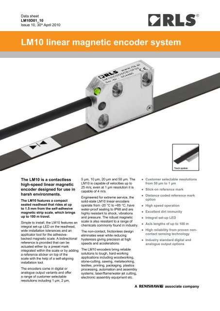
<strong>LM10</strong> <strong>linear</strong> <strong>magnetic</strong> <strong>encoder</strong> <strong>system</strong><br />
Track <strong>system</strong><br />
The <strong>LM10</strong> is a contactless<br />
high-speed <strong>linear</strong> <strong>magnetic</strong><br />
<strong>encoder</strong> designed for use in<br />
harsh environments.<br />
The <strong>LM10</strong> features a compact<br />
sealed readhead that rides at up<br />
to 1.5 mm from the self-adhesive<br />
<strong>magnetic</strong> strip scale, which brings<br />
up to 100 m travel.<br />
Simple to install, the <strong>LM10</strong> features an<br />
integral set-up LED on the readhead,<br />
wide installation tolerances and an<br />
applicator tool for the adhesivebacked<br />
<strong>magnetic</strong> scale. A bidirectional<br />
reference is provided that can be<br />
actuated either by a preset mark<br />
integrated within the scale or by adding<br />
a reference sticker on top of the<br />
scale with the help of a self-aligning<br />
installation tool.<br />
The <strong>encoder</strong>s come in digital or<br />
analogue output variants and offer<br />
a range of customer selectable<br />
resolutions including 1 µm, 2 µm,<br />
5 µm, 10 µm, 20 µm and 50 µm. The<br />
<strong>LM10</strong> is capable of velocities up to<br />
25 m/s; even at 1 µm resolution it is<br />
capable of 4 m/s.<br />
Engineered for extreme service, the<br />
solid-state <strong>LM10</strong> <strong>linear</strong> <strong>encoder</strong>s<br />
operate from -20 °C to +85 °C, have<br />
water-proof sealing to IP68 and are<br />
highly resistant to shock, vibrations<br />
and pressure. The robust <strong>magnetic</strong><br />
scale is also resistant to a range of<br />
chemicals commonly found in industry.<br />
The non-contact, frictionless design<br />
eliminates wear while reducing<br />
hysteresis giving precision at high<br />
speeds and accelerations.<br />
The <strong>LM10</strong> <strong>encoder</strong>s bring reliable<br />
solutions to tough, hard-working<br />
applications including woodworking,<br />
stone-cutting, sawing, metalworking,<br />
textiles, printing, packaging, plastics<br />
processing, automation and assembly<br />
<strong>system</strong>s, laser/flame/water-jet cutting,<br />
electronic assembly equipment etc.<br />
A<br />
●● Customer selectable resolutions<br />
from 50 µm to 1 µm<br />
●● Stick-on reference mark<br />
●● Distance coded reference mark<br />
option<br />
●● High speed operation<br />
●● Excellent dirt immunity<br />
●● Integral set-up LED<br />
●● Axis lengths of up to 100 m<br />
●● High reliability from proven noncontact<br />
sensing technology<br />
●● Industry standard digital and<br />
analogue output options<br />
associate company
Data sheet<br />
<strong>LM10</strong>D01_10<br />
<strong>LM10</strong> dimensions<br />
Dimensions and tolerances in mm.<br />
32<br />
3<br />
R20min dynamic<br />
D<br />
13.5<br />
Ø4.2<br />
4min<br />
reference mark sensor designator<br />
28.5<br />
20.5<br />
5.7<br />
19<br />
sensor position<br />
3.3<br />
3.5<br />
2<br />
4<br />
18.5<br />
2<br />
24<br />
H<br />
reference mark sensor designator<br />
2.1<br />
10<br />
5.3<br />
2.1<br />
3<br />
10 ±0.2<br />
7.7<br />
No cover foil, cut or<br />
magnetised reference mark<br />
No cover foil, stick-on<br />
reference mark<br />
With cover foil, cut or<br />
magnetised reference mark<br />
With cover foil, stick-on<br />
reference mark<br />
Magnetic scale<br />
thickness (D)<br />
Maximum range<br />
Ride height (H)<br />
Recommended range<br />
1.5 -0.2 0.1 - 1.5 0.1 - 1.0<br />
1.5 -0.2 0.5 - 1.5 0.5 - 1.0<br />
1.65 -0.2 0.1 - 1.3 0.1 - 0.9<br />
1.65 -0.2 0.5 - 1.3 0.5 - 0.9<br />
<strong>LM10</strong> installation tolerances<br />
Ride height<br />
Lateral offset<br />
H<br />
±3°<br />
Pitch<br />
±1.0<br />
Roll<br />
±3°<br />
Yaw<br />
±1°<br />
2
®<br />
<strong>LM10</strong> technical specifications<br />
System data<br />
Maximum measuring length<br />
Pole length<br />
50 m (100 m special order)<br />
2 mm<br />
Available resolution for digital outputs 1 µm, 2 µm, 5 µm, 10 µm, 20 µm and 50 µm<br />
Sinusoidal period length<br />
2 mm<br />
Maximum speed<br />
For analogue voltage and analogue current output: 25 m/s<br />
For digital output signals:<br />
Resolution<br />
(µm)<br />
Maximum velocity<br />
(m/s)<br />
1 4.16 1.04 0.52 0.26 0.13<br />
2 8.32 2.08 1.04 0.52 0.25<br />
5 20.80 5.20 2.59 1.30 0.63<br />
10 25.00 10.40 5.20 2.59 1.27<br />
20 25.00 10.40 5.20 2.59 1.27<br />
50 25.00 6.50 3.25 1.62 0.79<br />
Edge separation (μs) 0.12 0.50 1 2 4<br />
Count frequency (kHz) 8333 2000 1000 500 250<br />
Precision class<br />
±40 µm/m<br />
Linear expansion coefficient ~ 17 × 10 -6 /K<br />
Repeatability<br />
Better than unit of resolution for movement in the same direction<br />
Hysteresis*<br />
< 3 µm up to 0.2 mm ride height<br />
Sub divisional error ±3.5 µm for < 0.7 mm ride height (to ensure SDE remains under ±3.5 µm order option 01 that<br />
±7.5 µm for 1 mm ride height<br />
±15 µm for 1.5 mm ride height<br />
provides alarm and red LED at 0.7 mm ride height)<br />
Electrical data<br />
Power supply<br />
4.7 V to 7 V – reverse polarity protected; voltage on readhead<br />
Power consumption (without any load) < 35 mA for digital output type<br />
< 50 mA for analogue output types<br />
Voltage drop over cable<br />
13 mV/m – without load<br />
54 mV/m – with 120 Ω load<br />
Output signals<br />
Digital – Open Collector NPN, Differential RS422, short circuit protected<br />
Analogue – Differential 1 V pp<br />
, 12 µA<br />
Mechanical data<br />
Cable<br />
PUR high flexible cable, drag-chain compatible, double-shielded<br />
8 × 0.05 mm 2 ; durability: 20 million cycles at 20 mm bend radius<br />
Mass<br />
Readhead (1 m cable, no connector) 56.4 g, Magnetic scale (1 m) 60 g, Cover foil (1 m) 3.5 g<br />
Environmental conditions<br />
Temperature Operating -10 °C to +80 °C (cable under non-dynamic conditions: -20 °C to +85 °C)<br />
Storage -40 °C to +85 °C<br />
Environmental sealing IP68 (according to IEC 60529)<br />
EMC Immunity<br />
IEC 61000-6-2 (particularly: ESD: IEC 61000-4-2; EM fields: IEC 61000-4-3; Burst: IEC 61000-4-4; Surge:<br />
IEC 61000-4-5; Conducted disturbances: IEC 61000-4-6; Power frequency magnet fields: IEC 61000-4-8;<br />
Pulse <strong>magnetic</strong> fields: IEC 61000-4-9)<br />
EMC Interference IEC 61000-6-4 (for industrial, scientific and medical equipment: IEC 55011)<br />
Vibrations (55 Hz to 2000 Hz) 300 m/s 2 (IEC 60068-2-6)<br />
Shocks (11 ms) 300 m/s 2 (IEC 60068-2-27)<br />
* Repeatable, and can be measured and compensated once installed<br />
A<br />
associate company<br />
3
Data sheet<br />
<strong>LM10</strong>D01_10<br />
<strong>LM10</strong>IB – Digital output signals, Open Collector NPN<br />
Square wave output<br />
Power supply<br />
voltage<br />
Power<br />
consumption<br />
Output signals<br />
Reference signal<br />
Maximum load<br />
Cable<br />
5 V to 30 V<br />
< 35 mA<br />
A, B, Z<br />
1 or more square-wave pulses Z<br />
10 mA<br />
max. 10 m<br />
Timing diagram<br />
A<br />
B<br />
Z<br />
Edge separation (µs)<br />
Resolution (µm)<br />
Recommended signal termination<br />
Vcc = 5 V - 30 V<br />
Vcc = 5 V - 30 V<br />
R L<br />
A, B, Z<br />
Readhead<br />
0 V<br />
Customer electronics<br />
NOTE: Set-up LED in the case of poor signal strength is flashing red.<br />
V CC<br />
R L min<br />
5 500<br />
12 1,200<br />
24 2,400<br />
30 3,000<br />
<strong>LM10</strong>IC – Digital output signals, RS422<br />
Square wave differential line driver to EIA RS422<br />
Power supply<br />
voltage<br />
Output signals<br />
Reference signal<br />
Signal level<br />
Permissible load<br />
4.7 V to 7 V – reverse polarity protected;<br />
voltage on readhead *<br />
Reverse polarity protection<br />
2 square-wave signals A, B and their<br />
inverted signals A-, B-<br />
1 or more square-wave pulse Z and its<br />
inverted pulse Z-<br />
Differential line driver to EIA standard<br />
RS422:<br />
U H ≥ 2.5 V at -I H = 20 mA<br />
U L ≤ 0.5 V at I L = 20 mA<br />
Z 0 ≥ 100 Ω between associated outputs<br />
I L ≤ 20 mA max. load per output<br />
Capacitive load ≤ 1000 pF<br />
Outputs are protected against short circuit<br />
to 0 V and to +5 V<br />
Alarm High impedance on output lines A, B, A-, B-<br />
Switching time<br />
(10 to 90 %)<br />
Cable length<br />
* Please consider voltage drop over cable.<br />
t+, t- < 30 ns (with 1 m cable and<br />
recommended input circuit)<br />
max. 100 m<br />
Timing diagram<br />
Complementary signals not shown<br />
A<br />
B<br />
Z<br />
Recommended signal termination<br />
Readhead<br />
A B Z +<br />
A B Z -<br />
Cable Z 0<br />
= 120R<br />
Edge separation (µs)<br />
Resolution (µm)<br />
120R<br />
Customer<br />
electronics<br />
4
®<br />
<strong>LM10</strong>AV – Analogue output signals (1 V pp<br />
)<br />
2 channels V 1<br />
and V 2<br />
differential sinusoidals (90° phase shifted)<br />
Power supply<br />
voltage<br />
Incremental<br />
signals<br />
Reference signal<br />
Termination<br />
Cable length<br />
4.7 V to 7 V – reverse polarity protected;<br />
voltage on readhead *<br />
Reverse polarity protection<br />
Amplitude<br />
0.6 V pp<br />
to 1.2 V pp<br />
(with 120 Ω termination)<br />
Phase shift 90° ± 0.5°<br />
Amplitude<br />
0.8 V pp<br />
to 1.2 V pp<br />
(with 120 Ω termination)<br />
Position 45°<br />
Width 22.5°<br />
Z 0 = 120 Ω between associated outputs<br />
max. 50 m<br />
Timing diagram<br />
(V 1<br />
+) - (V 1<br />
-)<br />
0 V<br />
(V 2<br />
+) - (V 2<br />
-)<br />
0 V<br />
45°<br />
360°<br />
0.6 V pp<br />
- 1.2 V pp<br />
with 120 Ω<br />
termination<br />
* Please consider voltage drop over cable.<br />
(V 0<br />
+) - (V 0<br />
-)<br />
0 V<br />
0.8 V pp<br />
- 1.2 V pp<br />
with 120 Ω<br />
termination<br />
22.5°<br />
<strong>LM10</strong>AC – Analogue micro current output signals (12 µA)<br />
2 channels I 1<br />
and I 2<br />
sinusoidals (90° phase shifted)<br />
Power supply<br />
voltage<br />
Incremental<br />
signals<br />
4.7 V to 7 V – reverse polarity protected;<br />
voltage on readhead *<br />
Reverse polarity protection<br />
Amplitude 7 µA to 16 µA<br />
Phase shift 90° ± 0.5°<br />
Reference signal Amplitude 8 µA to 12 µA<br />
Position 45°<br />
Width 22.5°<br />
Cable length max. 10 m<br />
Timing diagram<br />
I 1<br />
0 µA<br />
I 2<br />
45°<br />
360°<br />
7 µA - 16 µA<br />
* Please consider voltage drop over cable.<br />
0 µA<br />
I 0<br />
0 µA<br />
8 µA - 12 µA<br />
22.5°<br />
A<br />
associate company<br />
5
Data sheet<br />
<strong>LM10</strong>D01_10<br />
Reference mark<br />
The repeatable bi-directional reference signal can be provided in 4 ways.<br />
1) Stick-on reference mark. The <strong>LM10</strong> readhead should be ordered with the reference mark option. After installation<br />
of the scale a reference mark sticker can be applied to the scale at the required position using the reference mark<br />
applicator tool. Ensure that the reference sticker is oriented to the corresponding side of the readhead that has the<br />
reference mark designator marked.<br />
Reference mark<br />
designator<br />
2) Selected at point of order. The <strong>LM10</strong> readhead should be ordered with the reference mark option. If required, the<br />
cover foil can be installed over the cut reference mark.<br />
NOTE: The shape of the cut and position is critical so<br />
this option is only available as factory order.<br />
Cut reference mark<br />
3) Every 2 mm. The <strong>LM10</strong> readhead should be ordered with this specific mode activated only.<br />
4) Distance coded reference mark. The distance coded reference mark option provides multiple reference marks that<br />
are individually spaced according to specific mathematical algorithm. Absolute position is calculated after traversing<br />
2 succesive reference marks. Maximum length and minimal traverse depend on basic spacing (K) between reference<br />
marks, which is customer selectable at point of order. For further information please refer to Distance coded reference<br />
mark data sheet (<strong>LM10</strong>D17).<br />
K<br />
K<br />
MS10/WWYYBB-2000-NNN<br />
K/2<br />
K/2 + P<br />
K/2 - P K/2 +2P K/2 - 2P K/2 + 3P<br />
K + P<br />
K + P<br />
3P<br />
K - 2P K/2<br />
K + P<br />
L max<br />
Set-up LED<br />
After the installation of the <strong>magnetic</strong> scale (see <strong>LM10</strong> Installation guide) the readhead can be easily adjusted on the<br />
machine using the set-up LED indicator.<br />
Green LED = good signal strength / set-up<br />
Programming<br />
Red LED = poor signal strength – adjustment required<br />
A, B, A-, B- outputs become high impedance<br />
NOTE: IB output type: LED flashes red.<br />
Readheads can be ordered preset to the required resolution or provided so that they can be programmed as needed on<br />
the machine to the chosen resolution. This programming is carried out by connecting the readhead to a computer via a<br />
programming interface. Programming option is available for IC output only.<br />
Positive direction<br />
Digital output signals – A leads B<br />
Analogue output signals (1 V pp<br />
) – V 1<br />
leads V 2<br />
6<br />
Analogue output signals (12 µA) – I 1<br />
leads I 2
Data sheet<br />
<strong>LM10</strong>D01_10<br />
<strong>LM10</strong> readhead part numbering<br />
<strong>LM10</strong> <strong>system</strong> = Readhead + Scale<br />
Readhead part number<br />
eg <strong>LM10</strong>IC010CA10F00<br />
Magnetic scale part number<br />
eg MS10B1000B0032<br />
<strong>LM10</strong> IC 010 C A 10 F 00<br />
Output type<br />
IB - Incremental, Open Collector NPN; 5 V - 30 V<br />
IC - Incremental, RS422; 5 V<br />
AV - Analogue voltage, 1 V pp ; 5 V<br />
AC - Analogue micro current, 12 µA; 5 V<br />
Resolution<br />
000 - for AV and AC output types<br />
For IB and IC output types<br />
001 - 1 µm<br />
002 - 2 µm<br />
005 - 5 µm<br />
010 - 10 µm<br />
020 - 20 µm<br />
050 - 50 µm<br />
PRG - Programmable from 1 µm to 50 µm - preset to 1 µm<br />
(for IC output type)<br />
Minimum edge separation<br />
For AV and AC output types<br />
A - N/A<br />
Special requirements<br />
00 - No special requirements (standard)<br />
01 - 0.7 mm ride height alarm<br />
Connector option<br />
A - 9 pin D type plug (for IC output type)<br />
D - 15 pin D type plug (for IC output type)<br />
L - 15 pin D type plug (for AV output type)<br />
H - 15 pin HD type plug<br />
P - 9 pin D type plug (for AV output type)<br />
F - Flying lead (no connector)<br />
Cable length<br />
10 - 1.0 m (standard)<br />
Reference<br />
A - With reference<br />
B - No reference<br />
C - Periodic as per scale pitch (2 mm)<br />
For IB and IC output types<br />
A - 0.12 µs (8.3 MHz)*<br />
B - 0.5 µs (2 MHz)<br />
C - 1 µs (1 MHz)<br />
D - 2 µs (0.5 MHz)<br />
E - 4 µs (0.25 MHz)<br />
* Default for PRG option.<br />
7
®<br />
Magnetic scale part numbering<br />
Hole to hole distance 1<br />
Scale length<br />
Ends<br />
prepared for<br />
end clamping<br />
(option C)<br />
Measuring length 2<br />
Positive counting<br />
3 ±0.5 End clamp<br />
3.5 ±0.5<br />
10 ±0.2<br />
End clamp<br />
10<br />
Min. distance<br />
of Ri from<br />
left edge<br />
Position of reference mark<br />
MS10B/WWYYBB-2000-NNN<br />
Cut or magnetised<br />
reference mark (Ri)<br />
10<br />
Min. distance<br />
of Ri from<br />
right edge<br />
1<br />
Hole to hole distance = scale length + 6 ±1 mm (for end clamp mounting)<br />
2<br />
Measuring length = scale length - 17 mm<br />
MS10 B 1000 B 0032<br />
Precision class<br />
B - ±40 µm/m<br />
Scale length<br />
xxxx - Where xxxx equals scale length in cm<br />
Reference mark<br />
0000 - No reference mark<br />
xxxx - Where xxxx equals position of machined reference<br />
mark in cm (reference mark position will be within<br />
±1 cm from requested position)<br />
Dxxx - Distance coded reference mark; where xxx equals<br />
basic increment in mm<br />
Options<br />
A - No cover foil<br />
B - Cover foil supplied (separately - 5 cm longer than tape)<br />
C - No cover foil, ends prepared for end clamping<br />
G - Track <strong>system</strong> *<br />
* For details on TRS track <strong>system</strong> please refer to<br />
data sheet <strong>LM10</strong>D18<br />
Accessories part numbering<br />
Cover foil<br />
CF10 1000<br />
Foil length<br />
xxxx - Where xxxx equals foil length in cm<br />
Stick-on reference mark<br />
Applicator tool for stick-on reference mark<br />
Applicator tool for <strong>magnetic</strong> scale and cover foil<br />
End clamp kit (2 clamps + 2 screws)<br />
Reference mark magnetiser<br />
<strong>LM10</strong>SRM00<br />
<strong>LM10</strong>ARM00<br />
<strong>LM10</strong>ASC00<br />
<strong>LM10</strong>ECL00<br />
<strong>LM10</strong>CRM00<br />
A<br />
associate company<br />
8
®<br />
Head office<br />
RLS merilna tehnika d.o.o.<br />
Cesta II. grupe odredov 25<br />
SI-1261 Ljubljana - Dobrunje<br />
Slovenia<br />
T +386 1 5272100<br />
F +386 1 5272129<br />
E mail@rls.si<br />
www.rls.si<br />
is our worldwide sales support partner for Magnetic Encoders.<br />
Australia<br />
T +61 3 9521 0922<br />
E australia@renishaw.com<br />
Germany<br />
T +49 7127 9810<br />
E germany@renishaw.com<br />
The Netherlands<br />
T +31 76 543 11 00<br />
E benelux@renishaw.com<br />
Sweden<br />
T +46 8 584 90 880<br />
E sweden@renishaw.com<br />
Austria<br />
T +43 2236 379790<br />
E austria@renishaw.com<br />
Hong Kong<br />
T +852 2753 0638<br />
E hongkong@renishaw.com<br />
Poland<br />
T +48 22 577 11 80<br />
E poland@renishaw.com<br />
Switzerland<br />
T +41 55 415 50 60<br />
E switzerland@renishaw.com<br />
Brazil<br />
T +55 11 4195 2866<br />
E brazil@renishaw.com<br />
Hungary<br />
T +36 23 502 183<br />
E hungary@renishaw.com<br />
Russia<br />
T +7 495 231 1677<br />
E russia@renishaw.com<br />
Taiwan<br />
T +886 4 2473 3177<br />
E taiwan@renishaw.com<br />
Canada<br />
T +1 905 828 0104<br />
E canada@renishaw.com<br />
India<br />
T +91 20 6674 6751<br />
E india@renishaw.com<br />
Singapore<br />
T +65 6897 5466<br />
E singapore@renishaw.com<br />
UK<br />
T +44 1453 524524<br />
E uk@renishaw.com<br />
The People’s Republic of China<br />
T +86 10 8448 5306<br />
E beijing@renishaw.com<br />
Israel<br />
T +972 4 953 6595<br />
E israel@renishaw.com<br />
Slovenia<br />
T +386 1 52 72 100<br />
E mail@rls.si<br />
USA<br />
T +1 847 286 9953<br />
E usa@renishaw.com<br />
Czech Republic<br />
T +420 5 4821 6553<br />
E czech@renishaw.com<br />
France<br />
T +33 1 64 61 84 84<br />
E france@renishaw.com<br />
Italy<br />
T +39 011 966 10 52<br />
E italy@renishaw.com<br />
Japan<br />
T +81 3 5366 5316<br />
E japan@renishaw.com<br />
South Korea<br />
T +82 2 2108 2830<br />
E southkorea@renishaw.com<br />
Spain<br />
T +34 93 663 34 20<br />
E spain@renishaw.com<br />
For all other countries<br />
Please contact RLS’ head<br />
office<br />
T +386 1 52 72 100<br />
E mail@rls.si<br />
RLS d.o.o. has made considerable effort to ensure the content of this document is correct at the date of publication but makes no warranties or<br />
representations regarding the content. RLS d.o.o. excludes liability, howsoever arising, for any inaccuracies in this document. © 2010 RLS d.o.o.
®<br />
Document issues<br />
Issue Date Page Corrections made<br />
01 8. 11. 2007 - New document<br />
02 29.11.2007 - Minor text errors corrected, Corrected Maximum speed table data on page 3<br />
30.11.2007 2 Changed Pitch and Yaw description and image layout<br />
15. 1. 2008 3, 4, 5 Minor text errors corrected<br />
03 28. 2. 2008 1, 3, 7 Removed the 100 µm option<br />
2 Added the Reference mark detection side symbol<br />
5 New reference mark images<br />
8 Added the <strong>magnetic</strong> scale dimensions image<br />
04 6. 6. 2008 2, 5 New installation drawing<br />
- Reference mark installation moved to <strong>LM10</strong> Installation guide<br />
4, 6 Analogue output signal specifications added<br />
6 IB output type removed, AC output type and connector option L added<br />
05 25. 11. 2008 4, 7, 8 IB output type, new <strong>magnetic</strong> scale diagram and end clamping option added<br />
06 5. 12. 2008 3 Hysteresis data added<br />
07 14. 1. 2009 - New layout<br />
08 29. 7. 2009 5 Amended reference signal width for 1 V pp<br />
output variant<br />
09 4. 8. 2009 5 Amended reference signal width for 12 µA output variant<br />
10 30. 4. 2010 2 Ride height table added, lateral offset and yaw updated<br />
6 Distance coded reference mark option added<br />
8 End clamp option added to technical drawing; distance coded reference mark and track section option added; reference mark<br />
magnetiser added to accessories