MS magnetic scale installation guide for LM10 ... - Resource Centre
MS magnetic scale installation guide for LM10 ... - Resource Centre
MS magnetic scale installation guide for LM10 ... - Resource Centre

You also want an ePaper? Increase the reach of your titles
YUMPU automatically turns print PDFs into web optimized ePapers that Google loves.
Installation <strong>guide</strong><br />
<strong>LM10</strong>D02_05<br />
Issue 5, 22 nd January 2010<br />
®<br />
<strong>MS</strong> <strong>magnetic</strong> <strong>scale</strong> <strong>installation</strong> <strong>guide</strong><br />
<strong>for</strong> <strong>LM10</strong> and LM15 readheads<br />
EMC compliance<br />
The <strong>LM10</strong> and LM15 encoder systems con<strong>for</strong>m to the relevant harmonised<br />
European standards <strong>for</strong> electro<strong>magnetic</strong> compatibility as detailed below.<br />
BS EN 61326<br />
Patents<br />
Features of RLS’s encoder systems and similar products are the subjects of the<br />
following patents and patent applications:<br />
GB 0720972.9 EP 0514081<br />
EP 0388453 US 5,241,173<br />
US 5,063,685 JP 3,202,316<br />
JP 2837483<br />
Further in<strong>for</strong>mation<br />
For further in<strong>for</strong>mation relating to the <strong>installation</strong> of <strong>LM10</strong> or LM15 encoder<br />
systems, see also the <strong>LM10</strong> or LM15 Data sheet (part no. <strong>LM10</strong>D01 and<br />
LM15D01) and the <strong>LM10</strong> or LM15 <strong>installation</strong> <strong>guide</strong> (part no. <strong>LM10</strong>D06 and<br />
LM15D02). These can be downloaded from www.rls.si.<br />
Disclaimer<br />
Considerable ef<strong>for</strong>t has been made to ensure that the contents of this document<br />
are free from inaccuracies and omissions. However, RLS merilna tehnika d.o.o.<br />
makes no warranties with respect to the contents of this document and specifically<br />
disclaims any implied warranties. RLS merilna tehnika d.o.o. reserves the right<br />
to make changes to this document and to the product described herein without<br />
obligation to notify any person of such changes.<br />
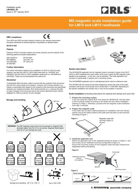
System description<br />
The <strong>LM10</strong>ASC00 applicator tool <strong>for</strong> <strong>magnetic</strong> <strong>scale</strong> is mounted in place of any RLS ®<br />
<strong>LM10</strong> or LM15 readhead and uses motion of the axis to apply the <strong>MS</strong> <strong>magnetic</strong> <strong>scale</strong><br />
parallel to the <strong>guide</strong>way – a one man, one hit operation. The <strong>scale</strong> applicator tool<br />
consists of a <strong>guide</strong> plate, 2 spacers and 2 mounting screws.<br />
The <strong>LM10</strong>ARM00 applicator tool is a self-aligning tool <strong>for</strong> stick-on reference mark.<br />
The <strong>LM10</strong>ECL00 end clamp kit has been designed to anchor the ends of the <strong>scale</strong>.<br />
Included in the kit are 2 end clamps and 2 screws M2.5 × 6 DIN 965. Depending on<br />
the specific <strong>installation</strong> end clamps may or may not be suitable or required.<br />
Scale <strong>installation</strong> (including instructions <strong>for</strong> optional end clamps and cover foil)<br />
Storage and handling<br />
> 60 mm<br />
1. Prepare the mounting surface<br />
If you are using the original RLS ® end clamp kit <strong>LM10</strong>ECL00, drill the holes<br />
to the mounting surface according to the Scale and end clamp <strong>installation</strong><br />
drawing on Page 2. Otherwise, proceed with the <strong>magnetic</strong> <strong>scale</strong> <strong>installation</strong><br />
from step 3 onwards.<br />
2. Prepare the <strong>magnetic</strong> <strong>scale</strong><br />
If the <strong>scale</strong> has not been ordered prepared <strong>for</strong> <strong>installation</strong> with end clamps,<br />
please ensure the rubber surface of the <strong>scale</strong> ends has been cut and removed<br />
according to Figure 1.<br />
Figure 1<br />
Magnetic <strong>scale</strong> with<br />
removed rubber on<br />
the end<br />
WARNING: The <strong>MS</strong> <strong>magnetic</strong> <strong>scale</strong> should not be exposed to <strong>magnetic</strong> field<br />
densities higher than 50 mT on its surface. Magnetic fields higher<br />
than 50 mT can damage the <strong>scale</strong>.<br />
3.5 ±0.5 mm<br />
Motor oil<br />
Brake fluid<br />
Turpentine<br />
Heptane<br />
Benzene<br />
Toluene<br />
Alcohol<br />
3. Install the applicator tool<br />
Mount the applicator tool to the readhead bracket as shown in Figure 2. Use<br />
two screws as per readhead mounting configuration (Figure 3).<br />
Ensure the mounting surface <strong>for</strong> the <strong>magnetic</strong> <strong>scale</strong> has been cleaned and<br />
degreased be<strong>for</strong>e proceeding.<br />
Figure 2<br />
Guide plate<br />
Kerosene<br />
Antifreeze<br />
Ketone H 2<br />
SO 4<br />
HCl<br />
Readhead mounting<br />
bracket<br />
(not supplied)<br />
A<br />
A<br />
Figure 3<br />
Screw mounting<br />
Spacers<br />
Mounting screws<br />
Option 1 Option 2<br />
Storage and operating -40 °C to +120 °C<br />
Up to 100 % RH<br />
A<br />
associate company
Installation <strong>guide</strong><br />
<strong>LM10</strong>D02_05<br />
Scale and end clamp <strong>installation</strong> drawing<br />
Hole to hole distance 1<br />
Scale length<br />
Measuring length 2<br />
3.5 ±0.5<br />
Positive counting<br />
10 ±0.2<br />
End clamp<br />
10<br />
Min. distance<br />
of Ri from<br />
left edge<br />
Position of reference mark<br />
<strong>MS</strong>10B/WWYYBB-2000<br />
Cut or magnetised<br />
reference mark (Ri)<br />
3 ±0.5 End clamp<br />
10<br />
Min. distance<br />
of Ri from<br />
right edge<br />
Hole <strong>for</strong> M2.5 × 6<br />
screws<br />
End clamp<br />
1.5 ±0.2<br />
6<br />
Mounting<br />
surface<br />
3.5 ±0.5<br />
Scale length<br />
1<br />
Hole to hole distance = <strong>scale</strong> length + 6 ±1 mm<br />
2<br />
Measuring length = <strong>scale</strong> length - 17 mm<br />
4. Load the <strong>scale</strong> into the applicator tool<br />
Separate the backing paper from the first 40 mm of <strong>scale</strong> and feed it into<br />
the applicator tool.<br />
Push the <strong>scale</strong> carefully through to the end of <strong>scale</strong> mark, ensuring that<br />
it does not stick to the mounting surface until it is in position.<br />
10. Apply the stick-on reference mark (if used)<br />
Place the <strong>LM10</strong>ARM00 reference mark applicator tool on <strong>scale</strong> in the correct<br />
orientation/required position along the length (Figure 5).<br />
Figure 5<br />
NOTE: To prevent the <strong>scale</strong> sticking to the mounting surface during this<br />
operation it may be necessary to re-apply approximately 20 mm<br />
of backing paper to the end of the <strong>scale</strong> be<strong>for</strong>e inserting through<br />
<strong>scale</strong> <strong>guide</strong>.<br />
Self-aligning<br />
reference mark<br />
applicator tool<br />
Magnetic <strong>scale</strong><br />
Attach the end of the <strong>scale</strong> to the mounting surface with light finger<br />
pressure.<br />
5. Apply the <strong>scale</strong><br />
Traverse the axis through its full travel at a slow, steady speed.While<br />
moving the axis:<br />
●● Apply a light finger pressure to the <strong>scale</strong> behind the applicator tool<br />
to attach it to the mounting surface.<br />
●● Gently pull the backing paper away from in front of the applicator<br />
tool as it is separated.<br />
6. Remove the applicator tool<br />
When the applicator tool has reached the limit of its travel, lock it in place<br />
and unbolt it from the readhead mounting bracket.<br />
7. Ensure complete adhesion<br />
Apply firm finger pressure along the full length of the <strong>scale</strong> from the<br />
centre outwards to each end.<br />
8. Install the end clamps (if used)<br />
Use the enclosed screws and screw the end clamps ensuring the end of<br />
<strong>magnetic</strong> <strong>scale</strong> is held under the clamp (Figure 4).<br />
11. Stick the reference mark on the <strong>scale</strong><br />
Remove the backing tape from the reference mark sticker and carefully attach it to<br />
the surface of the <strong>scale</strong> by placing it next to the applicator tool (Figure 6).<br />
NOTE: The correct orientation of reference mark is crucial. The mark on the<br />
sticker should be on the same side as the reference mark designators.<br />
Figure 6<br />
Reference mark<br />
designator<br />
Reference<br />
mark sticker<br />
Figure 4<br />
Ø2.6<br />
12. Remove the stick-on reference mark applicator tool<br />
Remove the applicator tool leaving the reference mark sticker in the desired<br />
position (Figure 7).<br />
3.5 ±0.5<br />
Figure 7<br />
10<br />
9. Apply cover foil (if used)<br />
Degrease the <strong>scale</strong> surface with alcohol and install as per <strong>scale</strong><br />
<strong>installation</strong> instructions in step 3 onwards.<br />
DO NOT remove the <strong>scale</strong> <strong>for</strong> refitting or use elsewhere once it has been<br />
applied to the mounting surface. The <strong>scale</strong> can be applied once only.