Cage instability of XMM-Newton's reaction wheels ... - SpaceOps 2012
Cage instability of XMM-Newton's reaction wheels ... - SpaceOps 2012
Cage instability of XMM-Newton's reaction wheels ... - SpaceOps 2012

You also want an ePaper? Increase the reach of your titles
YUMPU automatically turns print PDFs into web optimized ePapers that Google loves.
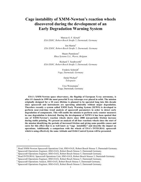
<strong>Cage</strong> <strong>instability</strong> <strong>of</strong> <strong>XMM</strong>-Newton’s <strong>reaction</strong> <strong>wheels</strong><br />
discovered during the development <strong>of</strong> an<br />
Early Degradation Warning System<br />
Marcus G. F. Kirsch 1<br />
ESA ESOC, Robert-Bosch Straße 5, Darmstadt, Germany<br />
Jim Martin 2<br />
ESA ESOC, Robert-Bosch Straße 5, Darmstadt, Germany<br />
Mauro Pantaleoni 3<br />
Rhea Systems S.A., Wavre, Belgium<br />
Richard T. Southworth 4<br />
ESA ESOC, Robert-Bosch Straße 5, Darmstadt, Germany<br />
Frederic Schmidt 5<br />
Vega, Darmstadt, Germany<br />
Detlef Webert 6<br />
Telespazio<br />
Uwe Weissmann 7<br />
Vega, Darmstadt, Germany<br />
ESA’s <strong>XMM</strong>-Newton space observatory, the flagship <strong>of</strong> European X-ray astronomy, is<br />
after it’s launch in 1999 the most powerful X-ray telescope ever placed in orbit. The mission<br />
originally designed for a 10 years lifetime is planned to be operated long into this decade<br />
since spacecraft and instruments are operating admirably without major degradation.<br />
Therefore recently a system called <strong>XMM</strong> Early Warning System (XEWS) is developed to<br />
perform near-real-time trend analysis <strong>of</strong> spacecraft parameters in order to detect early<br />
degradation <strong>of</strong> components. This will enable the mission to perform early counter measures<br />
in case degradation is detected. During the development <strong>of</strong> XEWS it has been spotted that<br />
one <strong>of</strong> <strong>XMM</strong>-Newton’s <strong>reaction</strong> <strong>wheels</strong> shows since 2008 non-periodic friction increase<br />
during stable pointing. We present an analysis <strong>of</strong> all four <strong>reaction</strong>s <strong>wheels</strong> since the start <strong>of</strong><br />
the mission identifying the periods <strong>of</strong> increased friction and giving some possible causes and<br />
cures for this effect that is as well know as “cage <strong>instability</strong>” and describe the impact on<br />
operations. Additionally a comparison with the <strong>wheels</strong> <strong>of</strong> ESA’s INTEGRAL spacecraft<br />
which is using effectively the same Attitude and Orbit Control System will be presented.<br />
.<br />
1 Head <strong>XMM</strong>-Newton Spacecraft Operations Unit, HSO-OAX, Robert Bosch Strasse 5, Darmstadt Germany.<br />
2 Spacecraft Operations Engineer, HSO-OAX, Robert Bosch Strasse 5, Darmstadt Germany.<br />
3 Spacecraft Operations Engineer, HSO-OAX, Robert Bosch Strasse 5, Darmstadt Germany.<br />
4 Head INTEGRAL Spacecraft Operations Unit, HSO-OAX, Robert Bosch Strasse 5, Darmstadt Germany.<br />
5 Spacecraft Operations Engineer, HSO-OAX, Robert Bosch Strasse 5, Darmstadt Germany.<br />
6 Spacecraft Operations Analyst, HSO-OAX, Robert Bosch Strasse 5, Darmstadt Germany.<br />
7 Spacecraft Operations Engineer, HSO-OAX, Robert Bosch Strasse 5, Darmstadt Germany.<br />
1
E<br />
I. ESAs high energy astrophysical observatories <strong>XMM</strong>-Newton and INTEGRAL<br />
SA is operating within it’s Horizon 2000 programme two major astrophysical observatories in the high energy<br />
regime <strong>of</strong> X- and Gamma-rays. The goal <strong>of</strong> these missions is to unveil the hot and violent universe with an<br />
unprecedented accuracy in terms <strong>of</strong> spectral and imaging detection capabilities. Both missions have originally been<br />
planned for a mission lifetime <strong>of</strong> less than a decade but operate still without major degradation and are facing a very<br />
high scientific demand. 1)<br />
<strong>XMM</strong>-Newton 2) was launched in December 1999 on the Ariane 504 rocket from French Guyana. As a corner<br />
stone mission <strong>of</strong> Horizon 2000 it observes the hot X-ray universe with objects like neutron stars, black holes or<br />
active galaxies and has the largest X-ray collecting area <strong>of</strong> an X-ray observatory ever launched. The three-axis<br />
stabilized and 3.8 tons heavy spacecraft with a pointing accuracy <strong>of</strong> one arcsec consists <strong>of</strong> three main sections: A<br />
seven meter long telescope tube, a squarish service module also carrying three telescopes at its forward broader end<br />
and the focal plane assembly housing the detectors at its other extremity. Its pair <strong>of</strong> solar panels has a 16-metre<br />
span. <strong>XMM</strong>-Newton was ingested in to a highly elliptical orbit with a perigee around 20.000 km and an Apogee <strong>of</strong><br />
120000 km and a southern inclination <strong>of</strong> 40 deg. This highly eccentric orbit has been chosen for two reasons. First,<br />
the <strong>XMM</strong>-Newton instruments need to work outside the radiation belts surrounding the Earth. Second, a highly<br />
eccentric orbit <strong>of</strong>fers the longest possible observation periods - less interrupted by the frequent passages in the<br />
Earth's shadow that occur in a low orbit. In addition, the orbital period <strong>of</strong> <strong>XMM</strong>-Newton is exactly two times the<br />
Earth rotation period to maintain optimal contact between <strong>XMM</strong>-Newton and the ground stations tracking the<br />
satellite. This allows <strong>XMM</strong>-Newton data to be received in real-time and for it to be fed to the Mission Control<br />
Centres. Note that <strong>XMM</strong>-Newton has no onboard data storage capacity, so all data is immediately down-linked to<br />
the ground in real time.<br />
INTEGRAL 3) has been launched in 2002 by a Russian Proton rocket from Baikonur, Kazakhstan and is<br />
effectively using the same satellite bus as <strong>XMM</strong>-Newton, however improving the design in various details. The<br />
payload provides a combination <strong>of</strong> imaging and fine spectroscopy over a very wide range <strong>of</strong> wavelengths from<br />
gamma ray to optical. INTEGRAL operates as well on a high elliptical orbit having an apogee <strong>of</strong> 150 000 km and a<br />
perigee <strong>of</strong> 2000 km with a northern inclination <strong>of</strong> 51.6 deg.<br />
II. XEWS<br />
After operating <strong>XMM</strong>-Newton for 10 years in orbit having survived a failure <strong>of</strong> an antennae switch in 2008 4) we<br />
felt the necessity to develop a system that should be able to spot degradation <strong>of</strong> components before a failure actually<br />
happens. As well encouraged by the fact that the possible mission lifetime currently limited by its fuel reserves to<br />
2020 may be extended significantly by a new Attitude and Orbit Control System mode 5) , we started in 2009 to<br />
develop the <strong>XMM</strong> Early Warning System<br />
XEWS.<br />
The Mission Control System (MCS)<br />
itself is not primarily constructed to serve<br />
this need <strong>of</strong> component degradation<br />
detection, since it concentrates on live<br />
analysis <strong>of</strong> spacecraft parameters using a set<br />
<strong>of</strong> Out Off Limits (OOL) that would trigger<br />
an alarm in case a parameter exceeds its<br />
limits. However it is not able to detect<br />
subtle changes. Especially degradation <strong>of</strong><br />
parameters, which have an orbital evolution<br />
and therefore change a lot already during<br />
one revolution, can not be spotted. In<br />
addition the Mission Control System<br />
Archive is packet based such that extraction<br />
<strong>of</strong> various parameters, which are stored in<br />
different packages over time bases <strong>of</strong> years,<br />
would require a significant amount <strong>of</strong> time<br />
and a delay in <strong>reaction</strong> time for counter<br />
measures every time an analysis would need<br />
to be carried out.<br />
Figure 1: The <strong>XMM</strong> Early Warning System provides easy access<br />
to daily spacecraft monitoring and detects non nominal behavior<br />
<strong>of</strong> components<br />
2
XEWS is making use <strong>of</strong> modern storage and data analysis systems developed by ESOCs Future Studies Section<br />
in combination with various data analysis scripts using idl 6) as baseline developed by the Flight Control Team<br />
(FCT). Figure 1 describes the setup <strong>of</strong> XEWS. The core <strong>of</strong> XEWS is a MySQL database that has been populated<br />
with all spacecraft housekeeping data since the beginning <strong>of</strong> the mission, however already extracted in parameter<br />
values. This has been done using the MUST 7) s<strong>of</strong>tware. The import <strong>of</strong> spacecraft data into the MySQL-MUST<br />
database for new live data is continued as well on a near-real-time basis. The MUST database can be accessed using<br />
various interfaces, graphical as well as automated scripts. Since the total number <strong>of</strong> S/C parameters is <strong>of</strong> the order<br />
<strong>of</strong> 15000 it is not possible to monitor every individual parameter on a regular basis. However we provide on a<br />
regular basis plots <strong>of</strong> the evolution <strong>of</strong> a subset <strong>of</strong> parameters, which are transferred automatically to a web site and<br />
can be checked if needed.<br />
In order to detect non-nominal behavior, however, we use on top the NOVELTY 8) system that can detect even<br />
for temporally variable parameters changes to their global behavior. NOVELTY analyses all spacecraft data on a<br />
regular basis and outputs a list <strong>of</strong> non-nominal behavior cases. This list is checked by XEWS web based scripts and<br />
a warning is sent to the Flight Control Team. Having received a warning any FCT member can immediately check<br />
on a web page the flagged parameter evolution over the last week/month/year. In case further analysis is needed the<br />
MUST database can now be used for detailed analysis.<br />
One step further is the “Intensive Care Section (ICS)”: has a parameter been identified to be non-nominal it<br />
enters the ICS. Here special data analysis scripts, tailored to the individual case, perform daily analysis with a plot<br />
output to the web and an email trigger in case a certain health measure parameter exceeds a limit.<br />
During the development <strong>of</strong> XEWS we spotted a strange behavior <strong>of</strong> one <strong>of</strong> our four <strong>reaction</strong> <strong>wheels</strong>. First<br />
thinking <strong>of</strong> a S/W feature in our system it turned out that one respectively two <strong>of</strong> the <strong>XMM</strong>-Newton <strong>reaction</strong> <strong>wheels</strong><br />
show a non-nominal behavior already since 2008, respectively <strong>2012</strong> that was not spotted by the standard out <strong>of</strong>f<br />
limit system <strong>of</strong> the Mission Control System.<br />
Figure 2: Example <strong>of</strong> a set <strong>of</strong> parameters that are automatically plotted on a regular basis for a weekly,<br />
monthly and yearly evaluation<br />
3
III. The <strong>XMM</strong>-Newton Reaction Wheels and their usage in AOCS<br />
A. General description <strong>of</strong> <strong>XMM</strong>-Newton’s AOCS<br />
The Attitude and Orbit Control System (AOCS) provides 3-axis stabilisation during all modes. The AOCS<br />
architecture is formed around the Attitude Control Computer (ACC), running the s<strong>of</strong>tware for mode control and the<br />
attitude and thrust control laws. The AOCS uses the Star Tracker and Fine Sun Sensor to provide the absolute<br />
reference. The star tracker is a small telescope with 3 deg on Z and 4 deg on Y field <strong>of</strong> view and a thermoelectrically<br />
cooled CCD detector. The Fine Sun Sensors deliver pitch and roll information and their field <strong>of</strong> view is ±45° per<br />
sensor. Reaction <strong>wheels</strong> are the primary actuators for attitude control. Any 3 out <strong>of</strong> 4 <strong>reaction</strong> <strong>wheels</strong> can be used for<br />
active control, each one with a net torque<br />
<strong>of</strong> 0.2 Nm and 40 Nms momentum<br />
capacity. The <strong>reaction</strong> wheel that is not<br />
used for active control usually is <strong>of</strong>f and<br />
is used as cold redundancy unit.<br />
During eclipses, the roll reference<br />
from the sun sensor is obviously not<br />
available, so it is replaced by rate<br />
information from a gyro. The star tracker<br />
continues to supply pitch and yaw<br />
reference. Whilst eclipses generally<br />
occur at low altitude where radiation<br />
levels are high, it is expected that<br />
without special measures, single event<br />
upsets may frequently disturb the star<br />
tracker output. Therefore the star tracker<br />
has memory error detection and<br />
correction and uses sophisticated<br />
s<strong>of</strong>tware filters to avoid loss <strong>of</strong> its guide<br />
star. Also, the redundant computers have<br />
memory error detection and correction as<br />
a precaution against the radiation<br />
environment.<br />
Figure 3: ACOS design <strong>of</strong> <strong>XMM</strong>-Newton. Note that the Reaction<br />
Wheel Assembly consists out <strong>of</strong> three nominal and one redundant<br />
units<br />
B. The Reaction Wheel Unit<br />
The RWU, made by MMS Stevenage, consists <strong>of</strong> a Wheel Drive Electronics (WDE) and 4 Reaction Wheel<br />
Assemblies (RWA's) plus the four brackets, which support the RWA's at the required orientation relative to the<br />
spacecraft axes.<br />
The WDE is a four channels transformer that converts MACS Bus commands from the AOCS computer into<br />
individual wheel currents as well as relaying back individual wheel status data. All four channels <strong>of</strong> the WDE are<br />
contained within a single enclosure but with the individual channels are electrically and mechanically isolated from<br />
each other to prevent the propagation <strong>of</strong> faults. A Reaction Wheel Assembly is a high inertia flywheel driven by a<br />
brushless DC motor that converts wheel current demands from the WDE into <strong>reaction</strong> torques, which are used to<br />
control spacecraft attitude. The rotor is contained within an evacuated enclosure to allow testing <strong>of</strong> the unit on the<br />
ground and also to provide protection <strong>of</strong> the bearings against contamination. The heart <strong>of</strong> the RWA consists <strong>of</strong> 2<br />
angular contact bearings and an oil-impregnated reservoir, to provide lubrication for the lifetime <strong>of</strong> the RWA. The<br />
lubricant is oil type KG80. A bearing heater mounted in the shaft core is provided to control the temperature <strong>of</strong> the<br />
bearings. 11)<br />
The baselined <strong>reaction</strong> <strong>wheels</strong> have the following characteristics:<br />
a) 40 Nms nominal momentum capacity,<br />
b) 0.235 Nm net torque capacity at zero speed,<br />
c) Viscous friction increasing linearly from 0 at zero speed to ±0.035 Nm at maximum speed.<br />
The <strong>wheels</strong> are mounted on the spacecraft service module in a tetrahedral configuration with the axis <strong>of</strong><br />
symmetry along the spacecraft X-axis. Each wheel is canted at 60° to the spacecraft X-axis with one wheel in each<br />
<strong>of</strong> the +X+Z, -X+Y, -X+Z and -X-Y quadrants. 10)<br />
4
IV. Wheel cage <strong>instability</strong><br />
A. Detection and typical cage <strong>instability</strong> case<br />
During summer 2011 an anomalous behaviour was noticed on one <strong>reaction</strong> wheel <strong>of</strong> <strong>XMM</strong>-Newton: the current<br />
<strong>of</strong> RW1 sometimes during stable pointing showed a jump, with increased value <strong>of</strong> drawn current. Afterwards a cross<br />
check was made with the commanded torque. The commanded torque (ACC control “last commanded torque<br />
value”) showed the same behaviour <strong>of</strong> the current, it matched that pattern and confirmed the anomaly.<br />
A typical example is the cage <strong>instability</strong> on DOY 202-203 (2011) where the S/C was in stable pointing, while<br />
performing a long observation (from 2011-07-21 | 01:59:45 to 2011- 07-22 | 15:36:25). The torque and the current<br />
Figure 4 Upper panel: commanded torque <strong>of</strong> all three <strong>reaction</strong> <strong>wheels</strong> during a stable pointing (blue: RW1,<br />
green RW2, yellow RW3. The jumps in torque indicate that the RW1 is entering cage <strong>instability</strong>.<br />
Lower panel: The temperature <strong>of</strong> RW1 stops cycling when the wheel enters cage <strong>instability</strong> state and<br />
increases without heater power added to the system<br />
5
had several jumps to higher level. The nominal torque request has an average around 0.02 Nm while during the<br />
jumps the torque increases up to 0.038 Nm, for the same speed conditions. The same was seen on the Reaction<br />
Wheel LCL current with the nominal current level being in average at 0.53 A and during the jumps increasing up to<br />
0.80 Amps. The reason for these jumps is a sudden increment <strong>of</strong> the bearing friction level. It has a small impact on<br />
the pointing only during the change in the friction level which is compensated within few ACC control cycles (every<br />
control cycle is 0.5 sec) by means <strong>of</strong> an increased value <strong>of</strong> the commanded torque and consequently <strong>of</strong> the<br />
commanded current. When the S/C is in stable pointing the commanded torque has to compensate the friction and<br />
the external torques, which give a long-term contribution and it is some orders <strong>of</strong> magnitude lower then the friction.<br />
We can approximate then the value <strong>of</strong> the ACC commanded torque with the value <strong>of</strong> the friction <strong>of</strong> the wheel. The<br />
friction and consequently the commanded torque during stable pointing vary with the wheel speed. The spacecraft<br />
does not have an on board friction estimator, so there is no direct telemetry <strong>of</strong> friction, but only for commanded<br />
torque. On top <strong>of</strong> that during nominal operations the <strong>reaction</strong> wheel unloading and the slews produce peaks <strong>of</strong><br />
torque, typically at maximum torque (0.23 Nm). That’s why this problem was not easy to spot and was spotted much<br />
later then the original occurrence: it was masked by the maneuvers and by the wheel unloading.<br />
We have noticed as well an increase in the RW1 temperature, which seems to be correlated to the jumps. The<br />
explanation is that the increased friction level heats up the wheel and therefor a temperature increase can be seen.<br />
During the anomaly the heater switches <strong>of</strong>f and it does not cycle anymore, because it does not need to heat anymore.<br />
Whenever the friction goes back to nominal levels the temperature decreases and the heater starts to cycle again.<br />
Figure 5: Impact <strong>of</strong> cage <strong>instability</strong> on the pointing accuracy<br />
Upper: a spike on wheel speed while entering (left) and exiting (right) cage <strong>instability</strong> – amplitude 4 rpm<br />
Lower: impacts on the guide star position (y-coordinate) while entering (left) and existing (right) cage <strong>instability</strong><br />
amplitude: 2.7 arcsec<br />
The effects on the pointing during the change in friction are a peak in RW1 speed <strong>of</strong> 4.5 rpm and a consequent<br />
peak in the position <strong>of</strong> the Guide Star Y coordinate <strong>of</strong> 13 CCD units (around 3.2 arcsec, for the case <strong>of</strong> 2011-07-21 |<br />
12:21:30) (See Figure 5). The ACC detects the increased error on the Guide Star and its control loop commands a<br />
higher level <strong>of</strong> torque, which increases the RW1 speed. The attitude is stabilized within 5 minutes. And the control<br />
loop becomes stable with a higher torque and current. This situation lasts until the friction level goes back to<br />
nominal values (the anomaly can sometimes last for hours), and when it returns nominal again the change <strong>of</strong> friction<br />
causes a small de-pointing, similar to the one described above. The described problem does have impact only on Y<br />
6
Guide Star position, meaning that it causes a Yaw movement, but it has no impact on Z Guide Star position (no<br />
movement in Pitch).<br />
At the end <strong>of</strong> the anomalous friction increment, there is a jump <strong>of</strong> the torque and current back to nominal values.<br />
The effect on the wheel speed described before is now inverted: the RW1 speed has an overshoot, with a peak on the<br />
opposite direction with respect to the previous one <strong>of</strong> the order <strong>of</strong> 4 rpm. In Figure 5 upper panel we show the wheel<br />
speed from 13:20h to 15:20h and the peak is marked. The effect is more evident in Figure 5 lower panel, which<br />
shows the Guide Star Y coordinate and its jump due to the return to nominal friction levels. In this case the effect on<br />
the pointing is an <strong>of</strong>fset <strong>of</strong> 11 CCD units, meaning 2.7 arcsec.<br />
B. Background on cage <strong>instability</strong><br />
<strong>Cage</strong> <strong>instability</strong> as well called “retainer <strong>instability</strong>” is a major cause <strong>of</strong> bearing failure in control moment<br />
gyroscopes, momentum <strong>wheels</strong>, and <strong>reaction</strong> <strong>wheels</strong> 9) . It is a well-known phenomenon with bearings <strong>of</strong> rotating<br />
systems running in marginally lubricated regimes. The <strong>instability</strong> is caused by too much or too little oil and consists<br />
in a chaotic vibration <strong>of</strong> the cage (ball bearing retainer). The case <strong>of</strong> <strong>XMM</strong>-Newton, after many years in orbit can<br />
only be due to reduction in oil quantity. The mechanism <strong>of</strong> bearing cage <strong>instability</strong> triggers a series <strong>of</strong> events, which<br />
are consequences <strong>of</strong> lack <strong>of</strong> oil: the initial vibration causes increased friction, which is directly readable in telemetry<br />
as jump in commanded torque to the wheel. As we showed in the previous paragraph the bearing in this condition<br />
runs hotter, as the vibration produces heat. After some times <strong>of</strong> this vibration regime the oil lubricant gets thinner<br />
and gets ejected from bearing as micro droplets. As soon as the oil runs hotter it starts to degrade and the lighter fats<br />
boil <strong>of</strong>f. This is a cyclic mechanism, where the oil degrades further until more complex parts boil <strong>of</strong>f, and eventually<br />
it may lead to bearing failure.<br />
The retainer or the “cage” for the ball bearings is usually made by a non-metallic cotton based phenolic material.<br />
It is initially impregnated with lubricant, but during the lifetime it absorbs a certain amount <strong>of</strong> oil, leading to oil<br />
starvation and triggering the phenomenon <strong>of</strong> cage <strong>instability</strong>. The lack <strong>of</strong> lubricant is also usually a consequence <strong>of</strong><br />
lubricant breakdown due to chemical deterioration and <strong>of</strong> lubricant evaporation if the bearing runs at high<br />
temperature. The so-called “surface migration” is also possible, when in the bearing a thermal gradient is created<br />
and the oil migrates to colder regions.<br />
The bearing cage <strong>instability</strong> can create the following dynamic conditions: a) Radial <strong>instability</strong> – consists in a<br />
high frequency radial vibration <strong>of</strong> the retainer and results in abrupt torque variation. Under marginal lubrication<br />
condition, this will cause significant torque increase and audible noise, while under excess lubrication it shows<br />
sudden reduction in torque. b) Axial Instability – caused by excessive distance between rolling element and retainer<br />
pocket. c) Position <strong>instability</strong> – occurs when retainer oscillates between its mean position <strong>of</strong> running and the races.<br />
Occasionally the retainer moves in the radial direction and rubs against the race. This results in a periodic change in<br />
friction torque.<br />
C. Statistical analysis<br />
We performed a statistical analysis to detect when the cage <strong>instability</strong> actually started and to measure if it gets<br />
stronger over time. For this we retrieved from the MUST database the parameters for the commanded torque since<br />
2005 and filtered out periods where the AOCS system performs slews or Reaction Wheel Biases, since these data<br />
points would hide the cage <strong>instability</strong> effect. (It is not expected to see any onset on cage <strong>instability</strong> effect while a<br />
wheel is changing its speed.) For every month we sorted torque data for every wheel into a histogram, where a<br />
wheel without cage <strong>instability</strong> will show a Gaussian-like distribution <strong>of</strong> torque values with a maximum at the most<br />
frequent torque value. A wheel that suffers from cage <strong>instability</strong> will show a second peak centered on the torque<br />
value that is needed to keep the required wheel speed during stable pointing. Figure 6 shows two cases for such an<br />
analysis, where the first case from March 2006 is not showing cage <strong>instability</strong> and the second case <strong>of</strong> November<br />
2011 a strong case <strong>of</strong> cage <strong>instability</strong>. Appendix B shows the full analysis for every month between 2000 and 2011.<br />
It can be clearly seen that the second peak starts to appear in 2008 and is present since then for RW1. For RW2 we<br />
see only little effects <strong>of</strong> the order <strong>of</strong> 5 % since 2011.<br />
7
Figure 6: Torque distribution <strong>of</strong> the three <strong>reaction</strong> <strong>wheels</strong> over one month. Black: wheel 1, blue: wheel 2, read:<br />
wheel 3. The green and light blue lines are Gaussian fits to wheel 1 data. Left: no cage <strong>instability</strong> is seen (2006<br />
March). Lower: The second peak shows clear cage <strong>instability</strong> <strong>of</strong> wheel 1 during this month. (2010 November)<br />
To clearly determine the onset <strong>of</strong> the cage<br />
<strong>instability</strong> we fitted a Gaussian pr<strong>of</strong>ile to every<br />
monthly distribution for wheel 1 and determined the<br />
maxima and centroids <strong>of</strong> the Gaussian fits as well as<br />
the integral below the individual curves. Plotting<br />
now the ratio <strong>of</strong> these 3 parameters for the non cage<br />
<strong>instability</strong> and the cage <strong>instability</strong> peaks gives a<br />
clear indication <strong>of</strong> the onset <strong>of</strong> the effect and two<br />
additional measures: the ratio <strong>of</strong> the maxima,<br />
respectively the ratio <strong>of</strong> the integral <strong>of</strong> the two peaks<br />
translates into the amount <strong>of</strong> cage <strong>instability</strong>,<br />
whereas the ratio <strong>of</strong> the centroid <strong>of</strong> the peaks<br />
determines the strength <strong>of</strong> the cage <strong>instability</strong> effect,<br />
or the amount <strong>of</strong> additional torque that is needed to<br />
stay at the same speed. Figure 7 summarizes the full<br />
analysis from 2005 to 2011. The ratio <strong>of</strong> the integral<br />
seems to be a more reliable figure, since the fits are<br />
sometimes not accurate enough when the cage<br />
<strong>instability</strong> peak is not separated clearly. However<br />
our aim is not to measure the cage <strong>instability</strong><br />
abundance to a high accuracy, rather to determine<br />
trends. For this reason we show both the ratio <strong>of</strong> the<br />
maxima and the ratio <strong>of</strong> the integral in Figure 7.<br />
A further analysis has been carried out by<br />
repeating the above but on a yearly not monthly<br />
histogram basis. This results in better statistics to<br />
determine the abundance <strong>of</strong> cage <strong>instability</strong> per<br />
year. Figure 8 shows the distribution <strong>of</strong> torques for<br />
wheel 1, 2 and 3 depicted in yearly graphs since<br />
2006. The amount <strong>of</strong> cage <strong>instability</strong> determined<br />
from the ratio <strong>of</strong> the integrals <strong>of</strong> the torque<br />
distribution peaks is printed on the plots as ratio.<br />
Figure 7. Evolution <strong>of</strong> cage <strong>instability</strong> for wheel 1: the<br />
middle panel shows the indicators for the strength <strong>of</strong> the<br />
cage <strong>instability</strong> (light blue stars), and the abundance (dark<br />
blue (peak position ratio) and green (integral-ratio)).<br />
8
abundance [#]<br />
abundance [#]<br />
8•10 4<br />
6•10 4<br />
4•10 4<br />
2•10 4<br />
8•10 4<br />
6•10 4<br />
4•10 4<br />
2•10 4<br />
wheel 1 wheel 2 wheel 3<br />
2006<br />
0.000521053<br />
0<br />
0.00 0.01 0.02 0.03 0.04 0.05<br />
torque [Nm]<br />
wheel 1 wheel 2 wheel 3<br />
2009<br />
0.180759<br />
abundance [#]<br />
abundance [#]<br />
8•10 4<br />
6•10 4<br />
4•10 4<br />
2•10 4<br />
8•10 4<br />
6•10 4<br />
4•10 4<br />
2•10 4<br />
wheel 1 wheel 2 wheel 3<br />
2007<br />
0.00565520<br />
0<br />
0.00 0.01 0.02 0.03 0.04 0.05<br />
torque [Nm]<br />
wheel 1 wheel 2 wheel 3<br />
2010<br />
0.236213<br />
abundance [#]<br />
abundance [#]<br />
8•10 4<br />
6•10 4<br />
4•10 4<br />
2•10 4<br />
8•10 4<br />
6•10 4<br />
4•10 4<br />
2•10 4<br />
4 :<br />
wheel 1 wheel 2 wheel 3<br />
2008<br />
0.0407489<br />
0<br />
0.00 0.01 0.02 0.03 0.04 0.05<br />
torque [Nm]<br />
wheel 1 wheel 2 wheel 3<br />
2011<br />
0.130917<br />
0<br />
0.00 0.01 0.02 0.03 0.04 0.05<br />
torque [Nm]<br />
0<br />
0.00 0.01 0.02 0.03 0.04 0.05<br />
torque [Nm]<br />
0<br />
0.00 0.01 0.02 0.03 0.04 0.05<br />
torque [Nm]<br />
Figure 6: Evolution <strong>of</strong> cage <strong>instability</strong> over 6 years for wheel 1. The percentage <strong>of</strong> cage <strong>instability</strong> varies<br />
Fig. 3. Yearly evolution <strong>of</strong> wheel caging effects since launch. Black: wheel 1, blue: wheel 2, red wheel 3<br />
between 0 and ~24 % (2010).<br />
Correlating the needed torques to satisfy a certain wheel speed requirement gives further insight into the cage<br />
<strong>instability</strong> situation. This method can as well be used to detect caging in real time - A clear advantage in comparison<br />
to the statistical method. A pure correlation <strong>of</strong> the wheel speeds with the commanded torques can be used in<br />
combination with the theoretically needed torques to produce a certain wheel speed. Subtracting the model torque<br />
value from the real one should give a value around 0. Is the value significantly different from that a clear indication<br />
for cage <strong>instability</strong> is given. To verify this method we produced torque wheel correlations subtracting the<br />
theoretically required torque from the actual one as a function <strong>of</strong> wheel speed.<br />
Figure 9 shows the evolution <strong>of</strong> this value over time and clearly indicates cage <strong>instability</strong> for wheel 1 already as<br />
<strong>of</strong> 2007 and for wheel 2 as <strong>of</strong> 2009. This method can as well be used to detect live cage <strong>instability</strong> (see section F).<br />
Figure 7: Evolution <strong>of</strong> commanded minus predicted absolute torque as a function <strong>of</strong> wheel speed from 2006<br />
until 2011 for wheel 1 (black), wheel2 (blue) and wheel 3 (red). The cage <strong>instability</strong> shows up as branches.<br />
Note the slope <strong>of</strong>fset for wheel3 (red) in 2006-2009 is not due to cage <strong>instability</strong> and currently under<br />
investigation<br />
9
D. Short term mitigation<br />
The quickest mitigation for the problem <strong>of</strong> the bearing cage <strong>instability</strong> was to switch <strong>of</strong>f the RW1, and<br />
reconfigure the AOCS for a different configuration <strong>of</strong> active <strong>wheels</strong> (i.e. RW 2-3-4). This was as well the<br />
recommendation from industry. A series <strong>of</strong> activities was performed to evaluate the feasibility <strong>of</strong> the operation and<br />
"#$%!&'%!(#)!*#+,-./$0*!12!345!67/!8'!,2,)0+!<br />
the impact on the Mission. In parallel a nominal procedure to reconfigure active RW in Thruster Controlled Mode<br />
from 1-2-3 to 2-3-4, and 9:7;-0/! two contingency ;2! )>1/#,.;#7:! to reconfigure +2+;0?!#+! in case <strong>of</strong> ;-0! problems +;.;#,!)>1/#,.:;! during the operation /0+0/@7#/! were A5.;-2.:B! C''DE<br />
prepared, reviewed and tested ,7:+#+;+!76!.!+!?.;0/#.)!/0+0/@7#/!76!,2)#:*/#,.)!+-.:;0*!7:!.:!.)>?#:>?!+)00@0<br />
with the simulator.<br />
RW4 was initially spun up and checked for 1h and 30min and since the health check <strong>of</strong> RW4 was ok, ACC<br />
9:!0)0,;/#,!67#)!-0.;0/!#+!?#:#>?!+)00@0%!F-0!;!D'G!12!@7)>?0!+7!;-.;!#;!,.//#0+!+>66#,#0:;!.?7>:;!76!)>1/#,.:;!;7!+>0!;7!*#660/0:;#.)!;-0/?.)!0J1/#,.;#7:!#+!0660,;0*!12!+>/6.,0!?#$/.;#7:<br />
compensated for the change in the angular momentum. With this approach the total angular momentum does not<br />
change and the thruster actuation .:*!@.
Furthermore we are investigating the potential <strong>of</strong> the new Attitude and Orbit Control System mode 5) that would<br />
allow us to slightly change the wheel speed <strong>of</strong> one <strong>of</strong> the <strong>wheels</strong> during stable pointing without the need to stop the<br />
observation. This feature could be used to ‘de-cage’ a wheel, which shows cage-<strong>instability</strong>, since we believe that the<br />
chaotic resonance <strong>of</strong> the cage would be stopped by a little change in speed and the wheel would go back to nominal<br />
behavior. This could be done automatically from ground using an algorithm to detect the caging on the basis <strong>of</strong> the<br />
analysis described in section III.C by calculating the theoretical torque and compare it to the actual commanded one.<br />
Such an OOL has been already implemented on the Mission Control System and is able to detect a cage <strong>instability</strong><br />
within some minutes.<br />
G. INTEGRAL<br />
The same analysis has been carried out for INTEGRAL with the result that none <strong>of</strong> the INTEGRAL <strong>wheels</strong><br />
shows cage instabilities so far. Figure 11 shows the INTEGRAL case equivalent to Figure 8 for the <strong>XMM</strong> case.<br />
A plausible reason why the cage <strong>instability</strong> is present on <strong>XMM</strong> and not on INTEGRAL could either be the age<br />
<strong>of</strong> the <strong>reaction</strong> <strong>wheels</strong> (INTEGRAL <strong>wheels</strong> are 3 years younger) or the fact that INTEGRAL has more slews and<br />
maneuver. So far we see the caging <strong>instability</strong> only starting during a stable pointing, i.e. during periods where the<br />
<strong>wheels</strong> spin at constant speeds.<br />
abundance [#]<br />
abundance [#]<br />
1.2•10 5<br />
1.0•10 5<br />
8.0•10 4<br />
6.0•10 4<br />
4.0•10 4<br />
2.0•10 4<br />
1.2•10 5<br />
1.0•10 5<br />
8.0•10 4<br />
6.0•10 4<br />
4.0•10 4<br />
2.0•10 4<br />
wheel4 wheel2 wheel3<br />
2006<br />
0<br />
0.00 0.01 0.02 0.03 0.04 0.05<br />
torque [Nm]<br />
wheel4 wheel2 wheel3<br />
2009<br />
abundance [#]<br />
abundance [#]<br />
0<br />
0.00 0.01 0.02 0.03 0.04 0.05<br />
torque [Nm]<br />
1.2•10 5<br />
1.0•10 5<br />
8.0•10 4<br />
6.0•10 4<br />
4.0•10 4<br />
2.0•10 4<br />
1.2•10 5<br />
1.0•10 5<br />
8.0•10 4<br />
6.0•10 4<br />
4.0•10 4<br />
2.0•10 4<br />
wheel4 wheel2 wheel3<br />
2007<br />
abundance [#]<br />
0<br />
0.00 0.01 0.02 0.03 0.04 0.05<br />
torque [Nm]<br />
wheel4 wheel2 wheel3<br />
2010<br />
abundance [#]<br />
0<br />
0.00 0.01 0.02 0.03 0.04 0.05<br />
torque [Nm]<br />
1.2•10 5<br />
1.0•10 5<br />
8.0•10 4<br />
6.0•10 4<br />
4.0•10 4<br />
2.0•10 4<br />
1.2•10 5<br />
1.0•10 5<br />
8.0•10 4<br />
6.0•10 4<br />
4.0•10 4<br />
2.0•10 4<br />
6 :<br />
wheel4 wheel2 wheel3<br />
2008<br />
0<br />
0.00 0.01 0.02 0.03 0.04 0.05<br />
torque [Nm]<br />
wheel4 wheel2 wheel3<br />
2011<br />
0<br />
0.00 0.01 0.02 0.03 0.04 0.05<br />
torque [Nm]<br />
Fig. 5. INTERGAL Yearly evolution <strong>of</strong> wheel caging effects since launch. Black: wheel 4, blue: wheel 2, red wheel 3<br />
Figure 9: For INTEGRAL the same analysis as Figure 8 for <strong>XMM</strong> does not show any indication <strong>of</strong><br />
cage <strong>instability</strong><br />
V. Conclusion<br />
ESA’s X-ray cornerstone mission <strong>XMM</strong>-Newton is operating in its 13 th year. As <strong>of</strong> 2008 a cage <strong>instability</strong> is<br />
present for wheel one with an mean abundance <strong>of</strong> ~20 %. As <strong>of</strong> 2011 the effect has been seen as well on wheel two<br />
but with a lower abundance <strong>of</strong> only ~5 %. Since December 2011 wheel one has been replaced by the redundant<br />
wheel four in the control loop awaiting now a re-lubrication procedure that may cure the effect. Investigations are as<br />
well underway how to cope with the effect in case the re-lubrication exercise would not be fully successful: an<br />
option is to use the statistical analysis <strong>of</strong> this paper to define operations <strong>of</strong> the <strong>wheels</strong> outside the regions <strong>of</strong><br />
maximum cage <strong>instability</strong> (below a certain to be defined wheel speed), an other option is to use a delta torque<br />
measurement to detect cage <strong>instability</strong> and future new mode <strong>of</strong> the AOCS system to perform active de-caging. The<br />
first re-lubrication exercises are planned for autumn <strong>2012</strong>.<br />
Furthermore the described XEWS system is put in place to detect early degradation <strong>of</strong> spacecraft components in<br />
order to be able to develop counter measures as soon as a small degradation is actually detected.<br />
11
Appendix A<br />
Acronym List<br />
ACC<br />
AOCS<br />
ESOC<br />
FCT<br />
IPS<br />
MCS<br />
RW<br />
RWA<br />
RWB<br />
WDE<br />
TCM<br />
XEWS<br />
WDE<br />
Attitude Control Computer<br />
Attitude and Orbit Control System<br />
European Space Operations Center<br />
Flight Control Team<br />
Inertial Pointing and Slew Mode<br />
Mission Control System<br />
Reaction Wheel<br />
Reaction Wheel Assembly<br />
Reaction Wheel Bias<br />
Wheel Drive Electronics<br />
Thruster Controlled Mode<br />
<strong>XMM</strong> Early Warning System<br />
Wheel Drive Electronics<br />
Acknowledgments<br />
We thank Alesandro Donati and José A. Martínez Heras and their team for their flexible and creative way <strong>of</strong><br />
interacting with the Fight Control team for the XEWS development. We acknowledge the work that Astrium<br />
Germany, Astrium UK Stevenage and Scysis Bristol is providing to support the development <strong>of</strong> new AOCS modes<br />
and the re-lubrication <strong>of</strong> our <strong>wheels</strong>.<br />
The <strong>XMM</strong>-Newton project is an ESA Science Mission with instruments and contributions directly founded by<br />
ESA Member States and the USA (NASA).<br />
References<br />
1) M. G. F. Kirsch et al., these proceedings, Synergy <strong>of</strong> operations <strong>of</strong> ESA's high energy<br />
astrophysical missions<br />
2)<br />
Ness, J. U. et al., 2009, <strong>XMM</strong>-Newton Users Handbook, Issue 2.9<br />
3) Christoph Winkler, INTEGRAL Overview, Policies and Procedures, Issue 1.0<br />
4)<br />
Marcus G. F. Kirsch et al., 2010, SpaceOPS proceedings, <strong>XMM</strong>-Newton, ESAs X-ray observatory, the Loss <strong>of</strong> Contact Rescue<br />
and Mission Operations ready for the next decade<br />
5)<br />
M. Pantaleoni et al., these proceedings,<br />
6) idl data analysis s<strong>of</strong>tware, http://www.exelisvis.com<br />
7) Martínez-Heras et al. MUST: Mission Utility and Support Tools”, Proceedings DASIA 2005 conference, Edinburgh, UK. And<br />
A. Baumgartner et al., MUST – A Platform for Introducing Innovative Technologies in Operations, Proceedings <strong>of</strong> the<br />
ISAIRAS 2005 conference, in Munich, Germany.<br />
8)<br />
Martínez-Heras et al. these proceedings, New Telemetry Monitoring Paradigm with Novelty Detection<br />
9)<br />
Boesiger, Edward A. http://www.grc.nasa.gov/WWW/spacemech/vol1.html<br />
10) Harris, R. et al., 1999, <strong>XMM</strong>-Newton AOCS User Manual “XM-MA-MMB-0003”<br />
11) McMahon, P. et al., 1999, Design Report Reaction Wheel Unit “XM-HD-MMS-0001”<br />
12
Appendix B : Overview <strong>of</strong> monthly histograms<br />
13