
Create successful ePaper yourself
Turn your PDF publications into a flip-book with our unique Google optimized e-Paper software.
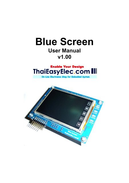
<strong>Blue</strong> <strong>Screen</strong><br />
User Manual<br />
v1.00
2<br />
<strong>Blue</strong> <strong>Screen</strong> Manual<br />
1. Introduction<br />
<strong>Blue</strong> <strong>Screen</strong> is a touch screen development board comes with<br />
NXP’s powerful ARM7 LPC2378, resistive-type-2.8-inch touch<br />
screen TFT LCD, micro-SD card socket and 8kB EEPROM.<br />
With full of peripheral drivers and advance software modules e.g.<br />
screen object manager, command line interface, SPI interface, I2C<br />
interface. The board is suited for all levels of developer. Any<br />
technical problem about coding, please feel free to post it in our<br />
webboard.
3<br />
<strong>Blue</strong> <strong>Screen</strong> Manual<br />
2. Features<br />
Hardware<br />
- 240x320 pixels TFT LCD with touch screen<br />
- NXP’s ARM7 LPC2378<br />
- Micro-SD card socket (connected via SPI interface) support up<br />
to 2GB capacity (High capacity: ‘HC’ type not supported)<br />
- On board 8kB EEPROM (the last 128 bytes are reserved for<br />
screen calibrated parameters)<br />
- 1 port ThaiEasyElec’s module connector consisting of SPI and<br />
UART signals from MCU<br />
- UART connector for command line interface and in-system<br />
programming (TTL 3.3v with 5v tolerant)<br />
- 16 ports GPIO<br />
- Mini-B USB connector (the board is powered from USB<br />
connector)<br />
Software<br />
Demonstrating application<br />
- MP3 player with graphic user interface (ThaiEasyElec’s<br />
VS1011 Module required)<br />
Command line interface software module<br />
- Show image from SD card<br />
- SD card commands e.g. change directory, list, open read, open<br />
write<br />
- Audio related commands e.g. play, pause, increase, decrease<br />
volume<br />
<strong>Screen</strong> object software module<br />
- Design your screen with object oriented method, the running<br />
background software will manage which object should be operated<br />
Low level drivers<br />
- LCD driver<br />
- Touch screen controller (AD7843) driver<br />
- Serial port<br />
- SPI interface<br />
- I2C interface
4<br />
<strong>Blue</strong> <strong>Screen</strong> Manual<br />
3. Requirement<br />
- USB cable (type A to mini-B) for supplying the board<br />
- ThaiEasyElec’s VS1011 module (optional) for MP3 player<br />
application (free earphone)<br />
- ThaiEasyElec’s USB to serial and cable (optional) for command<br />
line interface<br />
- Stylus (optional)<br />
- Micro-SD card (optional)<br />
- Programmer/Debugger (optional) ULink and mini N-Link are<br />
supported<br />
VS1011E Module USB mini B to Serial Stylus<br />
Mini SD Card<br />
mini N-link ARM USB JTAG
5<br />
<strong>Blue</strong> <strong>Screen</strong> Manual<br />
4. Drawing
6<br />
<strong>Blue</strong> <strong>Screen</strong> Manual<br />
5. Getting start<br />
5.1 Peripherals<br />
1. USB connector (mini-B)<br />
2. Reset button<br />
3. JTAG connector<br />
4. ThaiEasyElec’s module connector<br />
5. Console (command line interface connector, UART0)<br />
6. ISP Jumper<br />
7. Micro-SD card socket<br />
8. 16-bit GPIO<br />
9. 4 green LEDs<br />
10. 2.8-inch touch screen LCD
7<br />
<strong>Blue</strong> <strong>Screen</strong> Manual<br />
5.2 Power it on<br />
Connect the board with your computer via USB cable as seen in<br />
picture.<br />
The board shows “Press the screen to recalibrate within 3 (..2..1)<br />
seconds”. In this state, if you want to recalibrate the screen, press<br />
on it. Anyway, the board is calibrated from our factory so users<br />
don’t need to do it again.<br />
When the board starts up, it loads calibrated parameters from last<br />
128 bytes of EEPROM (see function AppCalibrate<strong>Screen</strong>() in<br />
app_blue_screen.c). These parameters are used to calculate<br />
which point the screen is pressed. They are variable on each<br />
board. In case that user overwrites some of these data in<br />
EEPROM. At the starting up, the calibration state (picture below)<br />
will show automatically without waiting.
8<br />
<strong>Blue</strong> <strong>Screen</strong> Manual<br />
In order to recalibrate the screen, there would be 25 points on the<br />
screen to be pressed. For each point, user needs to touch it twice.<br />
For accuracy, please touch it slowly and a stylus should be used.<br />
When finishing, the MP3 Player screen will be shown.<br />
5.3 Creating project with Keil<br />
The board is supplied with codes. Users have to make project<br />
yourself. This guide is an example for Keil. Firstly, you have to<br />
create a project. And select the device as “LPC2378”
9<br />
<strong>Blue</strong> <strong>Screen</strong> Manual<br />
Secondly, set the XTAL frequency as 20 MHz. This is very<br />
important; one downloading the firmware via JTAG with wrong<br />
setting will cause the board not to be programmable anymore. If<br />
this situation occurs, one way to recover is to program it with Flash<br />
Magic.<br />
Thirdly, replace the LPC2300.s file with the one you got from our<br />
website. And then add all other source files (.c) in the project. And<br />
also add group “efs” and add all source files in folder “efs”. For<br />
more detail about “efs” (stand for embedded file system) see<br />
appendix.
10<br />
<strong>Blue</strong> <strong>Screen</strong> Manual<br />
After these settings, the project should be compiled without any<br />
errors (some warnings may occur). The project workspace should<br />
be seen as below.
11<br />
<strong>Blue</strong> <strong>Screen</strong> Manual<br />
5.4 Source files description<br />
Header files (only important files are shown)<br />
1. hw_blue_screen.h : define hardware, for example : TC_CS is at<br />
port 2.2<br />
#define TC_CS_DPRT FIO2DIR<br />
#define TC_CS_PRTS FIO2SET<br />
#define TC_CS_PRTC FIO2CLR<br />
#define TC_CS_PIN 2<br />
DPRT : direction port<br />
PRTS : port set<br />
PRTC : port clear<br />
PIN : pin number in the port<br />
These may look awkward, but it’s very easy to change some<br />
pins.<br />
2. app_config.h : this file is used to configure many parameters<br />
various on each project. Header file including are in this file.<br />
And this file is included in most of source file. So which<br />
declaration shared on more than one source file should be<br />
declared on this file. This file also has function declarations<br />
from app_blue_screen_demo.c<br />
3. All other header files are subjected to declare functions only.<br />
Source files (only important files are shown)<br />
1. main.c : background functions are here including timer interrupt<br />
service routine (T0_IRQHandler()), i/o initialization (io_init()). In<br />
case that user need to use more peripherals, PINSEL may be<br />
set in io_init(). Notice that AppInit() and AppRun() are called<br />
from main(), user application may be modified (or recreate)<br />
using these functions.
12<br />
<strong>Blue</strong> <strong>Screen</strong> Manual<br />
2. app_blue_screen.c : most of application are here except the<br />
graphic user interface which is in app_screen_obj.c<br />
3. screen_obj.c : this is the code running in the background of<br />
screen object management. From the AppScanPen() in<br />
app_blue_screen.c, the screen position and the pen status are<br />
send to ScrObjDo(). This point is called “global position”<br />
because it refers the hold screen. In ScrObjDo(), each object<br />
are determined whether the screen position is in its area<br />
considering from its origin and its size. Then “.do()” of targeted<br />
object will be processed with “local position” got from minus of<br />
global position and the object’s origin.<br />
4. app_screen_obj.c : in this file, each object’s parameter are<br />
defined here including origin, horizontal and vertical size, do()<br />
and draw() function and etc. A part of code from this file is<br />
shown below.<br />
#define SO_VOLUME 0 // (1)<br />
(10)<br />
so_obj[SO_VOLUME].hsize = 16; // (2)<br />
so_obj[SO_VOLUME].vsize = 108; // (3)<br />
so_obj[SO_VOLUME].horigin = 284; // (4)<br />
so_obj[SO_VOLUME].vorigin = 20; // (5)<br />
so_obj[SO_VOLUME].stat = SO_ST_ON; // (6)<br />
so_obj[SO_VOLUME].val = 60; // (7)<br />
so_obj[SO_VOLUME].draw = volume_draw; // (8)<br />
so_obj[SO_VOLUME].do_ = volume_do; // (9)<br />
so_obj[SO_VOLUME].task100ms = volume_task100ms;//<br />
so_obj[SO_VOLUME].is_white = volume_is_white; // (11)<br />
Line (1) is to dedicate that, for this screen (MP3 player screen).<br />
The volume bar is the number 1 object.<br />
Line (2) and (3) define width and height of the object<br />
respectively.
13<br />
<strong>Blue</strong> <strong>Screen</strong> Manual<br />
Line (4) and (5) define horizontal and vertical origin of the<br />
object.<br />
Line (6) enables this object.<br />
Line (7) sets default value of the object (value may be variable<br />
for each type of object).<br />
Line (8) – (11) set the addresses of these function to there<br />
corresponding function.<br />
Note that “so_obj” is structure type variable. User may change<br />
its parameter when need. So in case that user designs more<br />
than one screen in an application. The array “so_obj” can be<br />
redefined again and again for each screen.<br />
For more detail about “so_obj” please see in screen_obj.h.<br />
5.5 Image generating<br />
In the MP3 player application, most of images seen on the screen<br />
are generated from JPEG files or Bitmap files with the software<br />
called “bmp2h_conv”. The last version is 5.1 allows bigger size of<br />
image. This part of manual shows step by step how to implement<br />
these pictures into your project.<br />
Firstly, create your image using Paint or whatever you like.<br />
Secondly, run bmp2h_conv and load your image. The default<br />
configurations of this version are supported for this type of LCD.<br />
There is nothing to be worried about these options.
14<br />
<strong>Blue</strong> <strong>Screen</strong> Manual<br />
At “To :” textbox, change the name of image code to anything you<br />
like or you may change it later after the header file is generated.<br />
This image is named as “pic_button1” in this project.<br />
Next, click “Generate” and specify the target file name.<br />
Finally, copy the generated file to the project folder and include it.<br />
As seen in app_screen_obj.c this image is included as<br />
“pic_button1.h”.
15<br />
<strong>Blue</strong> <strong>Screen</strong> Manual<br />
In order to display this image on the screen, see function<br />
bt1_draw() in app_screen_obj.c. First the area is filled with a<br />
rectangular. Then it’s overfilled with pic_button1 image with the<br />
offset pointer at<br />
so_obj[SO_BT1].val*(so_obj[SO_BT1].hsize*so_obj[SO_BT1].vsiz<br />
e)<br />
with value of “val” at 0-3, four styles button can be displayed<br />
occasionally.<br />
Notice about “TS_MODE_NORMAL” in function bt1_draw(). This is<br />
mode of displaying something on the screen. See appendix for<br />
more detail.
16<br />
<strong>Blue</strong> <strong>Screen</strong> Manual<br />
5.6 Programming, Debugging and Command line interface<br />
5.6.1 JTAG Interface<br />
<strong>Blue</strong> <strong>Screen</strong> supports JTAG interface for debugging and programming.<br />
Connect JTAG cable so the pin#1 is on the same side with reset switch,<br />
see picture below.
17<br />
<strong>Blue</strong> <strong>Screen</strong> Manual<br />
For Keil’s software, on the target’s option select ‘Debug’ and configure<br />
the flash programmer as follow.<br />
Also select ‘Settings’ and set MAX JTAG Clock not over than 200kHz if<br />
you are using mini N-Link.
18<br />
<strong>Blue</strong> <strong>Screen</strong> Manual<br />
Back to target’s option select Utilities and configure as follow.
19<br />
<strong>Blue</strong> <strong>Screen</strong> Manual<br />
Select setting and add programming algorithm as follow.
20<br />
<strong>Blue</strong> <strong>Screen</strong> Manual<br />
5.6.2 UART port<br />
To communicate the board with command line interface, HyperTerminal<br />
can be used. Set the COM port as follow.
21<br />
<strong>Blue</strong> <strong>Screen</strong> Manual<br />
This UART port also served for ISP (In-system programming), which<br />
user can use software like Flash Magic to program the MCU. To do this,<br />
place a jumper on J1 and then press reset. Now the MCU should starts<br />
with ISP boot loader.
22<br />
<strong>Blue</strong> <strong>Screen</strong> Manual<br />
Appendix<br />
1. TS_MODE (refers to tslcd_elt240320tp.h)<br />
TS_MODE is display mode used in functions start with TSLCD.<br />
Now there are 3 modes available, TS_MODE_NORMAL,<br />
TS_MODE_INVERSE and TS_MODE_FULL.<br />
- TS_MODE_NORMAL : To displaying a circle or some images<br />
having white background, user may want this white background to<br />
be transparent. Using this mode, all pixel having value 0xFFFF will<br />
considered as ‘background’ and it will be display as read-back<br />
color. The example of this mode displaying is the volume bar.<br />
There you can see blue background instead of white.<br />
- TS_MODE_INVERSE : As it’s name “inverse”. The circle or<br />
rectangular drawn will have inverse color to the old color. Color<br />
parameter sent to the function will be ignored.<br />
- TS_MODE_FULL : In case of showing a text message again and<br />
again in the same area. You need the use this mode as the blank<br />
space will be filled with background color. Anyway, displaying an<br />
image (TSLCDShowPic2()) with this mode all color from original<br />
image code will be display including white color.<br />
Note that a rectangular doesn’t have blank space; in this case<br />
TS_MODE_NORMAL and TS_MODE_FULL have same effect.<br />
2. Pen status (refers to app_config.h)<br />
Pen status or in code “pstatus” means the current state of pen.<br />
This is useful parameter sent to ScrObjDo(). There are 4 available<br />
statuses:
23<br />
<strong>Blue</strong> <strong>Screen</strong> Manual<br />
- PST_NOTFOUND : means that the screen is not pressed.<br />
- PST_DOWN : occurs once the screen is pressed.<br />
- PST_HOLD : occurs continuously while the screen is pressed.<br />
- PST_UP : occurs once the screen is released.<br />
3. Embedded file system library (EFSL)<br />
Embedded file system library using in this application is free library<br />
downloadable from http://sourceforge.net/projects/efsl/ . It’s limited<br />
to SPI only (LPC23xx’s MCI is not supported). It’s very easy to port<br />
it to your existing hardware. AVR, NXP’s ARM7, and some other<br />
platform have already had example.<br />
In this application lpc200_spi.c is modified from original code. It is<br />
the bridge between our SPI library and EFSL. Other files is also<br />
modified (some lines are commented) to decrease warnings and<br />
errors.