BP 4.5 - SPECS Surface Nano Analysis GmbH
BP 4.5 - SPECS Surface Nano Analysis GmbH
BP 4.5 - SPECS Surface Nano Analysis GmbH

You also want an ePaper? Increase the reach of your titles
YUMPU automatically turns print PDFs into web optimized ePapers that Google loves.
<strong>BP</strong> <strong>4.5</strong><br />
SPM Control System Base Package <strong>4.5</strong><br />
Key Features<br />
• Exceptional Signal Quality<br />
• Expandable and Future Proof<br />
Hardware and Software<br />
• Powerful, Flexible and<br />
Customizable User Interface<br />
• Works with any SPM<br />
• Most Advanced Measurement<br />
Techniques
Innovation in surface Spectroscopy and<br />
microscopy systems<br />
<strong>SPECS</strong> leads the way in state-of-the-art<br />
technology for electron spectroscopy and<br />
scanning probe microscopy.<br />
Our key to success is know-how, experience,<br />
close contact to scientists from all over the world,<br />
customer orientation, reliable quality control,<br />
and dynamic research and development.<br />
<strong>SPECS</strong> <strong>Surface</strong> <strong>Nano</strong> <strong>Analysis</strong> <strong>GmbH</strong><br />
<strong>SPECS</strong> headquarters, with more than 150<br />
employees, is located in the center of Germany’s<br />
capital Berlin, with subsidiaries in Switzerland<br />
(<strong>SPECS</strong> Zurich <strong>GmbH</strong>) and in the USA (<strong>SPECS</strong><br />
Inc.). Furthermore, we have liaison offices and<br />
are represented all over the globe by our sales<br />
partners.<br />
We are a team of scientists and engineers who<br />
have been dedicating their knowledge and<br />
experience to the development, design, and<br />
production of instruments for surface science,<br />
materials research, and nanotechnology since<br />
1983.<br />
SPM Control System Base Package
<strong>Nano</strong>nis <strong>BP</strong> <strong>4.5</strong><br />
The Expandable Engine for Your SPM Project<br />
The Base Package of the <strong>Nano</strong>nis Control<br />
System combines exceptional signal<br />
quality and a flexible, powerful, and userfriendly<br />
software interface making it the<br />
ideal choice for the most demanding SPM<br />
applications.<br />
<strong>Nano</strong>nis SPM Control System<br />
From signal conditioning and AD/DA conversion<br />
to fast signal processing via a comprehensive and<br />
clear graphical user interface, the <strong>Nano</strong>nis SPM<br />
Control System provides a powerful framework<br />
that can be further adapted and extended<br />
with a wide range of add-on modules. All basic<br />
processes such as Z-control, scan control, data<br />
acquisition, data monitoring, spectroscopy,<br />
atomic manipulation and lithography are<br />
included, allowing easy control of most STM and<br />
AFM operations.<br />
Fully digital system<br />
All analog signals are converted immediately into<br />
the digital domain, where all signal processing<br />
is performed, making them essentially immune<br />
to external noise and crosstalk and ensuring the<br />
best possible signal quality, which is crucial for<br />
SPM applications.<br />
In combination with the powerful software<br />
package, signal routing can be adapted and<br />
optimized on the fly with the press of a button<br />
instead of adjusting external hardware cabling. A<br />
fully digital system is also flexible and scalable,<br />
since software adaptations are all that is needed<br />
for rapid custom developments of the system.<br />
Real-time controller RC5<br />
NI-7965R FPGA Card<br />
Signal distribution<br />
Host computer<br />
Windows 7 or 8<br />
Dual or quad display<br />
Graphical user interface<br />
Data storage<br />
TCP/IP communication<br />
Buffered<br />
transfer<br />
Pulse counters<br />
Pulse generators<br />
Device control<br />
Device readout<br />
Optional<br />
precision clock<br />
Clock I/O<br />
4x high speed DIO<br />
4 x 8 bit DIO ports<br />
NI-8115 RT-system<br />
Core i5 processor<br />
LabVIEW RT OS<br />
Time-critical loops<br />
PI controllers<br />
Data acquisition<br />
Scan generation<br />
State machines<br />
...<br />
PXIe bus<br />
Oscillation<br />
control<br />
Digital filters<br />
Oversampling<br />
Dithering<br />
hrDAC<br />
Lock-ins<br />
Oscilloscope<br />
FFT<br />
SC 01 SC 02 SC 03 OC 01-03<br />
ADC/DAC Driver, control logic<br />
18 bit<br />
1 MS/s<br />
20 bit<br />
1 MS/s<br />
20 bit<br />
1 MS/s<br />
Signal Conversion SC5<br />
LP<br />
100 kHz<br />
LP<br />
40 kHz<br />
LP<br />
1 MHz<br />
8 analog inputs<br />
8 analog outputs<br />
fast analog output<br />
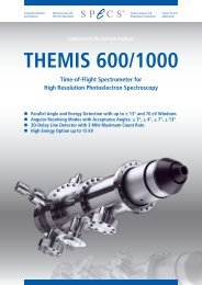
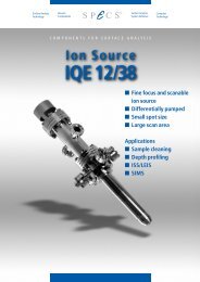
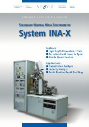
Simplified block diagram<br />
of the <strong>Nano</strong>nis Base<br />
Package <strong>4.5</strong>
Plenty of channels<br />
Signal analysis and monitoring<br />
The generic analog interface provides 48 live<br />
signals: 8 inputs, 8 outputs and 32 internal<br />
signals, with up to 24 signals that can be acquired<br />
simultaneously. This allows the connection of<br />
signals including bias voltage, current, scan<br />
signals, lock-in signals, etc., and combination<br />
of different signals in the digital domain. The<br />
hardware is designed to support up to 24 inputs<br />
and 24 outputs, plus multiple PLLs for AFM<br />
operation, thus allowing operation of even the<br />
most complex measurement set-ups.<br />
All signals can be inspected with the FFT<br />
spectrum analyzer, dual-channel oscilloscope,<br />
signal charts, and history panels. Such fully<br />
digital and integrated software instruments are<br />
much more efficient in use, less invasive, better<br />
in performance, and lower in cost than their<br />
external counterparts.<br />
The ability to digitally route live signals to software<br />
instruments during active measurements without<br />
any negative impact on signal quality is truly<br />
invaluable when optimizing the experimental setup,<br />
eliminating disturbances and thus improving<br />
the quality of scientific results.<br />
Highest signal performance<br />
High resolution AD/DA conversion<br />
“There is plenty of room at the bottom”, said<br />
Richard Feynman when he described his vision<br />
of the science that led to nanotechnology.<br />
Enormous resolution is required to reveal the<br />
smallest features, while maintaining a large<br />
dynamic range.<br />
The dual-channel<br />
triggering oscilloscope<br />
makes monitoring,<br />
analyzing, and recording<br />
signals an easy task<br />
This large number of live signals can not<br />
only be monitored, but also all signals are<br />
displayed as real world numbers in floatingpoint<br />
representation, with assigned SI units for<br />
immediate quantitative results, without the need<br />
of additional calibrations during data analysis.<br />
The signal frontend of the Base Package, the<br />
<strong>Nano</strong>nis SC5, uses the latest advances in AD/<br />
DA conversion technology, in combination with<br />
sophisticated digital filtering, oversampling, and<br />
dithering techniques, to provide the highest<br />
resolution.<br />
SPM Control System Base Package
22-bit resolution with patented<br />
hrDAC technology<br />
Adaptive oversampling high<br />
resolution data acquisition<br />
A custom-designed input stage allows acquisition<br />
of the weakest analog signals, without<br />
compromises in dynamic range. The signals<br />
are digitized at an early stage with 18-bit AD<br />
converters running at 1 MS/s and then processed<br />
in the digital domain. Adaptive oversampling<br />
allows the ability to always obtain the best signalto-noise<br />
performance for a given data acquisition<br />
rate. The user doesn’t need to care about<br />
adjusting time constants, as the data acquisition<br />
automatically provides the best setting.<br />
5<br />
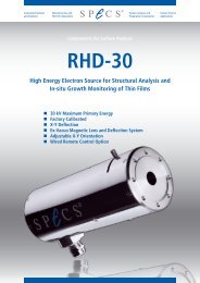
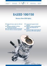
A 500 µV sweep measured under equal conditions: The<br />
SC5 shows a 16x higher resolution, higher precision,<br />
stability and lower noise compared to the previous<br />
generation<br />
All outputs of the SC5 use 20-bit resolution,<br />
1-ppm precision DACs, the best available on the<br />
market. Just a few years ago, similar performance<br />
on multiple outputs would have been impossible<br />
to realize. The patented hrDAC technology<br />
turns these state-of-the-art converters into real<br />
22-bit devices, which in a traditional approach<br />
would fill a rack with single-channel instruments<br />
and cost ten times as much. Measurements<br />
requiring smallest modulations with large offsets<br />
are thus possible without the need for drift- and<br />
error-inducing analog circuits or external mixers<br />
or attenuators. The impressive dynamic range<br />
also eliminates the need for switching gains,<br />
therefore coordinates are absolute over the full<br />
signal and scan range.<br />
Lowest drift with temperature<br />
stabilization<br />
Scanning probe microscopes require very stable<br />
signals over long measurement times. For this<br />
reason, the SC5 is equipped with a custom<br />
temperature-stabilized, high precision voltage<br />
reference. The reference has a very low inherent<br />
noise and drift. Temperature stabilization<br />
combined with thermal decoupling allows<br />
reduction of the temperature coefficient to below<br />
3 µV/°C and output drift to below 1.5 µV in 12<br />
hours at 0 V.<br />
State of the art optional digital lockin<br />
amplifier with 40 kHz bandwidth<br />
DC signals are not the only strength of the<br />
SC5: Each output has a bandwidth of 40 kHz,<br />
and measurement schemes requiring a lockin<br />
amplifier (e.g. dI/dV spectroscopy) can be<br />
realized very easily. With 1 MS/s sample rate,<br />
a THD+N larger than 93 dB (18 V p-p<br />
at 1 kHz),<br />
linearity down to below -120 dB, up to 22-bit<br />
resolution, and multiple demodulators, the SC5<br />
outputs offer a powerful measurement tool<br />
also for the most demanding AC experiments<br />
requiring low harmonic distortion and multiple<br />
harmonic demodulation.
Lowest noise<br />
Lowest output noise floor<br />
When experiments involve energies of a few µeV,<br />
high resolution alone is not the only prerequisite<br />
for a measurement interface: Low noise is<br />
of utmost importance, and the SC5 delivers<br />
impressive performance on both inputs and<br />
outputs. The noise floor of the SC5 lies below<br />
25 nV/√Hz with an output voltage range of ±10<br />
V. Despite its large bandwidth of 40 kHz, the<br />
output noise does not exceed 10 µV RMS at a<br />
measurement bandwidth of 300 kHz, meaning<br />
that the noise contribution of the SC5 is irrelevant<br />
in experimental situations.<br />
Stability at its best: More than a one order of magnitude<br />
improvement over the previous generation<br />
Additional analog and digital<br />
interfaces<br />
High-speed analog output<br />
A massive reduction in output noise ensures the best<br />
possible measurement results<br />
Lowest 1/f noise outputs<br />
In contrast to broadband noise, which can be<br />
easily filtered, 1/f noise cannot be eliminated<br />
and becomes an issue for experiments requiring<br />
signals to be very stable. The outputs of the<br />
SC5 have been designed keeping this in mind,<br />
leading to a noise level below 750 nV peak-peak<br />
(0.1 – 10 Hz, ±10 V range), or about 2 23 times<br />
smaller than the maximum output signal.<br />
Designed for providing sawtooth waveforms for<br />
coarse positioning applications, the 9th analog<br />
output of the SC 5 has a bandwidth of 500 kHz.<br />
With the flexible software function generator, the<br />
user can use this additional channel to output<br />
arbitrary periodic waveforms.<br />
Digital inputs and output<br />
32 bidirectional digital lines give sufficient<br />
flexibility for read-out and control of both<br />
<strong>Nano</strong>nis and external instruments. For high<br />
speed counting applications, four dedicated lines<br />
allow counting rates of up to 100 Mc/s.<br />
SPM Control System Base Package
User interface<br />
7<br />
Most advanced user interface for<br />
SPM<br />
One of the key parameters determining the<br />
productivity of a measurement system is the<br />
user-machine interface, or, in aviatic terms, the<br />
cockpit. The cockpit of the <strong>Nano</strong>nis SPM Control<br />
System, its user interface, is designed to be a<br />
pleasure to use, and to allow a safe, effective,<br />
and productive workflow, without limitations for<br />
the user. Let your SPM fly without crash landings.<br />
Interactive scan control<br />
The scan control module is interactive and<br />
dynamic, allowing instantaneous control of the<br />
SPM tip in real-time and in any situation. Mouse<br />
button and scroll wheel control allows on the fly<br />
adjustments and data visualization optimization.<br />
By this, it is possible to zoom in, adapt scan frame<br />
parameters and paste multiple scanned images<br />
to the background for reference. With up to seven<br />
scan windows it is easy to keep an overview over<br />
all acquired data. Arbitrary rotation of the scan<br />
plane on any of the X,Y and Z axis even allows to<br />
scan on the “walls” of high aspect-ratio samples.<br />
Advanced multipass techniques with<br />
scripting functions<br />
Many experimental techniques require the tip to<br />
be scanned multiple times on the same line while<br />
acquiring a scan image. The <strong>Nano</strong>nis multi-pass<br />
function allows multiple passes with different<br />
setpoints, speeds, bias voltages, at constant tipto-sample<br />
distance, constant Z, or with any other<br />
parameter recorded during the previous pass.<br />
The scan control module<br />
gives the user a complete<br />
overview of the sample<br />
and full control of the SPM<br />
tip at any time
Versatile Z-controller<br />
Multiple passes can be time consuming when<br />
taking high resolution images, therefore<br />
optimizing the time for each scanned image<br />
can become crucial. The multipass function is<br />
therefore coupled with a scripting function, which<br />
makes it possible to run experiments like KPFM<br />
at real-time and deterministic speed just with a<br />
few script entries, and thus reduces time losses<br />
without the need for complex programming.<br />
Advanced 2D and 3D spectroscopy<br />
Advanced spectroscopy modules provide a set<br />
of flexible routines for experiments on a point,<br />
line, grid, or a cloud of points. Additionally, a<br />
“point and shoot” mode, where the user can<br />
interactively perform any experiment at a mouse<br />
click, and a fast spectroscopy mode allow precise<br />
and time-efficient spectroscopic measurements<br />
while scanning an image.<br />
The distance between tip and sample can be<br />
controlled by any signal or combination of signals.<br />
Quantitative parameters allow the application<br />
of control theory models and yield a further<br />
understanding of the tip-sample interaction. The<br />
user-configurable Z-controller allows on-the-fly<br />
switching between settings such as input signal<br />
and feedback parameters.<br />
And when it takes days to get the first high quality<br />
image, a tip crash is the last thing a researcher<br />
wants to happen. The SafeTip function takes<br />
care of retracting the tip should a potentially<br />
harmful event be detected. Not only is this<br />
function very fast, and designed to reduce creepinduced<br />
drift, but it also gives the user a variety<br />
of choices what to do in such an event, ranging<br />
from engaging coarse motion to retract the tip<br />
further, to a scan resume function which limits<br />
data losses while scanning.<br />
Spectroscopy modules are bias spectroscopy,<br />
Z-spectroscopy, and generic sweep where any<br />
output or parameter can be swept while any<br />
number of other selected channels can be<br />
recorded. Each module is designed to optimize<br />
precision and time requirements of the<br />
experiments. In the case of bias spectroscopy, a<br />
bias-dependent measurement resolution reduces<br />
the required measurement time per acquired<br />
spectroscopy curve, while disabling of the dI/dV<br />
AC modulation signal when in feedback improves<br />
reliability when determining the exact Z-position.<br />
In the same way, in the Z-spectroscopy module,<br />
a dedicated safety loop reduces the risk of tip<br />
crashes.<br />
Easy expansion through add-on<br />
modules<br />
The modularity of the software is a key advantage<br />
in cost optimization: Additional software modules<br />
can be added when experimental needs require<br />
them. Even modules which are not available<br />
at the time of purchase of the Base Package,<br />
can be purchased at a later stage, making the<br />
instrument highly future-proof. The addition of<br />
new modules does not require any hardware or<br />
software installation, and can be performed in a<br />
very short time.<br />
In addition to the already implemented modules,<br />
any user-defined experiment written in LabVIEW<br />
can be integrated into the spectroscopy<br />
functionality of the <strong>Nano</strong>nis SPM Control System,<br />
by using the Programming Interface.<br />
SPM Control System Base Package
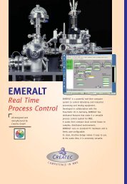
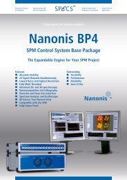
High resolution images measured<br />
with the <strong>Nano</strong>nis <strong>BP</strong> <strong>4.5</strong><br />
9<br />
The modules include:<br />
• Lock-in detector<br />
• Programming interface<br />
• Time-resolved measurement module with<br />
1 MS/s oscilloscope/FFT<br />
• Atom tracking<br />
• Kelvin controller<br />
• Interferometer controller<br />
In addition to the modules listed above, pulse<br />
counters, a function generator for slip-stick piezo<br />
drive, a PI controller, and large number of coarse<br />
approach motor control modules for commercial<br />
and home-built microscopes are available on<br />
request.<br />
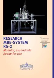
AFM<br />
STM<br />
Graphene on Iridium (111)<br />
On the fly switch between NC-AFM (top) and<br />
STM (bottom) mode using a KolibriSensor.<br />
Scan size: 6.7 nm x 6.7 nm<br />
AFM: Δf = 3.6 Hz, STM: U T<br />
= +0.13 V, I T<br />
= 1.8 nA<br />
-1.19 Hz<br />
-238 pA<br />
-2.62 Hz<br />
-385 pA<br />
Constant height images of Graphene on Iridium (111) at -400 mV bias voltage: (left) frequency shift and (right) the<br />
corresponding tunneling current. Scan size: 4.3 nm x 4.3 nm
LabVIEW Programming<br />
Interface for experiments<br />
Flexibility for the user<br />
Competitive advantage in research is often based<br />
on the modification of an instrument that allows<br />
the researcher to perform experiments in a way<br />
nobody else has done before. This is where the<br />
LabVIEW Programming Interface steps in: to<br />
give you the building blocks to design your own<br />
experiment.<br />
The LabVIEW Programming Interface consists<br />
of libraries to access the controls and functions<br />
of the graphical user interface. It is used to<br />
automate experiments, sequences, calibration<br />
routines and experimental procedures. Polling of<br />
parameters and signals at high rates allows for<br />
supervision and alarm settings, and many other<br />
features.<br />
Elaborated hardware design<br />
Only best-in-class components<br />
The electronic mainboard of the SC5 is a<br />
showcase for the best available active digital and<br />
analog electronic components on the market.<br />
Cheaper solutions leading to compromises<br />
have been discarded from the beginning, since<br />
only by meticulously choosing the best suitable<br />
components down to each single resistor, can the<br />
exceptional performance of the SC5 be achieved.<br />
Instead of using a simple scripting language, or<br />
a dedicated language, the <strong>Nano</strong>nis SPM Control<br />
System provides full access to all the features<br />
provided with LabVIEW: graphs, database access,<br />
convenient data handling, TCP/IP, GPIB, RS232,<br />
USB access to other instruments, signal analysis<br />
functions and much more.<br />
SPM Control System Base Package
Future-proof and modular<br />
platform<br />
11<br />
Modular processing power<br />
The “brain” of the <strong>Nano</strong>nis Base Package is the<br />
real-time controller RC5. By using the latest FPGA<br />
and CPU technology, the RC5 provides enough<br />
speed, connectivity and processing power for the<br />
most demanding tasks. Modularity doesn’t stop<br />
there either: Both FPGA and real-time modules<br />
are easily exchangeable, and can be updated<br />
should significantly faster modules be available<br />
in the future.<br />
Linear power supply with automatic<br />
line voltage detection<br />
The SC5 is powered by a linear power supply.<br />
Switching power supplies or DC/DC converters<br />
are not used anywhere in the instrument. Despite<br />
being equipped with a linear power supply, there<br />
is no need to manually adjust the line voltage to<br />
local circumstances: An intelligent circuit detects<br />
the line voltage and automatically configures the<br />
power transformer inputs.<br />
Preamplifier power supply<br />
An auxiliary power supply is available for powering<br />
external instruments like e.g. preamplifiers. With<br />
its low-noise, preregulated ±15 V voltage with up<br />
to 300 mA current delivery capability, it makes<br />
external power supplies unnecessary.<br />
Easy integration of additional<br />
experiments<br />
When a new experiment is started, often not all<br />
requirements are already known in detail. This<br />
is no problem with the SC5 and its real-time<br />
controller RC5:<br />
• The addition of one or more <strong>Nano</strong>nis<br />
Oscillation Controllers (OC4), which<br />
extends the frequency range to 5 MHz,<br />
is straightforward, should a larger signal<br />
bandwidth be required.<br />
• Communication, triggering and control of<br />
additional external instruments is an easy task<br />
thanks to the various digital communication<br />
options of the RC5.
Hardware add-ons<br />
Modular Control System<br />
Modularity of the <strong>Nano</strong>nis SPM control system<br />
means that the hardware required for a given<br />
experimental situation can be tailored to the<br />
users‘ needs. This is the most flexible and at the<br />
same time cost-effective solution, and offers<br />
the best performance since each instrument is<br />
highly optimized. Hardware add-ons include the<br />
oscillation controller, high-voltage amplifiers,<br />
piezo drivers, and adaptation kits for commercial<br />
microscopes.<br />
High Voltage Amplifiers<br />
<strong>Nano</strong>nis HVA4<br />
The <strong>Nano</strong>nis HVA4 is a low noise, six-channel<br />
high-voltage amplifier specifically designed<br />
for nanopositioning applications using piezo<br />
elements. Three different models with maximum<br />
output voltages of ±140 V, ±220 V or ±400 V let the<br />
user choose an optimal setup for his application.<br />
Oscillation Controller with PLL<br />
<strong>Nano</strong>nis OC4 and OC4 Dual<br />
The Oscillation Controller (OC4) with digitally<br />
integrated PLL adds dynamic AFM capabilities<br />
to the <strong>Nano</strong>nis Control System. The z-feedback<br />
can regulate on any signal coming from the<br />
mechanical resonator with any predefined<br />
SafeTip conditions. Imaging modes include<br />
among others: non-contact AFM, intermittent<br />
contact mode, phase imaging, dissipation. With<br />
an input bandwidth of 5 MHz, the OC4 can<br />
operate any type of cantilever, tuning fork, needle<br />
sensors, etc. and their harmonics. And, it can be<br />
used as a powerful digital lock-in amplifier.<br />
With differential inputs and a noise spectrum<br />
density below 1 μV/√Hz at 300 Hz at gain 40<br />
(input shorted), the HVA4 sets the standard<br />
for low-noise HV applications. The SNR<br />
of the HVA4 is so large that even with a<br />
10 μm Z-range piezo tube, the noise level in Z<br />
corresponds to less than 2 pm (RMS), far below<br />
the corrugation of the sample.<br />
SPM Control System Base Package
Piezo Drivers<br />
13<br />
<strong>Nano</strong>nis PMD4<br />
<strong>Nano</strong>nis PD5<br />
The <strong>Nano</strong>nis PD5 combines the functionality of<br />
the HVA4 and of the PMD4 into a single enclosure.<br />
Five low-noise high voltage channels with the<br />
same specifications as the HVA4 are combined<br />
with eight outputs for driving low-capacitance<br />
piezo motors with software or handset control.<br />
The <strong>Nano</strong>nis PMD4 is a high performance piezo<br />
motor driver, designed to drive piezo positioners<br />
with a very wide range of specifications. Owing to<br />
its patented output drive technology, the PMD4<br />
is perfectly suited for driving piezo positioners in<br />
SPM applications, even under the most difficult<br />
conditions, e.g. at very low temperatures or with<br />
large capacitance piezo motors. The PMD4 is<br />
available with eight or sixteen output channels<br />
and a single waveform generator, or with eight<br />
output channels and two waveform generators.<br />
It can be remotely controlled in combination with<br />
a <strong>Nano</strong>nis SPM control system over its digital<br />
interface, or with the included handset. The<br />
amplitude of the output waveform can be varied<br />
continuously between 0 and ±400 V, and its<br />
frequency continuously between 1 Hz and 20 kHz.<br />
Adaptation kits<br />
For use with commercial microscopes<br />
Numerous adaptation kits are available to<br />
interface the <strong>Nano</strong>nis SPM Control System with<br />
most types of commercial microscopes including<br />
Omicron, Veeco (Bruker), JEOL, Createc, RHK<br />
and Unisoku. The original SPM cables connect<br />
directly to the pin-compatible interfaces, making<br />
a change of the control system extremely simple.
Specifications<br />
Technical data<br />
General<br />
Content of Delivery<br />
Cases<br />
Operating<br />
Temperature<br />
Compliance<br />
Warranty<br />
Documentation<br />
RC5<br />
Dimensions<br />
Weight<br />
Power Supply<br />
Real-time System<br />
Operating System<br />
FPGA Card<br />
Connectivity<br />
SC5<br />
Dimensions<br />
Weight<br />
Power Supply<br />
Electrical GND<br />
Real-time controller RC5,<br />
Signal conversion SC5, software<br />
and license, unlimited<br />
updates and support for one<br />
year, host computer (Option)<br />
Stackable benchtop cases, full<br />
metal enclosure<br />
+5° C to +35° C<br />
CE<br />
One year parts and labor (EU:<br />
two years) on defects in material<br />
and workmanship<br />
User manual describing<br />
hardware and installation,<br />
online user manual for<br />
graphical user interface<br />
32.5 x 28 x 21 cm<br />
7.8 kg<br />
Built-in universal power<br />
supply, max. 200 W,<br />
100 – 240 V, 50 - 60 Hz<br />
NI PXIe-8115 real-time system<br />
with Intel Core i5 CPU<br />
2.5 GHz, 2 GB RAM<br />
NI LabVIEW Real-Time OS<br />
NI PXIe-7965R<br />
3 x SC5 max., 3 x OC4 max.<br />
Total of max. 4 frontends<br />
R 32.5 x 28 x 7 cm<br />
4.2 kg<br />
Built-in linearly regulated<br />
power supply, toroidal<br />
transformer, automatic line<br />
voltage detection. Max. 51 W,<br />
100 – 240 V, 50 - 60 Hz<br />
10 kΩ AGND to chassis,<br />
decoupled from RC5<br />
Analog Inputs<br />
(all specifications for ±10 V input range)<br />
Hardware Interface<br />
Differential Input<br />
Voltage Range<br />
Differential Input<br />
Impedance<br />
Analog Bandwidth<br />
AD-converter<br />
Effective Resolution<br />
INL<br />
DNL<br />
Input Noise Density<br />
Measurement Noise<br />
12 h-Drift<br />
THD+N, 9 V Input<br />
Signal<br />
8 x BNC connectors,<br />
differential<br />
±10 V<br />
2 MΩ<br />
DC – 100 kHz (-3 dB),<br />
5 th -order Butterworth<br />
low-pass filter<br />
18-bit, no missing codes,<br />
1 MS/s<br />
20-bit @ 60 kS/s,<br />
24-bit @ 240 S/s<br />
(oversampling)<br />
±2 LSB typical<br />
±1 LSB typical<br />
< 150 nV/√Hz @ 10 kHz,<br />
< 650 nV/√Hz @10 Hz<br />
< 100 µVrms @ 1 MS/s,<br />
< 25 µVrms @ 60 kS/s,<br />
< 6.5 µVrms @ 240 S/s<br />
< 80 µV (< 100 µV) @ 0 V<br />
(@ 9.9 V)<br />
> 120 dB @ 100 Hz,<br />
> 95 dB @ 1 kHz,<br />
> 70 dB @ 10 kHz<br />
Analog Outputs<br />
(all specifications for ±10 V output range)<br />
Hardware Interface<br />
Output Voltage Range<br />
Output Impedance<br />
Analog Bandwidth<br />
DA Converter<br />
Effective Resolution<br />
8 x BNC connectors,<br />
referenced to AGND<br />
±10 V into 1 kΩ or larger<br />
(0 to +10 V with internal jumper<br />
per channel)<br />
15<br />
Analog Outputs<br />
(all specifications for ±10 V output range)<br />
Graphical User Interface<br />
INL<br />
DNL<br />
Output Noise Density<br />
Output Noise<br />
12h-Drift<br />
THD+N, 9 V Output<br />
Signal<br />
< ±2 LSB max. < ±1 LSB typical<br />
< ±1 LSB max. < 0.5 LSB<br />
typical<br />
< 25 nV/√Hz @ 100 Hz,<br />
< 75 nV/√Hz @ 1 Hz<br />
< 200 nVrms (0.1 – 10 Hz),<br />
< 10 µVrms (10 Hz – 300 kHz)<br />
< 1.5 µV (< 25 µV)<br />
@ 0 V (@ 9.9 V)<br />
> 93 dB @ 100 Hz, > 93 dB<br />
@ 1 kHz, > 79 dB @ 10 kHz<br />
Operating System<br />
Min. Requirements<br />
Recommended<br />
Configuration<br />
License<br />
Windows XP/Vista/7/8<br />
Windows 7 64-bit recommended<br />
Intel Core Duo 1.5 GHz or<br />
equiv., 2 GB RAM, 100 GB HD,<br />
two 19” screens with at least<br />
1280 x 1024 pixels<br />
Intel Core i5 2.5 GHz or<br />
equiv., 4 GB RAM, 1 TB HD,<br />
two 21” screens with 1600 x<br />
1200 or 1920 x 1200 pixels<br />
Unlimited in time,<br />
bound to RC5<br />
Digital Lines<br />
Ports<br />
4 x 8 lines on four D-sub<br />
9 female connectors<br />
Documentation<br />
Online help, F1 for context<br />
sensitive help, tip strips for<br />
each control element, printed<br />
hardware user manuals with<br />
operation instructions for<br />
related software modules<br />
Direction<br />
Signal<br />
Maximum Sampling<br />
Frequency<br />
Input or output for each line<br />
3.3 V TTL, max. 25 mA per line<br />
500 kHz<br />
Settings<br />
Configuration<br />
Signals<br />
For every session directory/<br />
user, settings, parameters and<br />
screen layouts<br />
High Speed Digital Lines<br />
Ports<br />
Signal<br />
Maximum Sampling<br />
Frequency<br />
4 x inputs and 4 x outputs on<br />
SMB male connectors<br />
3.3 V TTL, max. 33 mA per line<br />
200 MHz<br />
Signals<br />
Data Transfer<br />
Representation<br />
48 signals (inputs, outputs<br />
and internal signals), up to<br />
24 simulteneous signals for<br />
data display and acquisition<br />
Via TCP/IP, 2 kS/s default,<br />
up to 20 kS/s<br />
32-bit floating point,<br />
real world physical units<br />
Clock<br />
Ports<br />
Frequency<br />
Accuracy<br />
1 x input, 1 x output for active<br />
clock source<br />
10 MHz, square wave, 3.3 V<br />
± 50 ppm (standard clock),<br />
± 4 ppm (optional OCXO)
<strong>SPECS</strong> <strong>Surface</strong> <strong>Nano</strong> <strong>Analysis</strong> <strong>GmbH</strong><br />
Voltastrasse 5<br />
13355 Berlin / Germany<br />
www.specs.com<br />
T +49 30 46 78 24-0<br />
F +49 30 46 42 083<br />
E support@specs.com