SP4412A Electroluminescent Lamp Driver - Datasheet Catalog
SP4412A Electroluminescent Lamp Driver - Datasheet Catalog
SP4412A Electroluminescent Lamp Driver - Datasheet Catalog

You also want an ePaper? Increase the reach of your titles
YUMPU automatically turns print PDFs into web optimized ePapers that Google loves.
The external clock should have a 50% duty<br />
cycle and range from V DD<br />
-1V to ground. The<br />
maximum external clock frequency is 128 kHz.<br />
The coil is an external component connected<br />
from V BATTERY<br />
to pin 5 of the <strong>SP4412A</strong>. Energy<br />
is developed in the coil according to the equation<br />
E L<br />
=1/2LI 2 where the current I is defined as<br />
I=(V BATTERY<br />
-IR-V OL<br />
)/R T<br />
. In order to maximize<br />
the energy produced by the coil, V BATTERY<br />
should<br />
represent the largest voltage in the system (up to<br />
a maximum of 3.6 v); V BATTERY<br />
= 3.0 VDC with<br />
a 35mH/125Ω coil is a typical example. It is not<br />
necessary that V DD<br />
=V BATTERY<br />
. The coil operation<br />
is a function of the core material and winding<br />
used -- performance variances may be noticeable<br />
from different coil suppliers even though the<br />
values are the same. The Sipex <strong>SP4412A</strong> is<br />
final tested using a 35 mH/135 ohm coil. For<br />
suggested coil sources see page 8.<br />
The f COIL<br />
signal controls a switch that connects<br />
the end of the coil at pin 5 to ground or to open<br />
circuit. The f COIL<br />
signal is a 94% duty cycle<br />
square wave, switching at 1/4 the oscillator<br />
frequency, (for a 32 kHz oscillator f COIL<br />
is 8<br />
kHz). During the time when the f COIL<br />
signal is<br />
high, the coil is connected from V BATTERY<br />
to<br />
ground and a charged magnetic field is created<br />
in the coil. During the low part of f COIL<br />
, the<br />
ground connection is switched open, the field<br />
collapses, and the energy in the inductor is forced<br />
to flow toward the high voltage H-bridge<br />
switches. f COIL<br />
will send 16 of these charge<br />
pulses to the lamp, each pulse increases the<br />
voltage drop across the lamp in discrete steps. As<br />
the voltage potential approaches its maximum,<br />
the steps become shorter (see figure 1 on page 7).<br />
The H-bridge consists of two SCR structures that<br />
act as high voltage switches. These two switches<br />
control the polarity of how the lamp is charged.<br />
The SCR switches are controlled by the f LAMP<br />
signal which is the oscillator frequency divided<br />
by 128. For a 32kHz oscillator, f LAMP<br />
= 250Hz.<br />
When the energy from the coil is released, a high<br />
voltage spike is created triggering the SCR<br />
switches. The direction of current flow is<br />
determined by which SCR is enabled. One full<br />
cycle of the H-bridge will create 16 voltage steps<br />
from ground to 80V (typical) on pins 6 and 7<br />
which are 180 degrees out of phase with each<br />
other (see figure 3 on page 7). A differential view<br />
of the outputs is shown in figure 4 on page 7.<br />
ELECTROLUMINESCENT TECHNOLOGY<br />
What is electroluminescence?<br />
An EL lamp is basically a strip of plastic that is<br />
coated with a phosphorous material which emits<br />
light (fluoresces) when a high voltage (>40V)<br />
which was first applied across it, is removed or<br />
reversed. Long periods of DC voltages applied to<br />
the material tend to breakdown the material and<br />
reduce its lifetime. With these considerations in<br />
mind, the ideal signal to drive an EL lamp is a<br />
high voltage sine wave. Traditional approaches<br />
to achieving this type of waveform included<br />
discrete circuits incorporating a transformer,<br />
transistors, and several resistors and capacitors.<br />
This approach is large and bulky, and cannot be<br />
implemented in most hand held equipment. Sipex<br />
now offers low power single chip driver circuits<br />
specifically designed to drive small to medium<br />
sized electroluminescent panels. All that is<br />
required is an external inductor and an external<br />
clock signal.<br />
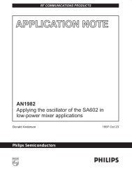
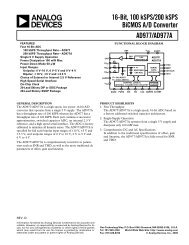
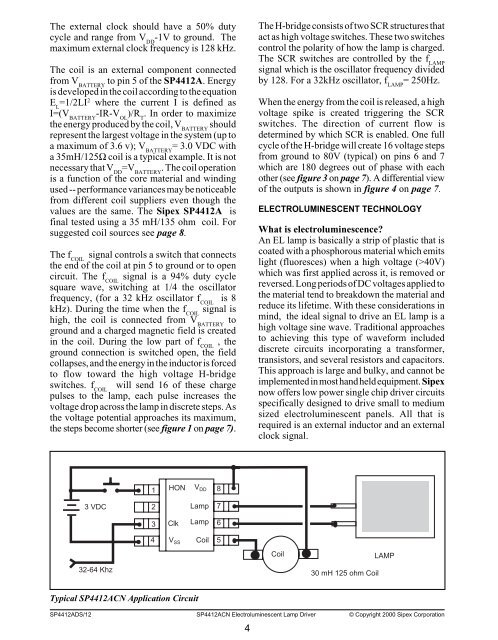
1<br />
HON<br />
V DD<br />
8<br />
3 VDC<br />
2<br />
<strong>Lamp</strong><br />
7<br />
3<br />
Clk<br />
<strong>Lamp</strong><br />
6<br />
4 Coil 5<br />
V SS<br />
Coil<br />
LAMP<br />
32-64 Khz<br />
30 mH 125 ohm Coil<br />
Typical <strong>SP4412A</strong>CN Application Circuit<br />
<strong>SP4412A</strong>DS/12 <strong>SP4412A</strong>CN <strong>Electroluminescent</strong> <strong>Lamp</strong> <strong>Driver</strong> © Copyright 2000 Sipex Corporation<br />
4