LM1875 20W Audio Power Amplifier - SP-Elektroniikka
LM1875 20W Audio Power Amplifier - SP-Elektroniikka
LM1875 20W Audio Power Amplifier - SP-Elektroniikka

You also want an ePaper? Increase the reach of your titles
YUMPU automatically turns print PDFs into web optimized ePapers that Google loves.
Application Hints (Continued)<br />
In order to determine the appropriate heat sink for a given<br />
application the power dissipation of the <strong>LM1875</strong> in that application<br />
must be known When the load is resistive the<br />
maximum average power that the IC will be required to dissipate<br />
is approximately<br />
P D(MAX) V S 2<br />
2q2R L<br />
aP Q<br />
where V S is the total power supply voltage across the<br />
<strong>LM1875</strong> R L is the load resistance and P Q is the quiescent<br />
power dissipation of the amplifier The above equation is<br />
only an approximation which assumes an ‘‘ideal’’ class B<br />
output stage and constant power dissipation in all other<br />
parts of the circuit The curves of ‘‘<strong>Power</strong> Dissipation vs<br />
<strong>Power</strong> Output’’ give a better representation of the behavior<br />
of the <strong>LM1875</strong> with various power supply voltages and resistive<br />
loads As an example if the <strong>LM1875</strong> is operated on a<br />
50V power supply with a resistive load of 8X it can develop<br />
up to 19W of internal power dissipation If the die temperature<br />
is to remain below 150C for ambient temperatures up<br />
to 70C the total junction-to-ambient thermal resistance<br />
must be less than<br />
150Cb70C<br />
e42CW<br />
19W<br />
Using i JC e2CW the sum of the case-to-heat-sink interface<br />
thermal resistance and the heat-sink-to-ambient thermal<br />
resistance must be less than 22CW The case-toheat-sink<br />
thermal resistance of the TO-220 package varies<br />
with the mounting method used A metal-to-metal interface<br />
will be about 1CW if lubricated and about 12CW if dry<br />
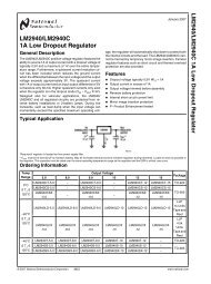
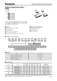
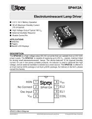
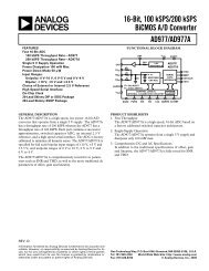
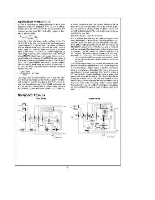
Component Layouts<br />
Split Supply<br />
If a mica insulator is used the thermal resistance will be<br />
about 16CW lubricated and 34CW dry For this example<br />
we assume a lubricated mica insulator between the<br />
<strong>LM1875</strong> and the heat sink The heat sink thermal resistance<br />
must then be less than<br />
42CWb2CWb16CWe06CW<br />
This is a rather large heat sink and may not be practical in<br />
some applications If a smaller heat sink is required for reasons<br />
of size or cost there are two alternatives The maximum<br />
ambient operating temperature can be reduced to<br />
50C (122F) resulting in a 16CW heat sink or the heat<br />
sink can be isolated from the chassis so the mica washer is<br />
not needed This will change the required heat sink to a<br />
12CW unit if the case-to-heat-sink interface is lubricated<br />
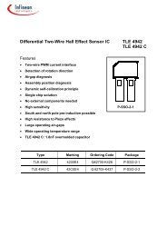
Note When using a single supply maximum transfer of heat away from the<br />
<strong>LM1875</strong> can be achieved by mounting the device directly to the heat<br />
sink (tab is at ground potential) this avoids the use of a mica or other<br />
type insulator<br />
The thermal requirements can become more difficult when<br />
an amplifier is driving a reactive load For a given magnitude<br />
of load impedance a higher degree of reactance will cause<br />
a higher level of power dissipation within the amplifier As a<br />
general rule the power dissipation of an amplifier driving a<br />
60 reactive load (usually considered to be a worst-case<br />
loudspeaker load) will be roughly that of the same amplifier<br />
driving the resistive part of that load For example a loudspeaker<br />
may at some frequency have an impedance with a<br />
magnitude of 8X and a phase angle of 60 The real part of<br />
this load will then be 4X and the amplifier power dissipation<br />
will roughly follow the curve of power dissipation with a 4X<br />
load<br />
Single Supply<br />
TLH5030–6<br />
TLH5030–7<br />
6