A Modular IGBT Converter System for High Frequency Induction ...
A Modular IGBT Converter System for High Frequency Induction ...
A Modular IGBT Converter System for High Frequency Induction ...

Create successful ePaper yourself
Turn your PDF publications into a flip-book with our unique Google optimized e-Paper software.
A <strong>Modular</strong> <strong>IGBT</strong> <strong>Converter</strong> <strong>System</strong> <strong>for</strong> <strong>High</strong> <strong>Frequency</strong> <strong>Induction</strong><br />
Heating Applications<br />
Hammad Abo Zied ; Peter Mutschler * ;Guido Bachmann<br />
Dept. of Power Electronics an Control of Drives<br />
Darmstadt University of Technology<br />
Landgraf Georg Straße 4<br />
D-64289 Darmstadt<br />
Phone: 49 6151 16-2166 Fax Phone: 49 6151 16-2613<br />
*corresponding author : pmu@srt.tu-darmstadt.de<br />
Abstract:<br />
<strong>Converter</strong>s <strong>for</strong> induction heating applications are realized up to 1.5 MW using <strong>IGBT</strong>s [3]. Switching<br />
frequencies up to 150 kHz are realized with those <strong>IGBT</strong> inverters. For special purposes it is desirable to<br />
increase the frequency up to 500 kHz. These very high switching frequencies can be achieved using<br />
MOSFETs, but this is a very costly approach due to the large silicon area of MOSFETs and problems with<br />
the internal diode of the MOSFET [11]. In many applications a galvanic isolation between the grid and the<br />
load is mandatory. This is preferably done by a high frequency trans<strong>for</strong>mer. Such induction heating plants<br />
typically are custom tailored and produced in small quantities only, resulting in high production costs.<br />
300<br />
200<br />
100<br />
100kW<br />
100kW<br />
100kW<br />
P [kW]<br />
Module<br />
100kHz<br />
Module<br />
100kHz<br />
Module<br />
100kHz<br />
Increasing output<br />
power<br />
f<br />
[kHz]<br />
100kW<br />
P [kW]<br />
Module<br />
100kHz<br />
100kW<br />
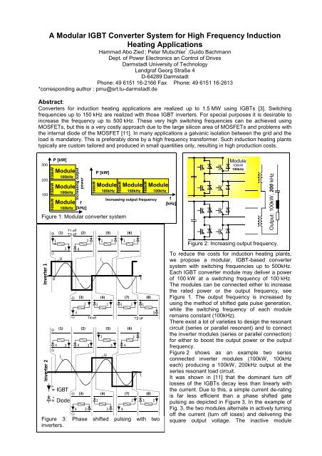
Figure 1: <strong>Modular</strong> converter system<br />
Inverter 1<br />
Inverter 2<br />
0<br />
1<br />
T1 off<br />
(1)<br />
T3 off<br />
(2)<br />
(5)<br />
u<br />
3<br />
4<br />
4<br />
(3)<br />
2<br />
1<br />
4 3 3<br />
Module<br />
100kHz<br />
100kW<br />
Increasing output frequency<br />
1 2 1 2<br />
(4) (7) (8)<br />
2 1 2 1 2 1<br />
1<br />
3<br />
4<br />
(6)<br />
(1) (2) (5) (6)<br />
4 3 4 3<br />
i<br />
^=<strong>IGBT</strong><br />
=Diode ^<br />
T4 off<br />
i<br />
u<br />
(3) (4) (7) (8)<br />
4<br />
2<br />
t<br />
T2 off<br />
t<br />
Module<br />
100kHz<br />
3<br />
2 1 2<br />
Figure 3: Phase shifted pulsing with two<br />
inverters.<br />
f<br />
[kHz]<br />
Module<br />
100kW<br />
100kHz<br />
Output: 100kW, 200 kHz<br />
Figure 2: Increasing output frequency.<br />
To reduce the costs <strong>for</strong> induction heating plants,<br />
we propose a modular, <strong>IGBT</strong>-based converter<br />
system with switching frequencies up to 500kHz.<br />
Each <strong>IGBT</strong> converter module may deliver a power<br />
of 100 kW at a switching frequency of 100 kHz.<br />
The modules can be connected either to increase<br />
the rated power or the output frequency, see<br />
Figure 1. The output frequency is increased by<br />
using the method of shifted gate pulse generation,<br />
while the switching frequency of each module<br />
remains constant (100kHz).<br />
There exist a lot of varieties to design the resonant<br />
circuit (series or parallel resonant) and to connect<br />
the inverter modules (series or parallel connection)<br />
<strong>for</strong> either to boost the output power or the output<br />
frequency.<br />
Figure 2 shows as an example two series<br />
connected inverter modules (100kW, 100kHz<br />
each) producing a 100kW, 200kHz output at the<br />
series resonant load circuit.<br />
It was shown in [11] that the dominant turn off<br />
losses of the <strong>IGBT</strong>s decay less than linearly with<br />
the current. Due to this, a simple current de-rating<br />
is far less efficient than a phase shifted gate<br />
pulsing as depicted in Figure 3. In the example of<br />
Fig. 3, the two modules alternate in actively turning<br />
off the current (turn off loses) and delivering the<br />
square output voltage. The inactive module
provides a free-wheeling path <strong>for</strong> the<br />
load current. The active switching<br />
frequency of each module is 100kHz<br />
while the resonant output frequency is<br />
200kHz. Besides the series connection of<br />
modules, a parallel connection as<br />
described in [11] is possible. Each<br />
alternative has its specific benefits.<br />
When connecting the modules in parallel,<br />
conduction losses are reduced, as the<br />
inactive modules don’t carry current.<br />
With series connection of the modules,<br />
the timing requirements <strong>for</strong> simultaneous<br />
switching in different inverter-modules<br />
appear less demanding. Investigations<br />
are necessary to find the better of the<br />
two solutions.<br />
The main challenge are the<br />
switching transients and losses. To<br />
get a first idea of the switching<br />
transients and losses, an inverter<br />
was simulated using Pspice. A<br />
Spice-model of the Eupec<br />
FF200 R 12 KS4 transistor module<br />
was used. Results are shown in Fig.<br />
4 and 5. In the simulation the gating<br />
signals were tuned <strong>for</strong> minimum<br />
losses. Fig. 4 shows, that <strong>for</strong><br />
minimum losses an overlapping<br />
conduction of both transistors in one<br />
arm will occur. The lower transistor<br />
is gated “on” during the turn-off<br />
5.86m<br />
3.91m<br />
1.95m<br />
-200A<br />
95.0us 95.2us 95.6us 96.0us 96.4us 96.8us 97.2us 97.5us<br />
IC(Z1) - IC(Z4) I(R5)<br />
Time<br />
process of the upper transistor. Fig. 5 shows the simulated losses. An experimental setup(600V DC , I AC,peak<br />
ca. 100A) is under construction now. The final paper will include measurement results and compare these<br />
with the Pspice simulation.<br />
References<br />
[1] Ying, J.: “Resonant and quasi-resonant inverters <strong>for</strong> high frequency induction heating”,<br />
Dissertation TU Berlin 1995, Verlag Dr. Köster Berlin, ISBN 3-89574-089-6<br />
0<br />
200A<br />
0A<br />
Upper transistor<br />
current<br />
[2] Dyckerhoff, S; Ryan, M; deDoncker, R.: “Design of an <strong>IGBT</strong>-based LCL-Resonant Inverter <strong>for</strong> <strong>High</strong>-<br />
<strong>Frequency</strong> <strong>Induction</strong> Heating “<br />
IEEE IAS Annual Meeting 1999 pp 2039-2045<br />
[3] Matthes, H.; Jürgens, R.: „1.6 MW 150 kHz Series Resonant Circuit <strong>Converter</strong> incorporating <strong>IGBT</strong><br />
Devices <strong>for</strong> welding applications”<br />
International <strong>Induction</strong> Heating Seminar 1998 Padova pp 25-31<br />
[4] Dede, J.; Jordan, J.; Esteve, V.; Ferreres, A.; Espi, J.: “On the Behaviour of Series and Parallel<br />
Resonant Inverters <strong>for</strong> <strong>Induction</strong> Heating under Short-Circuit Conditions”<br />
PCIM Europe 1998 Power Conversion pp 301-307<br />
[5] Dede, E. J.; Jordan, J.; Esteve V.; Navarro, A. E.; Ferreres, A.: “On the Design of a <strong>High</strong> Power <strong>IGBT</strong><br />
Series Resonant Inverter <strong>for</strong> <strong>Induction</strong> Forging Applications”<br />
IEEE 1996 AFRICON 4th pp 206-208<br />
[6] Okuno, A.; Kawano, H.; Sun, J.; Kurokawa, M.; Kojina, A.; Nakaoka, M.: „Feasible Development of<br />
Soft-Switches SIT Inverter with Load-Adaptive <strong>Frequency</strong>-Tracking Control Scheme <strong>for</strong> <strong>Induction</strong><br />
Heating”<br />
IEEE Transaction on Industry Applications, Vol. 34, no. 4, July/August 1998 pp 713-718<br />
[7] Lee, B. K.; Jung, J. W.; Suh, B. S.; Hyun, D. S.: “A New Half-Bridge Inverter Topology with Active<br />
Auxiliary Resonant Circuit Using Insulated Gate Bipolar Transistors <strong>for</strong> <strong>Induction</strong> Heating<br />
Lower transistor<br />
current<br />
400ns<br />
Load cureent<br />
Lower<br />
Transistor<br />
Current<br />
Figure 4: Simulated switching transients<br />
20KW<br />
3<br />
15KW<br />
10KW<br />
5KW<br />
>><br />
0W<br />
Energy (mJ)<br />
Energy<br />
Upper<br />
Transistor<br />
Current<br />
Load Current<br />
Figure 5: Simulated<br />
1 s(W(Z1))<br />
losses.<br />
3 W(Z1)<br />
Power (kW), Energy (mJ)<br />
Time<br />
Power<br />
95.2us 95.6us 96.0us 96.4us 96.8us 97.2us
Applications”<br />
IEEE PESC 1997 pp 1232-1237<br />
[8] Nagai, S.; Hiraki, E.; Arai, Y.; Nakaoka, M.: “New Phase-Shifted Soft-Switching PWM Series Resonant<br />
Inverter Topologies and their Practical Evaluations”<br />
IEEE International Conference on Power Electronics and Drive <strong>System</strong>s 1997 pp 318-322<br />
[9] Dede, E. J.; Jordan, J.; Esteve, V.; González, J. V.; Ramirez, D.: “Design Considerations <strong>for</strong> <strong>Induction</strong><br />
Heating Current Fed Inverters with <strong>IGBT</strong>’s Working at 100 kHz”<br />
IEEE 8 th APEC 1993 pp 679-685<br />
[10] Dawson, F. P.; Jain, P.: “ A Comparison of Load Commutated Inverter <strong>System</strong>s <strong>for</strong> <strong>Induction</strong> Heating<br />
and Melting Applications”<br />
IEEE Transactions on Power Electronics, vol. 6, no. 3, July 1991 pp 430-441<br />
[11] Undeland, T.; Kleveland, F.; Langelid, J. “Increase of Output Power from <strong>IGBT</strong>s in <strong>High</strong> Power <strong>High</strong><br />
<strong>Frequency</strong> Resonant Load Inverters”<br />
IEEE IAS Annual Meeting 2000 Roma (file 67_03.pdf)<br />
[12] Dede, E. J.; Espi J. M.; Esteve, V.; Jordán, J.; Casans, S.: “Trends in <strong>Converter</strong>s<strong>for</strong> induction heating<br />
Applications“<br />
PCIM Europe 1999 Power Conversion pp 155-160<br />
Summary:<br />
To reduce the costs <strong>for</strong> induction heating plants, we propose a modular, <strong>IGBT</strong>-based<br />
converter system with resonant output frequencies up to 500kHz. The high output<br />
frequency is achieved using a phase-shiftet gating of “n” converter modules. The<br />
switching frequency of each inverter module is 1/n of the resonant output. Pspice<br />
simulations of the switching transients will be compared with experimental results.