

Survey of Blunt Body Dynamic Stability in Supersonic Flow
Survey of Blunt Body Dynamic Stability in Supersonic Flow
Survey of Blunt Body Dynamic Stability in Supersonic Flow

Create successful ePaper yourself
Turn your PDF publications into a flip-book with our unique Google optimized e-Paper software.
As the focus changed from ballistic missiles to blunt<br />
capsule shapes with the rise <strong>of</strong> the space race, it<br />
became clear that an understand<strong>in</strong>g <strong>of</strong> the aftbody<br />
flow structure was critical to understand<strong>in</strong>g the<br />
dynamic stability phenomenon.<br />
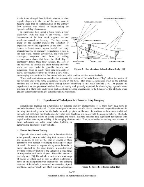
In supersonic flow about a blunt body, a bow<br />
shockwave leads the nose <strong>of</strong> the vehicle. <strong>Flow</strong><br />
downstream <strong>of</strong> the bow shock stagnates on and<br />
accelerates around the forebody. The large turn<strong>in</strong>g<br />
angle <strong>of</strong>f the shoulder <strong>in</strong>duces the formation <strong>of</strong><br />
expansion waves and separation <strong>of</strong> the flow. This<br />
creates a low-pressure region beh<strong>in</strong>d the body<br />
characterized by an unsteady recirculation region <strong>in</strong><br />
the near wake. Further downstream, the wake flow<br />
converges, stagnates and forms a trail<strong>in</strong>g<br />
recompression shock that heats the fluid. Fig. 3<br />
graphically depicts these flow features. The core <strong>of</strong><br />
the wake will be viscous and <strong>of</strong>ten partially subsonic<br />
while the outer wake is typically <strong>in</strong>viscid and<br />
supersonic. Even <strong>in</strong> steady flight with zero angle <strong>of</strong><br />
Figure 3. <strong>Flow</strong> structure beh<strong>in</strong>d a blunt body [18]<br />
attack, these factors comb<strong>in</strong>e to result <strong>in</strong> a flow with a<br />
time-vary<strong>in</strong>g pressure field is a function <strong>of</strong> axial and radial position relative to the forebody.<br />
When pitch oscillations are added to this scenario, the position <strong>of</strong> the wake features “lag” beh<strong>in</strong>d the motion <strong>of</strong><br />
the forebody due to the f<strong>in</strong>ite convection velocity <strong>in</strong> the flow. This creates a hysteresis effect on the pitch<strong>in</strong>g<br />
moment and aft body pressure field, add<strong>in</strong>g further complexity to the wake structure [19]. At present, no<br />
experimental or computational methods have accurately and generally captured the time-vary<strong>in</strong>g, dynamic wake<br />
structure <strong>of</strong> a blunt body undergo<strong>in</strong>g pitch oscillations. Large uncerta<strong>in</strong>ties <strong>in</strong> the behavior <strong>of</strong> the aft body wake<br />
prevent a clear understand<strong>in</strong>g <strong>of</strong> dynamic stability phenomena.<br />
II.<br />
Experimental Techniques for Characteriz<strong>in</strong>g Damp<strong>in</strong>g<br />
Experimental methods for determ<strong>in</strong><strong>in</strong>g the dynamic stability characteristics <strong>of</strong> a blunt body have roots <strong>in</strong><br />
methods developed for aircraft. Captive techniques <strong>in</strong>volve the use <strong>of</strong> a classic w<strong>in</strong>d tunnel setup with variations <strong>in</strong><br />
the st<strong>in</strong>g functionality such that the body can undergo pitch oscillations. In addition to these more traditional<br />
methods, sub scale free flight techniques have also been developed which can yield the damp<strong>in</strong>g behavior <strong>of</strong> a body<br />
without the <strong>in</strong>trusive effects <strong>of</strong> a st<strong>in</strong>g tarnish<strong>in</strong>g the results. Exist<strong>in</strong>g methods have significant deficiencies with<br />
regard to either accuracy or validity <strong>of</strong> the damp<strong>in</strong>g characteristics. Thus, to m<strong>in</strong>imize uncerta<strong>in</strong>ty, two or more <strong>of</strong><br />
these techniques are <strong>of</strong>ten used when build<strong>in</strong>g an<br />
aerodynamic database <strong>of</strong> a new vehicle.<br />
A. Forced Oscillation Test<strong>in</strong>g<br />
<strong>Dynamic</strong> w<strong>in</strong>d tunnel test<strong>in</strong>g with a forced oscillation<br />
setup generally uses an axial st<strong>in</strong>g that measures forces<br />
and moments, as well as the rates <strong>of</strong> change <strong>of</strong> these<br />
parameters with respect to chang<strong>in</strong>g pitch angle or angle<br />
<strong>of</strong> attack. In order to capture the dynamic behavior, a<br />
motor attached to the st<strong>in</strong>g imparts a one-degree-<strong>of</strong>freedom<br />
oscillatory motion to the vehicle at a wide range<br />
<strong>of</strong> frequencies and mode shapes. S<strong>in</strong>usoidal motion is<br />
typically used [20]. The vehicle is <strong>in</strong>cl<strong>in</strong>ed at a wide range<br />
<strong>of</strong> angles <strong>of</strong> attack and at each condition undergoes a<br />
series <strong>of</strong> small amplitude pitch oscillations. The damp<strong>in</strong>g<br />
response <strong>of</strong> the vehicle is measured as a function <strong>of</strong> pitch<br />
amplitude, angle <strong>of</strong> attack, and Mach number. Advantages<br />
Figure 4. Forced oscillation setup [22]<br />
5 <strong>of</strong> 27<br />
American Institute <strong>of</strong> Aeronautics and Astronautics


