Examination of the intact stability and the seakeeping behaviour
Examination of the intact stability and the seakeeping behaviour
Examination of the intact stability and the seakeeping behaviour

You also want an ePaper? Increase the reach of your titles
YUMPU automatically turns print PDFs into web optimized ePapers that Google loves.
Dezember 2010<br />
SCHRIFTENREIHE SCHIFFBAU<br />
Nicolas Rox<br />
<strong>Examination</strong> <strong>of</strong> <strong>the</strong> <strong>intact</strong> <strong>stability</strong> <strong>and</strong><br />
<strong>the</strong> <strong>seakeeping</strong> <strong>behaviour</strong> <strong>of</strong> container<br />
vessels within <strong>the</strong> ballast condition
DIPLOMARBEIT<br />
für Herrn c<strong>and</strong>. arch. nav. Nicolas Rox<br />
Matr.-Nr. 25794<br />
<strong>Examination</strong> <strong>of</strong> <strong>the</strong> <strong>intact</strong> <strong>stability</strong> <strong>and</strong> <strong>the</strong> <strong>seakeeping</strong> <strong>behaviour</strong> <strong>of</strong><br />
container vessels within <strong>the</strong> ballast condition<br />
The scope <strong>of</strong> this <strong>the</strong>sis is to examine, if <strong>the</strong> ballast condition <strong>of</strong> container vessels is<br />
supposed to be a seagoing condition or if <strong>the</strong>re is an increased risk <strong>of</strong> accident in this<br />
case due to <strong>the</strong> design <strong>of</strong> this specific ship type.<br />
For this reason Nicolas Rox is asked to examine <strong>the</strong> <strong>intact</strong> <strong>stability</strong> <strong>and</strong> <strong>the</strong><br />
<strong>seakeeping</strong> <strong>behaviour</strong> <strong>of</strong> various sized container vessels within <strong>the</strong> ballast condition<br />
for situations that have led to accidents with this ship type as is known. The<br />
examination is supposed to be done based on computer models which exist at <strong>the</strong><br />
Institute <strong>of</strong> Ship Design <strong>and</strong> Ship Safety at <strong>the</strong> Hamburg University <strong>of</strong> Technology,<br />
whereas <strong>the</strong> loading conditions should be according to <strong>the</strong> issued <strong>stability</strong> booklets.<br />
Finally approaches to reduce <strong>the</strong> risk <strong>of</strong> accident shall be provided!<br />
Beginn der Arbeit: 04. August 2010<br />
Abgabe der Arbeit: 03. Dezember 2010<br />
Hamburg, 04. August 2010<br />
____________________<br />
Pr<strong>of</strong>. Dr.-Ing. S. Krüger<br />
Postanschrift: Telefon: E-mail:<br />
Pr<strong>of</strong>. Dr.-Ing. Stefan Krüger ++49 (40) 428 78 - 6105 krueger@tu-harburg.de<br />
Inst. für Entwerfen von Schiffen und Schiffssicherheit Fax: www.ssi.tu-harburg.de<br />
Schwarzenbergstraße 95, Gebäude C ++49 (40) 428 78 - 6139<br />
D - 21073 Hamburg
1st Examiner: Pr<strong>of</strong>. Dr.-Ing. Stefan Krüger<br />
2nd Examiner: Pr<strong>of</strong>. Dr.-Ing. Moustafa Abdel-Maksoud<br />
December 2010
I hereby declare <strong>and</strong> conrm that this <strong>the</strong>sis is entirely <strong>the</strong> result <strong>of</strong> my own work. I did not<br />
utilise any o<strong>the</strong>r sources <strong>and</strong> appliances than those specied in <strong>the</strong> bibliography.
Contents<br />
List <strong>of</strong> Figures<br />
List <strong>of</strong> Tables<br />
V<br />
VII<br />
1 Introduction 1<br />
1.1 Key data <strong>of</strong> <strong>the</strong> three examined accidents . . . . . . . . . . . . . . . . . . . . . . 1<br />
1.1.1 Accident <strong>of</strong> <strong>the</strong> CMS Chicago Express [1] . . . . . . . . . . . . . . . . 1<br />
1.1.2 Accident <strong>of</strong> a 2468 TEU container vessel [2] . . . . . . . . . . . . . . . . 2<br />
1.1.3 Accident <strong>of</strong> a 2500 TEU container vessel [3] . . . . . . . . . . . . . . . . 2<br />
1.2 Following objectives for <strong>the</strong> diploma <strong>the</strong>sis . . . . . . . . . . . . . . . . . . . . . . 3<br />
2 Theory 5<br />
2.1 Description <strong>of</strong> <strong>the</strong> utilised <strong>seakeeping</strong> simulation method . . . . . . . . . . . . . 5<br />
2.1.1 Linear strip method . . . . . . . . . . . . . . . . . . . . . . . . . . . . . . 5<br />
2.1.1.1 Calculation model . . . . . . . . . . . . . . . . . . . . . . . . . . 5<br />
2.1.1.2 Roll radius <strong>of</strong> inertia <strong>and</strong> roll period . . . . . . . . . . . . . . . . 6<br />
2.1.1.3 Roll damping . . . . . . . . . . . . . . . . . . . . . . . . . . . . . 6<br />
2.1.1.4 Calculation settings . . . . . . . . . . . . . . . . . . . . . . . . . 7<br />
2.1.1.5 Typical RAOs . . . . . . . . . . . . . . . . . . . . . . . . . . . . 8<br />
2.1.2 Nonlinear <strong>seakeeping</strong> . . . . . . . . . . . . . . . . . . . . . . . . . . . . . . 8<br />
2.1.2.1 Roll motion . . . . . . . . . . . . . . . . . . . . . . . . . . . . . . 9<br />
2.1.2.2 Surge Motion . . . . . . . . . . . . . . . . . . . . . . . . . . . . . 9<br />
2.1.3 Conclusion . . . . . . . . . . . . . . . . . . . . . . . . . . . . . . . . . . . 10<br />
2.2 Environmental conditions . . . . . . . . . . . . . . . . . . . . . . . . . . . . . . . 10<br />
2.2.1 Sea condition . . . . . . . . . . . . . . . . . . . . . . . . . . . . . . . . . . 10<br />
2.2.2 Wind condition . . . . . . . . . . . . . . . . . . . . . . . . . . . . . . . . . 11<br />
3 Data input 13<br />
3.1 Main Dimensions . . . . . . . . . . . . . . . . . . . . . . . . . . . . . . . . . . . . 13<br />
3.2 Lines <strong>of</strong> <strong>the</strong> ship . . . . . . . . . . . . . . . . . . . . . . . . . . . . . . . . . . . . 13<br />
3.3 Lateral areas . . . . . . . . . . . . . . . . . . . . . . . . . . . . . . . . . . . . . . 13<br />
3.4 Lightship distribution . . . . . . . . . . . . . . . . . . . . . . . . . . . . . . . . . 14<br />
3.5 Loading condition . . . . . . . . . . . . . . . . . . . . . . . . . . . . . . . . . . . . 14<br />
3.6 Free surface correction . . . . . . . . . . . . . . . . . . . . . . . . . . . . . . . . . 15<br />
3.7 Intact <strong>stability</strong> . . . . . . . . . . . . . . . . . . . . . . . . . . . . . . . . . . . . . 15<br />
3.8 Cross-curves <strong>of</strong> <strong>stability</strong> . . . . . . . . . . . . . . . . . . . . . . . . . . . . . . . . 15<br />
3.9 Bilge keel dimensions . . . . . . . . . . . . . . . . . . . . . . . . . . . . . . . . . . 16<br />
3.10 Bridge height . . . . . . . . . . . . . . . . . . . . . . . . . . . . . . . . . . . . . . 17<br />
3.11 Size range <strong>of</strong> <strong>the</strong> examined vessels . . . . . . . . . . . . . . . . . . . . . . . . . . 18<br />
3.12 Sea conditions to be examined . . . . . . . . . . . . . . . . . . . . . . . . . . . . . 18<br />
4 <strong>Examination</strong> 19<br />
4.1 Vessel No. 01 . . . . . . . . . . . . . . . . . . . . . . . . . . . . . . . . . . . . . 19<br />
I
Contents<br />
4.2 Vessel No. 02 . . . . . . . . . . . . . . . . . . . . . . . . . . . . . . . . . . . . . 21<br />
4.3 Vessel No. 03 . . . . . . . . . . . . . . . . . . . . . . . . . . . . . . . . . . . . . 22<br />
4.4 Vessel No. 04 . . . . . . . . . . . . . . . . . . . . . . . . . . . . . . . . . . . . . 24<br />
4.5 Vessel No. 05 . . . . . . . . . . . . . . . . . . . . . . . . . . . . . . . . . . . . . 25<br />
4.6 Vessel No. 06 . . . . . . . . . . . . . . . . . . . . . . . . . . . . . . . . . . . . . 27<br />
4.7 Vessel No. 07 . . . . . . . . . . . . . . . . . . . . . . . . . . . . . . . . . . . . . 28<br />
4.8 Vessel No. 08 . . . . . . . . . . . . . . . . . . . . . . . . . . . . . . . . . . . . . 30<br />
4.9 Vessel No. 09 . . . . . . . . . . . . . . . . . . . . . . . . . . . . . . . . . . . . . 31<br />
4.10 Vessel No. 10 . . . . . . . . . . . . . . . . . . . . . . . . . . . . . . . . . . . . . 33<br />
4.11 Vessel No. 11 . . . . . . . . . . . . . . . . . . . . . . . . . . . . . . . . . . . . . 34<br />
4.12 Vessel No. 12 . . . . . . . . . . . . . . . . . . . . . . . . . . . . . . . . . . . . . 36<br />
4.13 Vessel No. 13 . . . . . . . . . . . . . . . . . . . . . . . . . . . . . . . . . . . . . 37<br />
4.14 Vessel No. 14 . . . . . . . . . . . . . . . . . . . . . . . . . . . . . . . . . . . . . 39<br />
4.15 Vessel No. 15 . . . . . . . . . . . . . . . . . . . . . . . . . . . . . . . . . . . . . 41<br />
5 Evaluation 43<br />
5.1 Results . . . . . . . . . . . . . . . . . . . . . . . . . . . . . . . . . . . . . . . . . . 43<br />
5.2 Consequences . . . . . . . . . . . . . . . . . . . . . . . . . . . . . . . . . . . . . . 44<br />
5.3 Recommendations . . . . . . . . . . . . . . . . . . . . . . . . . . . . . . . . . . . 45<br />
5.3.1 Stability . . . . . . . . . . . . . . . . . . . . . . . . . . . . . . . . . . . . . 45<br />
5.3.2 Roll damping . . . . . . . . . . . . . . . . . . . . . . . . . . . . . . . . . . 45<br />
5.3.3 Lines <strong>of</strong> <strong>the</strong> ship . . . . . . . . . . . . . . . . . . . . . . . . . . . . . . . . 46<br />
5.3.4 O<strong>the</strong>r . . . . . . . . . . . . . . . . . . . . . . . . . . . . . . . . . . . . . . 46<br />
6 Detailed examination 47<br />
6.1 Variation <strong>of</strong> <strong>the</strong> GM values . . . . . . . . . . . . . . . . . . . . . . . . . . . . . . 47<br />
6.1.1 Small vessel . . . . . . . . . . . . . . . . . . . . . . . . . . . . . . . . . . . 47<br />
6.1.2 Midsized vessel . . . . . . . . . . . . . . . . . . . . . . . . . . . . . . . . . 48<br />
6.1.3 Large vessel . . . . . . . . . . . . . . . . . . . . . . . . . . . . . . . . . . . 49<br />
6.1.4 Comparison <strong>of</strong> <strong>the</strong> simulation results . . . . . . . . . . . . . . . . . . . . . 50<br />
6.2 Rolling behavior <strong>of</strong> <strong>the</strong> large vessels . . . . . . . . . . . . . . . . . . . . . . . . . . 51<br />
6.2.1 Large Vessel No. 15 . . . . . . . . . . . . . . . . . . . . . . . . . . . . . 52<br />
6.2.2 Large Vessel No. 11 . . . . . . . . . . . . . . . . . . . . . . . . . . . . . 53<br />
7 Conclusions 57<br />
A Vessel data 59<br />
A.1 Vessel No. 01 . . . . . . . . . . . . . . . . . . . . . . . . . . . . . . . . . . . . . 59<br />
A.2 Vessel No. 02 . . . . . . . . . . . . . . . . . . . . . . . . . . . . . . . . . . . . . 60<br />
A.3 Vessel No. 03 . . . . . . . . . . . . . . . . . . . . . . . . . . . . . . . . . . . . . 61<br />
A.4 Vessel No. 04 . . . . . . . . . . . . . . . . . . . . . . . . . . . . . . . . . . . . . 62<br />
A.5 Vessel No. 05 . . . . . . . . . . . . . . . . . . . . . . . . . . . . . . . . . . . . . 63<br />
A.6 Vessel No. 06 . . . . . . . . . . . . . . . . . . . . . . . . . . . . . . . . . . . . . 64<br />
A.7 Vessel No. 07 . . . . . . . . . . . . . . . . . . . . . . . . . . . . . . . . . . . . . 65<br />
A.8 Vessel No. 08 . . . . . . . . . . . . . . . . . . . . . . . . . . . . . . . . . . . . . 66<br />
A.9 Vessel No. 09 . . . . . . . . . . . . . . . . . . . . . . . . . . . . . . . . . . . . . 67<br />
A.10 Vessel No. 10 . . . . . . . . . . . . . . . . . . . . . . . . . . . . . . . . . . . . . 68<br />
A.11 Vessel No. 11 . . . . . . . . . . . . . . . . . . . . . . . . . . . . . . . . . . . . . 69<br />
A.12 Vessel No. 12 . . . . . . . . . . . . . . . . . . . . . . . . . . . . . . . . . . . . . 70<br />
A.13 Vessel No. 13 . . . . . . . . . . . . . . . . . . . . . . . . . . . . . . . . . . . . . 71<br />
II
Contents<br />
A.14 Vessel No. 14 . . . . . . . . . . . . . . . . . . . . . . . . . . . . . . . . . . . . . 72<br />
A.15 Vessel No. 15 . . . . . . . . . . . . . . . . . . . . . . . . . . . . . . . . . . . . . 73<br />
B Variation <strong>of</strong> <strong>the</strong> bilge keel area 75<br />
C Variation <strong>of</strong> <strong>the</strong> ship's speed 77<br />
Bibliography 79<br />
III
Contents<br />
IV
List <strong>of</strong> Figures<br />
2.1 Calculation model for <strong>the</strong> RAO determination . . . . . . . . . . . . . . . . . . . . 6<br />
2.2 Typical RAOs . . . . . . . . . . . . . . . . . . . . . . . . . . . . . . . . . . . . . . 8<br />
2.3 Jonswap spectrum for H 1/3 = 7, 5 m <strong>and</strong> T p = 11 s . . . . . . . . . . . . . . . . . 11<br />
3.1 Lines plan <strong>of</strong> one <strong>of</strong> <strong>the</strong> examined vessels . . . . . . . . . . . . . . . . . . . . . . . 13<br />
3.2 Lightship distribution <strong>of</strong> one <strong>of</strong> <strong>the</strong> examined vessels . . . . . . . . . . . . . . . . 14<br />
3.3 Bilge keel area distribution . . . . . . . . . . . . . . . . . . . . . . . . . . . . . . 16<br />
3.4 Bridge height above ballast arrival waterline . . . . . . . . . . . . . . . . . . . . . 17<br />
3.5 Vessels size range . . . . . . . . . . . . . . . . . . . . . . . . . . . . . . . . . . . . 18<br />
4.1 Lines plan <strong>and</strong> lateral areas <strong>of</strong> Vessel No. 01 . . . . . . . . . . . . . . . . . . . . 19<br />
4.2 Transversal acceleration on <strong>the</strong> bridge <strong>of</strong> Vessel No. 01 in accident situation 3 . 20<br />
4.3 Lines plan <strong>and</strong> lateral areas <strong>of</strong> Vessel No. 02 . . . . . . . . . . . . . . . . . . . . 21<br />
4.4 Transversal acceleration on <strong>the</strong> bridge <strong>of</strong> Vessel No. 02 in accident situation 3 . 22<br />
4.5 Lines plan <strong>and</strong> lateral areas <strong>of</strong> Vessel No. 03 . . . . . . . . . . . . . . . . . . . . 22<br />
4.6 Transversal acceleration on <strong>the</strong> bridge <strong>of</strong> Vessel No. 03 in accident situation 3 . 23<br />
4.7 Lines plan <strong>and</strong> lateral areas <strong>of</strong> Vessel No. 04 . . . . . . . . . . . . . . . . . . . . 24<br />
4.8 Transversal acceleration on <strong>the</strong> bridge <strong>of</strong> Vessel No. 04 in accident situation 3 . 25<br />
4.9 Lines plan <strong>and</strong> lateral areas <strong>of</strong> Vessel No. 05 . . . . . . . . . . . . . . . . . . . . 25<br />
4.10 Transversal acceleration on <strong>the</strong> bridge <strong>of</strong> Vessel No. 05 in accident situation 2 . 26<br />
4.11 Lines plan <strong>and</strong> lateral areas <strong>of</strong> Vessel No. 06 . . . . . . . . . . . . . . . . . . . . 27<br />
4.12 Transversal acceleration on <strong>the</strong> bridge <strong>of</strong> Vessel No. 06 in accident situation 3 . 28<br />
4.13 Lines plan <strong>and</strong> lateral areas <strong>of</strong> Vessel No. 07 . . . . . . . . . . . . . . . . . . . . 28<br />
4.14 Transversal acceleration on <strong>the</strong> bridge <strong>of</strong> Vessel No. 07 in accident situation 3 . 29<br />
4.15 Lines plan <strong>and</strong> lateral areas <strong>of</strong> Vessel No. 08 . . . . . . . . . . . . . . . . . . . . 30<br />
4.16 Transversal acceleration on <strong>the</strong> bridge <strong>of</strong> Vessel No. 08 in accident situation 3 . 31<br />
4.17 Lines plan <strong>and</strong> lateral areas <strong>of</strong> Vessel No. 09 . . . . . . . . . . . . . . . . . . . . 31<br />
4.18 Transversal acceleration on <strong>the</strong> bridge <strong>of</strong> Vessel No. 09 in accident situation 3 . 32<br />
4.19 Lines plan <strong>and</strong> lateral areas <strong>of</strong> Vessel No. 10 . . . . . . . . . . . . . . . . . . . . 33<br />
4.20 Transversal acceleration on <strong>the</strong> bridge <strong>of</strong> Vessel No. 10 in accident situation 2 . 34<br />
4.21 Lines plan <strong>and</strong> lateral areas <strong>of</strong> Vessel No. 11 . . . . . . . . . . . . . . . . . . . . 34<br />
4.22 Transversal acceleration on <strong>the</strong> bridge <strong>of</strong> Vessel No. 11 in accident situation 3 . 35<br />
4.23 Lines plan <strong>and</strong> lateral areas <strong>of</strong> Vessel No. 12 . . . . . . . . . . . . . . . . . . . . 36<br />
4.24 Transversal acceleration on <strong>the</strong> bridge <strong>of</strong> Vessel No. 12 in accident situation 3 . 37<br />
4.25 Lines plan <strong>and</strong> lateral areas <strong>of</strong> Vessel No. 13 . . . . . . . . . . . . . . . . . . . . 37<br />
4.26 Transversal acceleration on <strong>the</strong> bridge <strong>of</strong> Vessel No. 13 in accident situation 2 . 38<br />
4.27 Lines plan <strong>and</strong> lateral areas <strong>of</strong> Vessel No. 14 . . . . . . . . . . . . . . . . . . . . 39<br />
4.28 Transversal acceleration on <strong>the</strong> bridge <strong>of</strong> Vessel No. 14 in accident situation 2 . 40<br />
4.29 Lines plan <strong>and</strong> lateral areas <strong>of</strong> Vessel No. 15 . . . . . . . . . . . . . . . . . . . . 41<br />
4.30 Transversal acceleration on <strong>the</strong> bridge <strong>of</strong> Vessel No. 15 in accident situation 3 . 42<br />
5.1 Transversal accelerations on <strong>the</strong> bridge against GM solid . . . . . . . . . . . . . . . 44<br />
V
List <strong>of</strong> Figures<br />
6.1 Vessel No. 13 in ballast arrival oating condition: Variation <strong>of</strong> GM solid . . . . 48<br />
6.2 Vessel No. 01 in ballast arrival oating condition: Variation <strong>of</strong> GM solid . . . . 49<br />
6.3 Chicago Express in ballast arrival oating condition: Variation <strong>of</strong> GM solid . . 50<br />
6.4 Comparison <strong>of</strong> <strong>the</strong> <strong>stability</strong> inuence for <strong>the</strong> three vessels in accident situation 1 51<br />
6.5 Vessel No. 15: Variation <strong>of</strong> GM solid in CE alike loading condition . . . . . . . 53<br />
6.6 Vessel No. 11: Variation <strong>of</strong> GM solid in dierent loading conditions . . . . . . . 55<br />
B.1 Vessel No. 13 in ballast arrival loading condition; Variation <strong>of</strong> <strong>the</strong> bilge keel<br />
area; Accident situation 2 . . . . . . . . . . . . . . . . . . . . . . . . . . . . . . . 75<br />
C.1 Vessel No. 13 in ballast arrival loading condition; Variation <strong>of</strong> ship's speed; Sea<br />
conditions <strong>of</strong> accident situation 2 . . . . . . . . . . . . . . . . . . . . . . . . . . . 77<br />
VI
List <strong>of</strong> Tables<br />
3.1 Accident situations . . . . . . . . . . . . . . . . . . . . . . . . . . . . . . . . . . . 18<br />
4.1 Main dimensions <strong>of</strong> Vessel No. 01 . . . . . . . . . . . . . . . . . . . . . . . . . . 19<br />
4.2 Results <strong>of</strong> <strong>the</strong> <strong>seakeeping</strong> calculation for Vessel No. 01 . . . . . . . . . . . . . . 20<br />
4.3 Main dimensions <strong>of</strong> Vessel No. 02 . . . . . . . . . . . . . . . . . . . . . . . . . . 21<br />
4.4 Results <strong>of</strong> <strong>the</strong> <strong>seakeeping</strong> calculation for Vessel No. 02 . . . . . . . . . . . . . . 21<br />
4.5 Main dimensions <strong>of</strong> Vessel No. 03 . . . . . . . . . . . . . . . . . . . . . . . . . . 22<br />
4.6 Results <strong>of</strong> <strong>the</strong> <strong>seakeeping</strong> calculation for Vessel No. 03 . . . . . . . . . . . . . . 23<br />
4.7 Main dimensions <strong>of</strong> Vessel No. 04 . . . . . . . . . . . . . . . . . . . . . . . . . . 24<br />
4.8 Results <strong>of</strong> <strong>the</strong> <strong>seakeeping</strong> calculation for Vessel No. 04 . . . . . . . . . . . . . . 24<br />
4.9 Main dimensions <strong>of</strong> Vessel No. 05 . . . . . . . . . . . . . . . . . . . . . . . . . . 25<br />
4.10 Results <strong>of</strong> <strong>the</strong> <strong>seakeeping</strong> calculation for Vessel No. 05 . . . . . . . . . . . . . . 26<br />
4.11 Main dimensions <strong>of</strong> Vessel No. 06 . . . . . . . . . . . . . . . . . . . . . . . . . . 27<br />
4.12 Results <strong>of</strong> <strong>the</strong> <strong>seakeeping</strong> calculation for Vessel No. 06 . . . . . . . . . . . . . . 27<br />
4.13 Main dimensions <strong>of</strong> Vessel No. 07 . . . . . . . . . . . . . . . . . . . . . . . . . . 28<br />
4.14 Results <strong>of</strong> <strong>the</strong> <strong>seakeeping</strong> calculation for Vessel No. 07 . . . . . . . . . . . . . . 29<br />
4.15 Main dimensions <strong>of</strong> Vessel No. 08 . . . . . . . . . . . . . . . . . . . . . . . . . . 30<br />
4.16 Results <strong>of</strong> <strong>the</strong> <strong>seakeeping</strong> calculation for Vessel No. 08 . . . . . . . . . . . . . . 30<br />
4.17 Main dimensions <strong>of</strong> Vessel No. 09 . . . . . . . . . . . . . . . . . . . . . . . . . . 31<br />
4.18 Results <strong>of</strong> <strong>the</strong> <strong>seakeeping</strong> calculation for Vessel No. 09 . . . . . . . . . . . . . . 32<br />
4.19 Main dimensions <strong>of</strong> Vessel No. 10 . . . . . . . . . . . . . . . . . . . . . . . . . . 33<br />
4.20 Results <strong>of</strong> <strong>the</strong> <strong>seakeeping</strong> calculation for Vessel No. 10 . . . . . . . . . . . . . . 33<br />
4.21 Main dimensions <strong>of</strong> Vessel No. 11 . . . . . . . . . . . . . . . . . . . . . . . . . . 34<br />
4.22 Results <strong>of</strong> <strong>the</strong> <strong>seakeeping</strong> calculation for Vessel No. 11 . . . . . . . . . . . . . . 35<br />
4.23 Main dimensions <strong>of</strong> Vessel No. 12 . . . . . . . . . . . . . . . . . . . . . . . . . . 36<br />
4.24 Results <strong>of</strong> <strong>the</strong> <strong>seakeeping</strong> calculation for Vessel No. 12 . . . . . . . . . . . . . . 36<br />
4.25 Main dimensions <strong>of</strong> Vessel No. 13 . . . . . . . . . . . . . . . . . . . . . . . . . . 37<br />
4.26 Results <strong>of</strong> <strong>the</strong> <strong>seakeeping</strong> calculation for Vessel No. 13 . . . . . . . . . . . . . . 38<br />
4.27 Main dimensions <strong>of</strong> Vessel No. 14 . . . . . . . . . . . . . . . . . . . . . . . . . . 39<br />
4.28 Results <strong>of</strong> <strong>the</strong> <strong>seakeeping</strong> calculation for Vessel No. 14 . . . . . . . . . . . . . . 39<br />
4.29 Main dimensions <strong>of</strong> Vessel No. 15 . . . . . . . . . . . . . . . . . . . . . . . . . . 41<br />
4.30 Results <strong>of</strong> <strong>the</strong> <strong>seakeeping</strong> calculation for Vessel No. 15 . . . . . . . . . . . . . . 41<br />
6.1 Stability data for <strong>the</strong> small vessel . . . . . . . . . . . . . . . . . . . . . . . . . . 48<br />
6.2 Stability data for <strong>the</strong> midsized vessel . . . . . . . . . . . . . . . . . . . . . . . . . 49<br />
6.3 Stability data for <strong>the</strong> large vessel . . . . . . . . . . . . . . . . . . . . . . . . . . . 50<br />
6.4 Loading condition <strong>of</strong> <strong>the</strong> Chicago Express during its accident . . . . . . . . . 52<br />
6.5 Vessel No. 15: CE alike oating condition . . . . . . . . . . . . . . . . . . . . . 52<br />
6.6 Vessel No. 15: Transversal accelerations for CE alike loading conditions . . . . 53<br />
6.7 Vessel No. 11: Chicago Express alike oating condition . . . . . . . . . . . . 54<br />
6.8 Vessel No. 11: Transversal accelerations for CE alike loading conditions . . . . 54<br />
6.9 Vessel No. 11: New oating condition . . . . . . . . . . . . . . . . . . . . . . . 54<br />
VII
List <strong>of</strong> Tables<br />
6.10 Vessel No. 11: Transversal accelerations for new loading conditions . . . . . . . 55<br />
A.1 Detailed main dimensions, Vessel No. 01 . . . . . . . . . . . . . . . . . . . . . . 59<br />
A.2 Detailed main dimensions, Vessel No. 02 . . . . . . . . . . . . . . . . . . . . . . 60<br />
A.3 Detailed main dimensions, Vessel No. 03 . . . . . . . . . . . . . . . . . . . . . . 61<br />
A.4 Detailed main dimensions, Vessel No. 04 . . . . . . . . . . . . . . . . . . . . . . 62<br />
A.5 Detailed main dimensions, Vessel No. 05 . . . . . . . . . . . . . . . . . . . . . . 63<br />
A.6 Detailed main dimensions, Vessel No. 06 . . . . . . . . . . . . . . . . . . . . . . 64<br />
A.7 Detailed main dimensions, Vessel No. 07 . . . . . . . . . . . . . . . . . . . . . . 65<br />
A.8 Detailed main dimensions, Vessel No. 08 . . . . . . . . . . . . . . . . . . . . . . 66<br />
A.9 Detailed main dimensions, Vessel No. 09 . . . . . . . . . . . . . . . . . . . . . . 67<br />
A.10 Detailed main dimensions, Vessel No. 10 . . . . . . . . . . . . . . . . . . . . . . 68<br />
A.11 Detailed main dimensions, Vessel No. 11 . . . . . . . . . . . . . . . . . . . . . . 69<br />
A.12 Detailed main dimensions, Vessel No. 12 . . . . . . . . . . . . . . . . . . . . . . 70<br />
A.13 Detailed main dimensions, Vessel No. 13 . . . . . . . . . . . . . . . . . . . . . . 71<br />
A.14 Detailed main dimensions, Vessel No. 14 . . . . . . . . . . . . . . . . . . . . . . 72<br />
A.15 Detailed main dimensions, Vessel No. 15 . . . . . . . . . . . . . . . . . . . . . . 73<br />
VIII
Nomenclature<br />
Symbol Unit Meaning<br />
A BK<br />
[<br />
m<br />
2 ] Total bilge keel area<br />
a t max [ m /s 2 ] Maximum occurring transversal acceleration<br />
B [m] Ship's breadth<br />
c B [−] Block coecient<br />
D [m] Depth to freeboard deck<br />
△ [t] Displacement <strong>of</strong> <strong>the</strong> ship<br />
g [ m /s 2 ] Gravitational acceleration which is 9.81 m /s 2<br />
GM corrected [m] Metacentric height with free surface correction<br />
GM solid [m] Metacentric height without free surface correction<br />
GZ [m] Righting lever<br />
H 1/3 [m] Signicant wave height<br />
KG [m] Vertical center <strong>of</strong> gravity<br />
L OA [m] Length over all<br />
L P P [m] Length between <strong>the</strong> perpendiculars<br />
ϕ max [ ◦ ] Maximum occurring rolling angle<br />
T D [m] Design draft<br />
T P [s] Peak wave period<br />
T S [s] Signicant wave period<br />
v [kts] Ship's speed<br />
Abbreviation<br />
Meaning<br />
a. B.L. above baseline<br />
AP<br />
After Perpendicular<br />
BSU<br />
Bundesstelle für Seeunfalluntersuchung; Federal Bureau <strong>of</strong> Maritime<br />
Casualty Investigation<br />
DNV Det Norske Veritas<br />
E4<br />
A method database for ship design<br />
FP<br />
Forward Perpendicular<br />
HSVA Hamburgische Schibau- Versuchs Anstalt<br />
IMO<br />
International Maritime Organisation<br />
PRADS International symposium on PRActical Design <strong>and</strong> o<strong>the</strong>r oating<br />
Structures<br />
RAO Response Amplitude Operator<br />
TEU<br />
Twenty feet Equivalent Unit<br />
TUHH Technische Universität Hamburg-Harburg; Hamburg University <strong>of</strong><br />
Technology<br />
IX
List <strong>of</strong> Tables<br />
X
1 Introduction<br />
In <strong>the</strong> years 2008/2009 <strong>the</strong> world economic crisis caused a reduction in <strong>the</strong> number <strong>of</strong> transported<br />
TEU, due to a signicant decrease in transported goods. Consequently a great number <strong>of</strong> container<br />
vessels had been laid up or were forced to operate with a small amount <strong>of</strong> cargo on board.<br />
In this loading condition container vessels have a very high <strong>stability</strong>. In many cases <strong>the</strong>ir vertical<br />
center <strong>of</strong> gravity is even located below <strong>the</strong> lightship condition's coordinate. This is due to large<br />
amounts <strong>of</strong> ballast water in wing <strong>and</strong> double bottom tanks as well as no or only a small amount<br />
<strong>of</strong> cargo located at cargo hold bottom. The high amount <strong>of</strong> ballast water is needed to obtain an<br />
adequate hull <strong>and</strong> propeller immersion as well as a limitation <strong>of</strong> <strong>the</strong> longitudinal bending moments<br />
within <strong>the</strong> hull structure. In <strong>the</strong> typical loading conditions with higher amounts <strong>of</strong> cargo,<br />
less ballast water is needed <strong>and</strong> <strong>the</strong> <strong>stability</strong> is lower. Under <strong>the</strong> described circumstances, several<br />
accidents have happened to container vessels during <strong>the</strong> last years. The accidents caused not only<br />
severe damages on ships but also heavily injured <strong>and</strong> even killed crew members. They have been<br />
thrown through <strong>the</strong> bridge due to high transversal accelerations caused by heavy roll motions<br />
<strong>of</strong> <strong>the</strong> ship. This highlights, that modern container ship designs face some problems concerning<br />
insucient <strong>seakeeping</strong> behavior. Since several accidents have happened to ships sailing under<br />
German ag, <strong>the</strong> BSU analyzed <strong>the</strong>m by default. For three <strong>of</strong> <strong>the</strong> accidents, <strong>the</strong> <strong>seakeeping</strong><br />
behavior has been examined in detail by order <strong>of</strong> <strong>the</strong> BSU at <strong>the</strong> institute <strong>of</strong> ship design<br />
<strong>and</strong> ship safety at <strong>the</strong> Hamburg University <strong>of</strong> Technology (TUHH) [1][2][3]. This<br />
<strong>the</strong>sis shall examine <strong>the</strong> <strong>seakeeping</strong> behavior <strong>of</strong> several typical container vessels in equivalent<br />
environmental conditions.<br />
1.1 Key data <strong>of</strong> <strong>the</strong> three examined accidents<br />
The examinations revealed signicant parallels between <strong>the</strong> accidents. They all happened under<br />
comparable environmental <strong>and</strong> loading conditions.<br />
ˆ All ships followed <strong>the</strong> st<strong>and</strong>ard procedure for heavy wea<strong>the</strong>r. This means, that <strong>the</strong>y head<br />
into <strong>the</strong> sea at slow speeds to minimize <strong>the</strong> risk <strong>of</strong> damaging <strong>the</strong> ship's bow structure due<br />
to high slamming forces <strong>and</strong> green water on deck.<br />
ˆ All ships encountered large rolling angles <strong>of</strong> more than 30 ◦ .<br />
ˆ Due to <strong>the</strong> excessive <strong>stability</strong> <strong>and</strong> <strong>the</strong> <strong>the</strong>refore short roll periods <strong>of</strong> <strong>the</strong> ships, <strong>the</strong> high roll<br />
angles resulted in transversal accelerations <strong>of</strong> up to 14 m /s 2 .<br />
In <strong>the</strong> following, an overview <strong>of</strong> <strong>the</strong> environmental conditions <strong>and</strong> several ship data for <strong>the</strong><br />
three examined accidents is given. More detailed information about <strong>the</strong> accidents <strong>and</strong> <strong>the</strong>ir<br />
circumstances may be extracted from <strong>the</strong> respective investigation reports.<br />
1.1.1 Accident <strong>of</strong> <strong>the</strong> CMS Chicago Express [1]<br />
ˆ The accident happened on September 24th, 2008 during heavy wea<strong>the</strong>r in <strong>the</strong> South<br />
China Sea near Hong Kong.<br />
1
1 Introduction<br />
ˆ During <strong>the</strong> accident <strong>the</strong> waves had a signicant period <strong>of</strong> approximately T S = 9 ... 10 s <strong>and</strong><br />
a signicant wave height <strong>of</strong> H 1/3 = 7.5 m.<br />
ˆ The encountering angle between <strong>the</strong> vessel <strong>and</strong> <strong>the</strong> waves was about 120 ◦ ... 150 ◦ (with 0 ◦<br />
from astern).<br />
ˆ The ship operated at low speeds <strong>of</strong> about v = 2 ... 4 kn.<br />
ˆ The ship was lightly loaded, which resulted in KG = 15.647 m (free surface correction<br />
included) <strong>and</strong> GM corrected = 7.712 m.<br />
ˆ The maximum rolling angle was about 35 ◦ .<br />
ˆ The maximum transversal accelerations on <strong>the</strong> bridge exceeded 1.0 g.<br />
ˆ One crew member was killed, one heavily injured <strong>and</strong> several slightly injured.<br />
ˆ No noticeable damages to <strong>the</strong> vessel's hull.<br />
1.1.2 Accident <strong>of</strong> a 2468 TEU container vessel [2]<br />
ˆ The accident happened on September 15th, 2009 during heavy wea<strong>the</strong>r in <strong>the</strong> South<br />
China Sea near Hong Kong.<br />
ˆ During <strong>the</strong> accident <strong>the</strong> waves had a signicant wave period <strong>of</strong> T S = 8 ... 9 s <strong>and</strong> a signicant<br />
wave height <strong>of</strong> about H 1/3 = 7 m.<br />
ˆ The encountering angle between <strong>the</strong> vessel <strong>and</strong> <strong>the</strong> waves was about 120 ◦ ... 150 ◦ .<br />
ˆ The ship operated at low speeds <strong>of</strong> about v = 2 ... 3 kn.<br />
ˆ The ship was lightly loaded which resulted in KG = 9.696 m (free surface correction<br />
included) <strong>and</strong> GM corrected = 5.627 m.<br />
ˆ The documented longitudinal bending moment was higher than <strong>the</strong> admissible value.<br />
ˆ The maximum rolling angle was about 30 ◦ .<br />
ˆ The maximum transversal accelerations on <strong>the</strong> bridge exceeded 1.2 g.<br />
ˆ One crew member was killed.<br />
ˆ Heavy damages to <strong>the</strong> vessel's hull occurred.<br />
1.1.3 Accident <strong>of</strong> a 2500 TEU container vessel [3]<br />
ˆ The accident happened on October 16th, 2009 during heavy wea<strong>the</strong>r in <strong>the</strong> North Sea<br />
near Borkum.<br />
ˆ During accident <strong>the</strong> waves had a signicant wave period <strong>of</strong> T S = 9 ... 10 s <strong>and</strong> a signicant<br />
wave height <strong>of</strong> about H 1/3 = 7 m.<br />
ˆ The encountering angle between <strong>the</strong> vessel <strong>and</strong> <strong>the</strong> waves was about 120 ◦ ... 130 ◦ .<br />
ˆ The ship operated at low speeds <strong>of</strong> about v = 5 kn.<br />
ˆ The ship was lightly loaded which resulted in KG = 10.45 m (free surface correction<br />
included) <strong>and</strong> GM corrected = 4.56 m.<br />
2
1.2 Following objectives for <strong>the</strong> diploma <strong>the</strong>sis<br />
ˆ The maximum rolling angle was about 30 ◦ .<br />
ˆ The maximum transversal accelerations on <strong>the</strong> bridge exceeded 1.0 g.<br />
ˆ One crew member was heavily injured.<br />
ˆ No damages to <strong>the</strong> vessel's hull occurred.<br />
1.2 Following objectives for <strong>the</strong> diploma <strong>the</strong>sis<br />
Due to <strong>the</strong> many similarities between <strong>the</strong> above mentioned three accidents, <strong>the</strong> question arises,<br />
whe<strong>the</strong>r o<strong>the</strong>r conventional container vessels also would encounter such high rolling angles <strong>and</strong><br />
accelerations on <strong>the</strong> bridge under <strong>the</strong> accident conditions named above.<br />
According to <strong>the</strong> actual <strong>intact</strong> <strong>stability</strong> code IMO A.749(18)[4], an approved trim <strong>and</strong> <strong>stability</strong><br />
booklet for each ship has to contain some st<strong>and</strong>ard loading conditions. Of those, <strong>the</strong> ballast<br />
arrival loading condition matches <strong>the</strong> loading condition <strong>of</strong> <strong>the</strong> ships in accident best. In this<br />
loading condition <strong>the</strong> ship operates without cargo, with 10 % bunker <strong>and</strong> stores as well as enough<br />
ballast water for sucient immersion <strong>of</strong> <strong>the</strong> hull. The propeller has to be immersed for adequate<br />
propulsion. Additionally <strong>the</strong> fore ship has to be immersed suciently to reduce slamming forces<br />
on <strong>the</strong> forward bottom shell. This results in a small KG <strong>and</strong> respectively a high GM.<br />
Fur<strong>the</strong>rmore lled ballast water tanks in <strong>the</strong> fore or aft part <strong>of</strong> <strong>the</strong> ship cause high, longitudinal<br />
bending moments to <strong>the</strong> ship's hull. The ship has to be ballasted, so <strong>the</strong> maximum allowed<br />
bending moment is not exceeded.<br />
Container ships in <strong>the</strong> ballast arrival loading condition operate always with a relatively high<br />
negative trim. Negative means, <strong>the</strong> ship's draught at <strong>the</strong> aft perpendicular is higher. The ballast<br />
arrival loading condition is m<strong>and</strong>atorily indicated to be a seagoing condition.<br />
Therefore <strong>the</strong> scope <strong>of</strong> this <strong>the</strong>sis is to examine, if container vessels in ballast<br />
arrival loading condition have an increased risk <strong>of</strong> accident in heavy seas due to <strong>the</strong><br />
design <strong>of</strong> this specic ship type.<br />
For this reason a larger number <strong>of</strong> container vessels <strong>of</strong> various size is analysed in <strong>the</strong> ballast<br />
arrival loading condition . The goal is to determine <strong>the</strong> <strong>seakeeping</strong> behavior for each vessel when<br />
it is encountering <strong>the</strong> three aforementioned accident situations. So <strong>the</strong> maximum rolling angle<br />
<strong>and</strong> <strong>the</strong> maximum transversal acceleration on <strong>the</strong> bridge are calculated, to estimate <strong>the</strong> risk<br />
<strong>of</strong> accident. All needed calculations are performed with <strong>the</strong> ship design s<strong>of</strong>tware E4, which is<br />
available at Hamburg University <strong>of</strong> Technology (TUHH). A detailed description <strong>of</strong> <strong>the</strong><br />
utilised methods can be found in chapter 2. In addition approaches to reduce <strong>the</strong> risk <strong>of</strong> accident<br />
shall be provided, examined <strong>and</strong> evaluated.<br />
3
1 Introduction<br />
4
2 Theory<br />
2.1 Description <strong>of</strong> <strong>the</strong> utilised <strong>seakeeping</strong> simulation method<br />
For <strong>the</strong> determination <strong>of</strong> <strong>the</strong> <strong>seakeeping</strong> behavior, E4 includes a simulation method developed<br />
by Söding in connection with <strong>the</strong> investigation <strong>of</strong> <strong>the</strong> capsizing accident <strong>of</strong> <strong>the</strong> E.L.M.A Tres<br />
in 1987 [5]. The method has been fur<strong>the</strong>r developed by Kröger [6] <strong>and</strong> in <strong>the</strong> scope <strong>of</strong> several<br />
research projects at <strong>the</strong> TUHH which led to <strong>the</strong> actual <strong>seakeeping</strong> method E4ROLLS. The<br />
following explanations are based on Krüger [7], Kluwe [8] <strong>and</strong> <strong>the</strong> investigation reports <strong>of</strong><br />
<strong>the</strong> three accidents [1][2][3] described in chapter 1.1.<br />
The method is capable <strong>of</strong> simulating <strong>the</strong> motion <strong>of</strong> a ship within <strong>the</strong> time domain. At this all<br />
six degrees <strong>of</strong> freedom <strong>of</strong> a ship are described. Fur<strong>the</strong>r it is possible to enter regular or irregular,<br />
as well as short or long crested seaways. The method is explained briey in <strong>the</strong> following chapter.<br />
2.1.1 Linear strip method<br />
In <strong>the</strong> E4 <strong>seakeeping</strong> method a linear RAO is determined for each <strong>of</strong> <strong>the</strong> six degrees <strong>of</strong> freedom.<br />
The RAOs are calculated by means <strong>of</strong> a strip method in <strong>the</strong> frequency domain. Each set <strong>of</strong> six<br />
RAOs applies for one vessel's speed. Therefore one set <strong>of</strong> RAOs has to be calculated for each<br />
speed examined.<br />
Four <strong>of</strong> <strong>the</strong> degrees <strong>of</strong> freedom, namely sway, heave, pitch <strong>and</strong> yaw are calculated linearly using<br />
<strong>the</strong> respective RAOs. A link to <strong>the</strong> nonlinear motions is considered. It is assumed, that <strong>the</strong><br />
amplitudes <strong>of</strong> <strong>the</strong>se four motions stay moderate <strong>and</strong> that <strong>the</strong> hydrodynamic inuences outweigh<br />
<strong>the</strong> nonlinearities. Therefore it is adequate to incorporate <strong>the</strong>m linearly. Due to <strong>the</strong> linearisation<br />
<strong>of</strong> <strong>the</strong> sway <strong>and</strong> yaw motion, <strong>the</strong> method is not able to describe broaching in following sea, which<br />
<strong>of</strong>ten causes high roll motions <strong>and</strong> implicates an enhanced danger <strong>of</strong> capsizing. For <strong>the</strong> same<br />
reason <strong>the</strong> method overestimates <strong>the</strong> ship's motions in beam seas at low speeds. This is related<br />
to an underestimation <strong>of</strong> <strong>the</strong> drift motion in beam direction.<br />
2.1.1.1 Calculation model<br />
The lightship weight <strong>and</strong> <strong>the</strong> deadweight distribution are represented by a cuboid for each analysed<br />
vessel. The cuboid <strong>and</strong> <strong>the</strong> ship have equivalent mass moments <strong>of</strong> inertia. Its height <strong>and</strong><br />
width shown in gure 2.1 are governed by <strong>the</strong> extension <strong>of</strong> <strong>the</strong> light-ship <strong>and</strong> <strong>the</strong> loading weight.<br />
The cuboid <strong>and</strong> <strong>the</strong> hull form are <strong>the</strong>n used to calculate <strong>the</strong> RAOs.<br />
5
2 Theory<br />
Figure 2.1: Calculation model for <strong>the</strong> RAO determination<br />
2.1.1.2 Roll radius <strong>of</strong> inertia <strong>and</strong> roll period<br />
Before calculating <strong>the</strong> respective RAO sets, <strong>the</strong> roll radius <strong>of</strong> inertia <strong>of</strong> <strong>the</strong> ship as well as <strong>the</strong><br />
roll period are calculated. The roll period applies for still water condition <strong>and</strong> small rolling<br />
angles. For <strong>the</strong> roll radius <strong>of</strong> inertia two values are calculated based on <strong>the</strong> ship's weight with<br />
<strong>and</strong> without <strong>the</strong> inuence <strong>of</strong> section added masses, which consider <strong>the</strong> inuence <strong>of</strong> <strong>the</strong> water,<br />
surrounding <strong>the</strong> ship's hull. Normally <strong>the</strong> roll radius <strong>of</strong> inertia with <strong>the</strong> inuence <strong>of</strong> section added<br />
masses shall not exceed values <strong>of</strong> about 0.45 B for container vessels.<br />
For <strong>the</strong> examined vessels in ballast arrival loading condition, <strong>the</strong> dry roll radius <strong>of</strong> inertia<br />
reaches a value between 0.33 B ... 0.37 B . The wet roll radius <strong>of</strong> inertia reaches values between<br />
0.40 B ... 0.42 B. So <strong>the</strong> used models are reasonable. The estimated roll periods reach values<br />
between 9.5 s ... 11 s.<br />
2.1.1.3 Roll damping<br />
It can be stated that <strong>the</strong> damping <strong>of</strong> a ship's roll motion is relatively small compared to e.g.<br />
<strong>the</strong> damping <strong>of</strong> <strong>the</strong> heave or pitch motion. Therefore large roll angles may occur in a resonance<br />
condition. This indicates that <strong>the</strong> assumption <strong>of</strong> a correct roll damping is m<strong>and</strong>atory. The<br />
direct, <strong>the</strong>oretical calculation <strong>of</strong> <strong>the</strong> roll damping is not possible until now. Only <strong>the</strong> damping<br />
due to wave radiation can be calculated with potential <strong>the</strong>ory methods. But <strong>the</strong>re are many<br />
o<strong>the</strong>r highly nonlinear <strong>and</strong> also viscous eects to consider.<br />
6
2.1 Description <strong>of</strong> <strong>the</strong> utilised <strong>seakeeping</strong> simulation method<br />
For this reason Blume [9] developed roll damping coecients, based on practical experiments<br />
<strong>of</strong> ships in model scale. With <strong>the</strong>se empirical coecients <strong>the</strong> roll damping can be corrected to a<br />
more realistic value. At this <strong>the</strong> correction includes also <strong>the</strong> damping inuence <strong>of</strong> <strong>the</strong> bilge keels.<br />
The roll damping in E4ROLLS is considered with <strong>the</strong>se coecients <strong>of</strong> similar ships.<br />
2.1.1.4 Calculation settings<br />
The calculations for higher speeds (v > 18 kn) <strong>and</strong> short wave lengths lead to problems for <strong>the</strong><br />
surge, sway <strong>and</strong> yaw motion RAOs, which are reaching disproportionately high values or become<br />
singular. Consequently <strong>the</strong> problematic short wave lengths are excluded for higher speeds.<br />
7
2 Theory<br />
2.1.1.5 Typical RAOs<br />
Typical RAOs for <strong>the</strong> six degrees <strong>of</strong> freedom are shown in gure 2.2 for one <strong>of</strong> <strong>the</strong> examined<br />
vessels. In <strong>the</strong> graphs <strong>the</strong> RAOs are plotted against <strong>the</strong> wavelength. Each curve represents one<br />
encounter angle <strong>of</strong> <strong>the</strong> ship into <strong>the</strong> seaway. A number <strong>of</strong> seven encounter angles between 0 ◦<br />
(waves from astern) <strong>and</strong> 180 ◦ (waves from ahead) is indicated in each graph.<br />
Figure 2.2: Typical RAOs<br />
2.1.2 Nonlinear <strong>seakeeping</strong><br />
The remaining two degrees <strong>of</strong> freedom, namely surge <strong>and</strong> roll are treated dierently. For instance<br />
<strong>the</strong> link to <strong>the</strong> linear motions or <strong>the</strong> exciting hydrodynamic forces <strong>and</strong> moments for <strong>the</strong> roll<br />
motion are considered linearly using a RAO. But due to factors such as <strong>the</strong> high amplitude <strong>of</strong><br />
8
2.1 Description <strong>of</strong> <strong>the</strong> utilised <strong>seakeeping</strong> simulation method<br />
<strong>the</strong> roll motion or <strong>the</strong> highly nonlinear restoring moments, <strong>the</strong> surge <strong>and</strong> roll motion have to<br />
be simulated nonlinearly in <strong>the</strong> time domain. The linearisation <strong>of</strong> <strong>the</strong> roll motion for example,<br />
would imply replacing <strong>the</strong> lever arm curve with a straight line having a gradient corresponding<br />
to GM. It is easy to underst<strong>and</strong>, that such a simplication is not permissible. Therefore <strong>the</strong><br />
roll <strong>and</strong> <strong>the</strong> surge motion are simulated nonlinearly in <strong>the</strong> time domain, based on <strong>the</strong> formulas<br />
described in <strong>the</strong> following.<br />
2.1.2.1 Roll motion<br />
The roll motion is calculated in <strong>the</strong> time domain according to <strong>the</strong> equation <strong>of</strong> motion 2.1 shown<br />
below:<br />
¨ϕ =<br />
[( ) ( ) ] (<br />
I xz ¨ψ + ψ ϕ˙<br />
2 cos ϕ − ¨ϑ + ϑ ϕ˙<br />
2 sin ϕ − m g − ¨ζ<br />
)<br />
h s<br />
I xx − I xz (ψ sin ϕ + ϑ cos ϕ)<br />
+ M W ind + M Sway&Y aw + M W ave + M T ank − M D<br />
I xx − I xz (ψ sin ϕ + ϑ cos ϕ)<br />
(2.1)<br />
with<br />
ˆ ϕ, ϑ <strong>and</strong> ψ, <strong>the</strong> angles to describe roll, pitch <strong>and</strong> yaw as well as ζ describing <strong>the</strong> heave<br />
direction which coincides with z <strong>of</strong> <strong>the</strong> hull-bound coordinate system.<br />
ˆ h s , <strong>the</strong> righting lever in seaway according to Grim's [10] equivalent wave method.<br />
ˆ m is <strong>the</strong> mass <strong>of</strong> <strong>the</strong> ship <strong>and</strong> g is <strong>the</strong> gravitational acceleration.<br />
ˆ M W ind , M Sway&Y aw , M W ave <strong>and</strong> M T ank , <strong>the</strong> exiting roll moments due to wind, sway <strong>and</strong><br />
yaw, waves <strong>and</strong> uid in tanks or ooded compartments.<br />
ˆ M D , <strong>the</strong> nonlinear damping moment depends on ship's speed. It is determined by using<br />
damping coecients according to Blume [9].<br />
ˆ I xx <strong>and</strong> I xz are <strong>the</strong> moment <strong>of</strong> inertia <strong>and</strong> <strong>the</strong> centrifugal moment.<br />
Before <strong>the</strong> simulation is started, <strong>the</strong> cross curves <strong>of</strong> <strong>the</strong> ship are calculated, to avoid <strong>the</strong> timeconsuming<br />
calculation <strong>of</strong> <strong>the</strong> actual righting lever in seaways for each time step <strong>of</strong> <strong>the</strong> simulation.<br />
The actual value during simulation is interpolated from <strong>the</strong> pre-calculated righting levers using<br />
Grim's [10] equivalent wave method.<br />
2.1.2.2 Surge Motion<br />
Finally, <strong>the</strong> surge motion is simulated based on <strong>the</strong> ship's resistance, speed, mass (including added<br />
hydrodynamic mass) <strong>and</strong> surge-inducing wave forces. The wave force is calculated, assuming a<br />
hydrostatic pressure distribution under <strong>the</strong> water surface at half <strong>of</strong> ship's draught. This means,<br />
that at each frame <strong>the</strong> force <strong>of</strong> buoyancy is perpendicular to this line <strong>of</strong> equivalent pressure at<br />
half draught. The surge motion is simulated based on <strong>the</strong> approach 2.2 below.<br />
[ 2R (v0 ) R (v o )<br />
¨ξ = − ˙ξ +<br />
v 0 m ∗ v0 2 ξ˙<br />
2 + △R ]<br />
m∗ m ∗ (2.2)<br />
with<br />
ˆ R, representing <strong>the</strong> resistance curve in still water conditions<br />
9
2 Theory<br />
ˆ △R, <strong>the</strong> added resistance due to waves<br />
ˆ v 0 , <strong>the</strong> ship's mean speed<br />
ˆ m ∗ , <strong>the</strong> ship's mass with a part <strong>of</strong> hydrodynamic mass<br />
2.1.3 Conclusion<br />
The described method has been evaluated <strong>and</strong> approved in <strong>the</strong> scope <strong>of</strong> various research projects<br />
at <strong>the</strong> TUHH including extensive model test at <strong>the</strong> HSVA. In addition <strong>the</strong> accident examination<br />
reports [1][2][3] prove, that it was possible to anticipate exactly <strong>the</strong> <strong>seakeeping</strong> behavior <strong>of</strong> <strong>the</strong><br />
vessels in <strong>the</strong> respective accident situations.<br />
Due to <strong>the</strong> application <strong>of</strong> Grim's [10] equivalent wave, <strong>the</strong> method computes reasonably<br />
fast. Therefore it is possible to obtain realistic results for <strong>the</strong> <strong>seakeeping</strong> behavior <strong>of</strong> ships in<br />
various seaways within short calculation time. For <strong>the</strong> same reasons, <strong>the</strong> method has <strong>the</strong> named<br />
limitations <strong>of</strong> simulating <strong>the</strong> <strong>seakeeping</strong> behavior in beam seas <strong>and</strong> <strong>of</strong> describing <strong>the</strong> broaching<br />
in following seas. Considering <strong>the</strong>se limitations, it is a very suitable method to calculate head<br />
<strong>and</strong> following seas.<br />
2.2 Environmental conditions<br />
The <strong>seakeeping</strong> method <strong>of</strong> E4 is able to simulate various types <strong>of</strong> seaways with or without wind.<br />
2.2.1 Sea condition<br />
The most elementary seaway, which may be generated, is a seaway <strong>of</strong> regular waves. The waves<br />
in this seaway have just one direction <strong>and</strong> a constant wave period. Such seaways do not exist<br />
in nature <strong>and</strong> can only be generated in a model tank. Natural seaways are usually represented<br />
by superposed regular waves <strong>of</strong> dierent frequencies <strong>and</strong> encounter directions. A frequency<br />
distribution appearing in nature is respected by applying a wind sea spectrum like <strong>the</strong> Pierson-<br />
Moskowitz 1 or <strong>the</strong> Jonswap 2 spectrum. These spectra are based on extensive measurements<br />
<strong>of</strong> real seaways. The encounter directions are calculated r<strong>and</strong>omly according to a manually chosen<br />
number <strong>of</strong> directions. This leads to a more realistic, r<strong>and</strong>om seaway with ei<strong>the</strong>r short-crested or<br />
long-crested waves, depending on a small or large number <strong>of</strong> encounter directions.<br />
Ano<strong>the</strong>r problem may be, that real seaways mostly consist <strong>of</strong> a wind sea part, generated by <strong>the</strong><br />
actual wind <strong>and</strong> a swell part, remaining from former wind conditions. Hence for examinations<br />
in seaways containing a high swell part, it may be reasonable to generate a seaway based on a<br />
so called multi-peak spectrum. Such a spectrum has two peaks in <strong>the</strong> frequency distribution.<br />
One wide-b<strong>and</strong> peak for <strong>the</strong> wind sea part <strong>and</strong> one narrow-b<strong>and</strong> peak for <strong>the</strong> swell part <strong>of</strong> <strong>the</strong><br />
seaway.<br />
But <strong>the</strong> following calculations are based on heavy seaways, where <strong>the</strong> wind sea part is essential.<br />
Therefore it is decided to use a Jonswap-spectrum in combination with short-crested waves.<br />
With a given signicant wave height H 1/3 <strong>and</strong> a signicant wave period T s a seaway is generated,<br />
which is considered being matching best a natural wind sea seaway. The wave height H 1/3 is<br />
<strong>the</strong> average wave height (trough to crest) <strong>of</strong> <strong>the</strong> one-third largest waves, while <strong>the</strong> signicant<br />
wave period T s is <strong>the</strong> associated average wave period <strong>of</strong> <strong>the</strong> one-third largest waves. A typical<br />
Jonswap spectrum for a constant signicant wave height <strong>of</strong> H 1/3 = 7.5 m <strong>and</strong> a constant peak<br />
1 A spectral form for fully developed wind seas proposed by Pierson <strong>and</strong> Moskowitz (1964)<br />
2 A corrected Pierson Moskowitz spectrum with data from <strong>the</strong> JOint North Sea WAve Project by Hasselmann<br />
et al. (1973)<br />
10
2.2 Environmental conditions<br />
period <strong>of</strong> T p = 11 s is shown in gure 2.3, where <strong>the</strong> energy density spectrum S (ω) is shown<br />
against <strong>the</strong> wave circular frequency ω.<br />
Figure 2.3: Jonswap spectrum for H 1/3 = 7, 5 m <strong>and</strong> T p = 11 s<br />
2.2.2 Wind condition<br />
It is possible to consider <strong>the</strong> inuence <strong>of</strong> incoming wind on <strong>the</strong> <strong>seakeeping</strong> behavior. The governing<br />
factor for <strong>the</strong> wind induced rolling moments is <strong>the</strong> size <strong>of</strong> <strong>the</strong> lateral areas facing <strong>the</strong> wind.<br />
The lateral area <strong>of</strong> a container vessel in <strong>the</strong> ballast arrival loading condition is relatively small,<br />
because no containers are stowed on deck. The wave induced rolling moments are signicant<br />
compared to <strong>the</strong> wind induced moments <strong>and</strong> <strong>the</strong> wind inuence can be neglected. Therefore it<br />
is decided to determine <strong>the</strong> <strong>seakeeping</strong> behavior without wind in <strong>the</strong> scope <strong>of</strong> <strong>the</strong> <strong>the</strong>sis.<br />
11
2 Theory<br />
12
3 Data input<br />
The <strong>the</strong>sis is written based on vessel data which are available at <strong>the</strong> institute <strong>of</strong> ship design<br />
<strong>and</strong> ship safety. Overall 15 container vessels are examined in this <strong>the</strong>sis.<br />
Before <strong>the</strong> calculations <strong>and</strong> simulations are started, extensive numerical models are generated.<br />
For each vessel a general arrangement plan, a tank capacity plan <strong>and</strong> a <strong>stability</strong> booklet are<br />
available. The lines <strong>of</strong> <strong>the</strong> ships for all vessels are also available. With <strong>the</strong>se documents enough<br />
technical data are available for <strong>the</strong> calculation <strong>of</strong> <strong>the</strong> <strong>seakeeping</strong> behavior. In detail, <strong>the</strong> following<br />
data are entered <strong>and</strong>/or veried in <strong>the</strong> E4 s<strong>of</strong>tware for each vessel which is examined.<br />
3.1 Main Dimensions<br />
All available main dimensions are entered into <strong>the</strong> system. These are geometrical dimensions<br />
like <strong>the</strong> length between perpendiculars L P P , <strong>the</strong> length over all L OA , <strong>the</strong> breadth B, <strong>the</strong> depth<br />
to freeboard deck D or <strong>the</strong> design draft T D . Fur<strong>the</strong>r entered dimensions worth mentioning, are<br />
<strong>the</strong> keel thickness <strong>and</strong> <strong>the</strong> shell plating factor, which are needed to calculate <strong>the</strong> cross-curves <strong>of</strong><br />
<strong>stability</strong> as described in chapter 3.8.<br />
3.2 Lines <strong>of</strong> <strong>the</strong> ship<br />
For <strong>the</strong> intended calculations, <strong>the</strong> utilized model needs to match <strong>the</strong> original with adequate accuracy.<br />
Therefore <strong>the</strong> available lines <strong>of</strong> <strong>the</strong> ship in E4 are checked <strong>and</strong> corrected where necessary.<br />
A typical lines plan <strong>of</strong> one <strong>of</strong> <strong>the</strong> examined vessel is shown in gure 3.1.<br />
Figure 3.1: Lines plan <strong>of</strong> one <strong>of</strong> <strong>the</strong> examined vessels<br />
3.3 Lateral areas<br />
The front <strong>and</strong> side lateral areas also shown in gure 3.1 are entered to be able to include wind<br />
eects in <strong>the</strong> <strong>seakeeping</strong> calculations. In addition <strong>the</strong> side lateral area is very useful to assess <strong>the</strong><br />
dimensions <strong>of</strong> <strong>the</strong> cuboid for <strong>the</strong> RAO calculations, as it is explained in chapter 2.1.1.1. Later<br />
on it is decided, not to consider <strong>the</strong> inuence <strong>of</strong> <strong>the</strong> wind on <strong>the</strong> <strong>seakeeping</strong> behavior in <strong>the</strong> rst<br />
step.<br />
13
3 Data input<br />
3.4 Lightship distribution<br />
The cuboid for determining <strong>the</strong> RAOs is calculated, based on <strong>the</strong> respective vessel's lightship<br />
weight <strong>and</strong> <strong>the</strong> deadweight distribution as well as <strong>the</strong>ir extensions. Normally a detailed lightship<br />
distribution in longitudinal direction is not necessary for <strong>seakeeping</strong> calculations. A coarse lightship<br />
weight distribution is sucient, for <strong>the</strong> same reasons which are shown in chapter 2.1.1.1.<br />
Anyhow, with regard to potential longitudinal strength calculations in later examinations, for<br />
each vessel a detailed lightship weight distribution is used for fur<strong>the</strong>r analysis. Such calculations<br />
are performed to ensure sucient structural strength. The ship's structure is loaded by<br />
longitudinal bending moments as well as shear forces due to torsion <strong>of</strong> <strong>the</strong> hull. Therefore a detailed<br />
weight distribution is m<strong>and</strong>atory for longitudinal strength calculations. Picture 3.2 shows<br />
a typical lightship weight distribution <strong>of</strong> one <strong>of</strong> <strong>the</strong> examined vessels.<br />
Figure 3.2: Lightship distribution <strong>of</strong> one <strong>of</strong> <strong>the</strong> examined vessels<br />
3.5 Loading condition<br />
As stated at <strong>the</strong> beginning, this analysis is concentrated on <strong>the</strong> ballast arrival loading condition.<br />
It is transferred to <strong>the</strong> models according to <strong>the</strong> information stated in <strong>the</strong> <strong>stability</strong> booklet.<br />
The ballast arrival displacement consists <strong>of</strong> <strong>the</strong> lightship weight <strong>and</strong> <strong>the</strong> respective deadweight,<br />
whereas <strong>the</strong> deadweight includes <strong>the</strong> weight <strong>of</strong> <strong>the</strong> ballast water, bunker <strong>and</strong> freshwater. Worth<br />
mentioning is <strong>the</strong> fact, that in <strong>the</strong> analysed loading condition no cargo is on board. For simpli-<br />
cation, <strong>the</strong> deadweight is approximated as one weight item. Thus <strong>the</strong>re is one specic center<br />
<strong>of</strong> gravity <strong>and</strong> <strong>the</strong> weight item's extension over <strong>the</strong> whole ship. The reasons for this coarse<br />
presumption are given in chapter 2.1.1.1.<br />
14
3.6 Free surface correction<br />
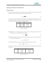
3.6 Free surface correction<br />
When tanks are partly lled in a loading condition, <strong>the</strong> free surface <strong>of</strong> <strong>the</strong> containing uid<br />
inuences <strong>the</strong> <strong>stability</strong> <strong>of</strong> <strong>the</strong> ship. The liquid's center <strong>of</strong> gravity moves when <strong>the</strong> ship heels.<br />
This leads to an apparent reduction <strong>of</strong> <strong>the</strong> GM. The corrected GM is usually determined by<br />
<strong>the</strong> formula 3.1 shown below<br />
GM corrected = GM solid − ∑ i<br />
ρ liquid i · I tank i<br />
△<br />
(3.1)<br />
for each partly lled tank i with <strong>the</strong> particular density <strong>of</strong> <strong>the</strong> liquid in tank ρ liquid , <strong>the</strong> particular<br />
moment <strong>of</strong> inertia <strong>of</strong> <strong>the</strong> free surface I tank <strong>and</strong> <strong>the</strong> displacement △ belonging to <strong>the</strong> particular<br />
loading condition .<br />
For <strong>the</strong> quasi-static <strong>intact</strong> <strong>stability</strong> analysis, this procedure is permissible. But for <strong>the</strong> highly<br />
nonlinear motions <strong>of</strong> a ship in seaways <strong>the</strong> correction is inaccurate, because <strong>the</strong> damping eect<br />
<strong>of</strong> <strong>the</strong> sloshing uid in <strong>the</strong> tank is not considered. For example this eect is used intentionally<br />
in roll damping tanks.<br />
For <strong>the</strong> <strong>seakeeping</strong> calculations it has been gured out, that both eects (roll damping due to<br />
sloshing <strong>and</strong> <strong>stability</strong> reduction due to <strong>the</strong> free surface) approximately compensate each o<strong>the</strong>r.<br />
Therefore <strong>the</strong> <strong>seakeeping</strong> calculations in E4 are always performed with an uncorrected GM solid .<br />
3.7 Intact <strong>stability</strong><br />
The <strong>intact</strong> <strong>stability</strong> is calculated according to <strong>the</strong> <strong>intact</strong> <strong>stability</strong> code <strong>of</strong> <strong>the</strong> IMO [4]. It is<br />
performed to determine <strong>the</strong> limiting <strong>intact</strong> <strong>stability</strong> criterion in <strong>the</strong> examined ballast arrival<br />
loading condition. The following six criteria are considered:<br />
1. The initial metacentric height GM 0 (including free surfaces) shall not be less than 0.15 m.<br />
(named in <strong>the</strong> following: Initial GM is 0.15 m)<br />
2. The righting lever GZ shall be at least 0.2 m at an angle <strong>of</strong> heel equal to or greater than<br />
30 ◦ . (named in <strong>the</strong> following: GZ is 0.2 at 30 ◦ )<br />
3. The maximum righting lever shall occur at an angle <strong>of</strong> heel not less than 25 ◦ . (named in<br />
<strong>the</strong> following: Max. GZ at 25 ◦ )<br />
4. The area under <strong>the</strong> GZ curve shall not be less than 0.055 metre − radians up to 30 ◦ angle<br />
<strong>of</strong> heel. (named in <strong>the</strong> following: Area (0, 30) = 0.055 m · rad)<br />
5. The area under <strong>the</strong> GZ curve shall not be less than0.09 metre − radians up to 40 ◦ angle<br />
<strong>of</strong> heel. (named in <strong>the</strong> following: Area (0, 40) = 0.090 m · rad)<br />
6. The area under <strong>the</strong> GZ curve between <strong>the</strong> angles <strong>of</strong> heel <strong>of</strong> 30 ◦ <strong>and</strong> 40 ◦ shall not be less<br />
than 0.03 metre − radians. (named in <strong>the</strong> following: Area (30, 40) = 0.030 m · rad)<br />
3.8 Cross-curves <strong>of</strong> <strong>stability</strong><br />
Fur<strong>the</strong>rmore <strong>the</strong> cross-curves <strong>of</strong> <strong>stability</strong> <strong>of</strong> <strong>the</strong> hull for xed <strong>and</strong> free trim are calculated. The<br />
resulting curves in E4 are compared to <strong>the</strong> curves derived from <strong>the</strong> <strong>stability</strong> booklet. The better<br />
<strong>the</strong> curves match, <strong>the</strong> better <strong>the</strong> E4 calculation model matches <strong>the</strong> calculating model <strong>of</strong> <strong>the</strong><br />
shipyard. Thereby its assured, that <strong>the</strong> result <strong>of</strong> <strong>the</strong> calculations are applicable to <strong>the</strong> realized<br />
vessel.<br />
15
3 Data input<br />
At this <strong>the</strong> cross-curves for small angles should have approximately equivalent values. For large<br />
angles (> 60 ◦ ), <strong>the</strong> values may dier. This is due to <strong>the</strong> not considered hatchway coamings in <strong>the</strong><br />
calculation models. In <strong>the</strong> scope <strong>of</strong> <strong>the</strong> subsequent analysis, this simplied model is considered<br />
to be applicable, because <strong>the</strong> vessels never reach higher rolling angles than ∼ 40 ◦ .<br />
3.9 Bilge keel dimensions<br />
During <strong>seakeeping</strong> calculation, <strong>the</strong> bilge keel dimensions have to be considered. They are needed<br />
to determine <strong>the</strong>ir eect on <strong>the</strong> ship's roll damping. Because <strong>the</strong> bilge keel area is not given for<br />
some ships, <strong>the</strong> value <strong>the</strong>n has to be estimated. Therefore a mean value is calculated out <strong>of</strong> <strong>the</strong><br />
given bilge keel dimensions with equation 3.2 as follows:<br />
mean value = 1 n<br />
n∑<br />
i=1<br />
L pp i<br />
A BK i<br />
∼ = 5.36 [ 1/m] (3.2)<br />
with <strong>the</strong> index for each ship i, <strong>the</strong> total number <strong>of</strong> ships with given bilge keel dimensions n, <strong>the</strong><br />
bilge keel area A BK <strong>and</strong> <strong>the</strong> length between perpendicular L pp <strong>of</strong> <strong>the</strong> respective ship. According<br />
to <strong>the</strong> mean value, <strong>the</strong> bilge keel area for ships without given value is estimated by:<br />
A BK i = L pp i [<br />
m<br />
2 ] (3.3)<br />
5.36<br />
Figure 3.3 shows <strong>the</strong> distribution <strong>of</strong> <strong>the</strong> respective bilge keel area against L pp . The numbers<br />
above <strong>the</strong> entries indicate <strong>the</strong> number <strong>of</strong> <strong>the</strong> examined vessel according to chapter 4.<br />
100,00<br />
90,00<br />
11<br />
Bilge keel area [m 2 ]<br />
80,00<br />
70,00<br />
60,00<br />
50,00<br />
40,00<br />
10<br />
estimated values<br />
13<br />
5<br />
6<br />
12<br />
7<br />
1<br />
3<br />
9<br />
4<br />
8<br />
2<br />
15<br />
14<br />
30,00<br />
190 200 210 220 230 240 250 260 270 280 290 300 310 320 330<br />
L PP [m]<br />
Actual values <strong>of</strong> examined vessels<br />
Mean value curve<br />
Figure 3.3: Bilge keel area distribution<br />
16
3.10 Bridge height<br />
3.10 Bridge height<br />
The severely <strong>and</strong> fatally injured crew members mentioned in <strong>the</strong> beginning, have been on duty<br />
on <strong>the</strong> vessel's bridge when <strong>the</strong> accident occurred. Hence <strong>the</strong> transversal accelerations aecting<br />
a human on <strong>the</strong> bridge are calculated in <strong>the</strong> fur<strong>the</strong>r scope <strong>of</strong> this <strong>the</strong>sis. The transversal accelerations<br />
in seaways are calculated at one meter above <strong>the</strong> bridge deck. This value is assumed for<br />
<strong>the</strong> vertical center <strong>of</strong> gravity <strong>of</strong> a human.<br />
For <strong>the</strong> roll behavior <strong>of</strong> a ship in seaway it can be estimated, that its roll axis is located in<br />
<strong>the</strong> proximity <strong>of</strong> <strong>the</strong> vessel's line <strong>of</strong> oatation according to Abdel-Maksoud [11]. This is why<br />
<strong>the</strong> transversal accelerations are inherently higher on <strong>the</strong> bridge than on lower decks. In this<br />
examination, <strong>the</strong> line <strong>of</strong> oatation is <strong>the</strong> ballast arrival loading condition waterline. The bridge<br />
height above <strong>the</strong> ballast arrival waterline <strong>of</strong> <strong>the</strong> 15 vessels against L P P is shown in gure 3.4.<br />
Actual values <strong>of</strong> examined vessels<br />
Height <strong>of</strong> bridge above ballast<br />
arrival waterline [m]<br />
42,0<br />
41,0<br />
40,0<br />
39,0<br />
38,0<br />
37,0<br />
36,0<br />
6<br />
8<br />
12<br />
35,0<br />
7<br />
34,0<br />
4<br />
33,0<br />
9<br />
32,0 13<br />
5<br />
31,0<br />
30,0<br />
200 210 220 230 240 250 260 270 280 290 300 310 320 330<br />
3<br />
1<br />
Lpp [m]<br />
Actual values <strong>of</strong> examined vessels<br />
2<br />
14<br />
15<br />
11<br />
Figure 3.4: Bridge height above ballast arrival waterline<br />
17
3 Data input<br />
3.11 Size range <strong>of</strong> <strong>the</strong> examined vessels<br />
The smallest examined vessel is nearly 200 m whereas <strong>the</strong> largest vessel is more than 320 m<br />
long. Figure 3.5 opposes <strong>the</strong> displacement to <strong>the</strong> length between perpendicular. To visualise <strong>the</strong><br />
dierences between <strong>the</strong> examined vessels, <strong>the</strong> lateral view <strong>of</strong> three <strong>of</strong> <strong>the</strong>m is given. The detailed<br />
ship data <strong>and</strong> main dimensions for each ship are given in <strong>the</strong> respective section <strong>of</strong> chapter 4.<br />
130000<br />
120000<br />
110000<br />
14<br />
15<br />
11<br />
100000<br />
Displacement at T design [t]<br />
90000<br />
80000<br />
70000<br />
60000<br />
50000<br />
5<br />
6<br />
12<br />
7<br />
1<br />
3<br />
9<br />
4<br />
8<br />
2<br />
40000<br />
10<br />
13<br />
30000<br />
190 200 210 220 230 240 250 260 270 280 290 300 310 320 330<br />
L PP [m]<br />
Figure 3.5: Vessels size range<br />
3.12 Sea conditions to be examined<br />
According to <strong>the</strong> accident sea conditions named in chapter 1.1, <strong>the</strong> following situations are examined.<br />
As mentioned in chapter 2.2, <strong>the</strong> seaway is described by a signicant wave period T S <strong>and</strong><br />
a signicant wave height H 1/3 . For each analysed vessel a speed v <strong>and</strong> a wave encountering angle<br />
is assumed according to <strong>the</strong> respective accident situation. The encountering angle is measured<br />
from astern, so 0 ◦ means <strong>the</strong> ship encounters a following sea.<br />
Table 3.1: Accident situations<br />
Accident Corresponds to <strong>the</strong><br />
Encount.<br />
v [kts]<br />
situation accident <strong>of</strong><br />
angle [ ◦ ]<br />
T S [s] H 1/3 [m]<br />
Situation 1 Chicago Express 3 150 9.5 7.5<br />
Situation 2 2468 TEU vessel 3 150 8.5 7.0<br />
Situation 3 2500 TEU vessel 5 130 9.5 7.0<br />
18
4 <strong>Examination</strong><br />
For each vessel <strong>the</strong> <strong>seakeeping</strong> behavior during <strong>the</strong> three accident situations is determined. This<br />
simulation extends to 20, 000 time steps, having a step size <strong>of</strong> 0.5 s each. This corresponds to a<br />
total duration <strong>of</strong> <strong>the</strong> simulation in real time <strong>of</strong> 10, 000 s.<br />
This chapter explains <strong>the</strong> data sets for all analysed vessels. The compilation contains a simplied<br />
lines plan including <strong>the</strong> lateral areas <strong>and</strong> a few main dimensions. A detailed list <strong>of</strong> all<br />
main dimensions <strong>and</strong> <strong>the</strong> data for <strong>the</strong> respective ballast arrival loading condition can be found<br />
in <strong>the</strong> appendix A. In addition, some specic characteristics <strong>of</strong> <strong>the</strong> ship are named. (e.g. <strong>the</strong><br />
quality <strong>of</strong> <strong>the</strong> calculation model or <strong>the</strong> hullform). At this <strong>the</strong> explanations concerning <strong>the</strong> ability<br />
<strong>of</strong> passing <strong>the</strong> Panama Canal, apply on <strong>the</strong> canal before its enlarging, which will be completed<br />
in <strong>the</strong> year 2014/2015. Fur<strong>the</strong>r with <strong>the</strong> referenced c B value for each vessel, <strong>the</strong> neness <strong>of</strong> <strong>the</strong><br />
hull forms is described <strong>and</strong> can be compared to o<strong>the</strong>r vessels.<br />
Fur<strong>the</strong>rmore <strong>the</strong> maximum rolling angles <strong>and</strong> maximum transversal accelerations on <strong>the</strong> bridge<br />
are given, resulting from each <strong>of</strong> <strong>the</strong> three above named accident situations. For <strong>the</strong> worst scenario<br />
<strong>the</strong> statistical distribution <strong>of</strong> <strong>the</strong> occurring accelerations is given by a histogram, where <strong>the</strong><br />
maximum transversal acceleration is derived from. The mean value <strong>of</strong> <strong>the</strong> normalized amplitudes<br />
<strong>and</strong> <strong>the</strong> associated st<strong>and</strong>ard deviation as well as <strong>the</strong> number <strong>of</strong> calculated periods in <strong>the</strong> simulation<br />
time <strong>of</strong> 10, 000 s are also shown in <strong>the</strong> histogram. It is to be noted, that <strong>the</strong> histograms<br />
do not have <strong>the</strong> same scale on <strong>the</strong>ir x-axis. So <strong>the</strong> histograms <strong>of</strong> two dierent vessels can not be<br />
compared directly. The order <strong>of</strong> <strong>the</strong> analysed vessels is r<strong>and</strong>omly chosen.<br />
4.1 Vessel No. 01<br />
Figure 4.1: Lines plan <strong>and</strong> lateral areas <strong>of</strong> Vessel No. 01<br />
Table 4.1: Main dimensions <strong>of</strong> Vessel No. 01<br />
Main dimensions Value Unit<br />
L pp 263.00 [m]<br />
B 40.00 [m]<br />
T D 12.00 [m]<br />
Containers 5,512 [TEU]<br />
The rst analysed vessel has <strong>the</strong> geometric capacity to carry 5, 512 T EU. Having <strong>the</strong> main<br />
dimensions according to table 4.1, this vessels must be classied as a smaller Post-Panamax<br />
19
4 <strong>Examination</strong><br />
vessels. The following characteristics <strong>of</strong> Vessel No. 01 are to be noted:<br />
ˆ The lines <strong>of</strong> <strong>the</strong> ship shown in gure 4.1 have a c B value <strong>of</strong> 0.57 on design draft.<br />
ˆ The documented bilge keel area is smaller than <strong>the</strong> mean value according to chapter 3.9.<br />
ˆ The <strong>stability</strong> in <strong>the</strong> ballast arrival loading condition is very high resulting in<br />
GM solid = 10.43 m.<br />
ˆ The limiting <strong>intact</strong> <strong>stability</strong> criterion (Max. GZ at 25 ◦ ) requires a GM min = 1.89 m.<br />
The calculated transversal accelerations on <strong>the</strong> bridge <strong>and</strong> <strong>the</strong> rolling angles for <strong>the</strong> three accident<br />
conditions are listed in table 4.2.<br />
Table 4.2: Results <strong>of</strong> <strong>the</strong> <strong>seakeeping</strong> calculation for Vessel No. 01<br />
Accident<br />
[<br />
a<br />
situation t max m/s<br />
2 ] ϕ max [ ◦ ]<br />
Situation 1 12.5 32<br />
Situation 2 12.5 29<br />
Situation 3 13.5 34<br />
The maximum acceleration occurs for accident situation 3. With a t max = 13.5 m /s 2 for accident<br />
situation 3 <strong>the</strong> examination already starts with a signicant value. The statistical distribution<br />
<strong>of</strong> <strong>the</strong> transversal accelerations in this situation is shown in gure 4.2.<br />
Figure 4.2: Transversal acceleration on <strong>the</strong> bridge <strong>of</strong> Vessel No. 01 in accident situation 3<br />
20
4.2 Vessel No. 02<br />
4.2 Vessel No. 02<br />
Figure 4.3: Lines plan <strong>and</strong> lateral areas <strong>of</strong> Vessel No. 02<br />
Table 4.3: Main dimensions <strong>of</strong> Vessel No. 02<br />
Main dimensions Value Unit<br />
L pp 292.00 [m]<br />
B 40.00 [m]<br />
T D 12.00 [m]<br />
Containers 6,500 [TEU]<br />
The second analysed vessel has <strong>the</strong> geometric capacity to carry 6, 500 T EU. Having <strong>the</strong> main<br />
dimensions according to table 4.3, it belongs to <strong>the</strong> medium sized Post-Panamax vessels. The<br />
following characteristics <strong>of</strong> Vessel No. 02 are to be noted:<br />
ˆ The lines <strong>of</strong> <strong>the</strong> ship shown in gure 4.3 have a c B value <strong>of</strong> 0.61 on design draft<br />
ˆ The documented bilge keel area is signicantly smaller than <strong>the</strong> mean value according to<br />
chapter 3.9.<br />
ˆ The <strong>stability</strong> in <strong>the</strong> ballast arrival loading condition is very high resulting in<br />
GM solid = 9.88 m.<br />
ˆ The limiting <strong>intact</strong> <strong>stability</strong> criterion (Max. GZ at 25 ◦ ) requires a GM min = 2.12 m.<br />
The calculated transversal accelerations on <strong>the</strong> bridge <strong>and</strong> <strong>the</strong> rolling angles for <strong>the</strong> three accident<br />
conditions are listed in table 4.4.<br />
Table 4.4: Results <strong>of</strong> <strong>the</strong> <strong>seakeeping</strong> calculation for Vessel No. 02<br />
Accident<br />
[<br />
a<br />
situation t max m/s<br />
2 ] ϕ max [ ◦ ]<br />
Situation 1 7.5 18<br />
Situation 2 7.0 15<br />
Situation 3 11.5 28<br />
The maximum acceleration occurs for accident situation 3. The accelerations for Vessel<br />
No. 02 in situation 1 <strong>and</strong> 2 are signicant smaller than for Vessel No. 01. The statistical<br />
distribution <strong>of</strong> <strong>the</strong> transversal accelerations in this situation is shown in gure 4.4.<br />
21
4 <strong>Examination</strong><br />
Figure 4.4: Transversal acceleration on <strong>the</strong> bridge <strong>of</strong> Vessel No. 02 in accident situation 3<br />
4.3 Vessel No. 03<br />
Figure 4.5: Lines plan <strong>and</strong> lateral areas <strong>of</strong> Vessel No. 03<br />
Table 4.5: Main dimensions <strong>of</strong> Vessel No. 03<br />
Main dimensions Value Unit<br />
L pp 263.00 [m]<br />
B 40.00 [m]<br />
T D 12.50 [m]<br />
Containers 5,762 [TEU]<br />
The third analysed vessel has <strong>the</strong> geometric capacity to carry 5, 726 T EU. Having <strong>the</strong> main<br />
dimensions according to table 4.5, it belongs to <strong>the</strong> smaller Post-Panamax vessels. It has exactly<br />
<strong>the</strong> same main dimensions <strong>and</strong> an equivalent ballast arrival loading condition as Vessel No. 01.<br />
In contrast Vessel No. 03 has a higher c B value <strong>and</strong> <strong>the</strong>refore is able to carry more TEU at a<br />
slower design speed than Vessel No. 01. The following characteristics <strong>of</strong> Vessel No. 03 are to<br />
be noted:<br />
ˆ The lines <strong>of</strong> <strong>the</strong> ship shown in gure 4.5 have a c B value <strong>of</strong> 0.58 in design draft.<br />
22
4.3 Vessel No. 03<br />
ˆ The documented bilge keel area is signicantly higher than <strong>the</strong> mean value according to<br />
chapter 3.9.<br />
ˆ The <strong>stability</strong> in ballast arrival loading condition is very high resulting in a<br />
GM solid = 10.12 m.<br />
ˆ The limiting <strong>intact</strong> <strong>stability</strong> criterion (Max. GZ at 25 ◦ ) requires a GM min = 2.63 m.<br />
The calculated transversal accelerations on <strong>the</strong> bridge <strong>and</strong> <strong>the</strong> rolling angles for <strong>the</strong> three accident<br />
conditions are listed in table 4.6.<br />
Table 4.6: Results <strong>of</strong> <strong>the</strong> <strong>seakeeping</strong> calculation for Vessel No. 03<br />
Accident<br />
[<br />
a<br />
situation t max m/s<br />
2 ] ϕ max [ ◦ ]<br />
Situation 1 10.5 26<br />
Situation 2 11.0 23<br />
Situation 3 11.0 30<br />
The maximum acceleration occurs for accident situation 3, but <strong>the</strong> accelerations are comparable<br />
for each accident situation.<br />
Even though Vessel No. 01 <strong>and</strong> Vessel No. 03 are very similar, <strong>the</strong> values are smaller for<br />
<strong>the</strong> Vessel No. 03. A possible reason for this dierence is <strong>the</strong> 60% larger bilge keel area <strong>of</strong><br />
Vessel No. 03 <strong>and</strong> <strong>the</strong>refore a higher roll damping, respectively. The accelerations in accident<br />
situation 2 <strong>and</strong> 3 are <strong>the</strong> same. Therefore <strong>the</strong> situation <strong>of</strong> both with <strong>the</strong> higher rolling angle is<br />
stated to be <strong>the</strong> worst situation. The statistical distribution <strong>of</strong> <strong>the</strong> transversal accelerations in<br />
this situation is shown in gure 4.6.<br />
Figure 4.6: Transversal acceleration on <strong>the</strong> bridge <strong>of</strong> Vessel No. 03 in accident situation 3<br />
23
4 <strong>Examination</strong><br />
4.4 Vessel No. 04<br />
Figure 4.7: Lines plan <strong>and</strong> lateral areas <strong>of</strong> Vessel No. 04<br />
Table 4.7: Main dimensions <strong>of</strong> Vessel No. 04<br />
Main dimensions Value Unit<br />
L pp 280.75 [m]<br />
B 32.26 [m]<br />
T D 11.00 [m]<br />
Containers 4,402 [TEU]<br />
Vessel No. 04 has <strong>the</strong> geometric capacity to carry 4, 402 T EU. Having <strong>the</strong> main dimensions<br />
according to table 4.7, it complies with <strong>the</strong> maximum possible main dimensions to pass through<br />
<strong>the</strong> Panama Canal. The vessel is <strong>the</strong> rst typical Panamax container vessel, analysed within<br />
this examination. The following characteristics <strong>of</strong> Vessel No. 04 are to be noted:<br />
ˆ The lines <strong>of</strong> <strong>the</strong> ship shown in gure 4.7 have a c B value <strong>of</strong> 0.69 on design draft.<br />
ˆ The bilge keel area is not documented for this vessel <strong>and</strong> is estimated according to chapter<br />
3.9.<br />
ˆ The <strong>stability</strong> in ballast arrival loading condition is less high resulting in a GM solid = 6.39 m.<br />
ˆ The limiting <strong>intact</strong> <strong>stability</strong> criterion (Area (30, 40) = 0.030 m · rad) requires a<br />
GM min = 0.16 m.<br />
In general typical Panamax vessels with its large L /B ratio tend to small <strong>intact</strong> <strong>stability</strong> values.<br />
For Vessel No. 04 this leads to a very small GM min in ballast arrival loading condition. The c B<br />
value <strong>of</strong> 0.69 is <strong>the</strong> highest value <strong>of</strong> <strong>the</strong> analysed vessels. The calculated transversal accelerations<br />
on <strong>the</strong> bridge <strong>and</strong> <strong>the</strong> rolling angles for <strong>the</strong> three accident conditions are listed in table 4.8.<br />
Table 4.8: Results <strong>of</strong> <strong>the</strong> <strong>seakeeping</strong> calculation for Vessel No. 04<br />
Accident<br />
[<br />
a<br />
situation t max m/s<br />
2 ] ϕ max [ ◦ ]<br />
Situation 1 9.0 21<br />
Situation 2 8.0 18<br />
Situation 3 12.0 31<br />
The maximum acceleration occurs for accident situation 3. As already for Vessel No. 02, <strong>the</strong><br />
occurring transversal accelerations for accident situation 1 <strong>and</strong> 2 are signicant smaller than for<br />
24
4.5 Vessel No. 05<br />
accident situation 3. The statistical distribution <strong>of</strong> <strong>the</strong> transversal accelerations in this situation<br />
is shown in gure 4.8.<br />
Figure 4.8: Transversal acceleration on <strong>the</strong> bridge <strong>of</strong> Vessel No. 04 in accident situation 3<br />
4.5 Vessel No. 05<br />
Figure 4.9: Lines plan <strong>and</strong> lateral areas <strong>of</strong> Vessel No. 05<br />
Table 4.9: Main dimensions <strong>of</strong> Vessel No. 05<br />
Main dimensions Value Unit<br />
L pp 221.00 [m]<br />
B 32.20 [m]<br />
T D 11.82 [m]<br />
Containers 3,323 [TEU]<br />
The 5th examined vessel has <strong>the</strong> geometric capacity to carry 3, 323 T EU. Having <strong>the</strong> main<br />
dimensions according to table 4.9, it is also able to pass <strong>the</strong> Panama Canal, but it is shorter<br />
than Vessel No. 04. The following characteristics <strong>of</strong> Vessel No. 05 are to be noted:<br />
ˆ The lines <strong>of</strong> <strong>the</strong> ship shown in gure 4.9 have a c B value <strong>of</strong> 0.63 on design draft.<br />
25
4 <strong>Examination</strong><br />
ˆ The documented bilge keel area matches <strong>the</strong> mean value according to chapter 3.9.<br />
ˆ The <strong>stability</strong> in ballast arrival loading condition is moderately high resulting in a<br />
GM solid = 7.09 m.<br />
ˆ The limiting <strong>intact</strong> <strong>stability</strong> criterion (Area (30, 40) = 0.030 m · rad) requires a<br />
GM min = 0.53 m.<br />
The calculated transversal accelerations on <strong>the</strong> bridge <strong>and</strong> <strong>the</strong> rolling angles for <strong>the</strong> three accident<br />
conditions are listed in table 4.10.<br />
Table 4.10: Results <strong>of</strong> <strong>the</strong> <strong>seakeeping</strong> calculation for Vessel No. 05<br />
Accident<br />
[<br />
a<br />
situation t max m/s<br />
2 ] ϕ max [ ◦ ]<br />
Situation 1 12.0 32<br />
Situation 2 13.0 36<br />
Situation 3 13.0 35<br />
For <strong>the</strong> seaways <strong>of</strong> accident situation 2 <strong>and</strong> 3, <strong>the</strong> same maximum transversal accelerations on<br />
<strong>the</strong> bridge occur while <strong>the</strong> accelerations in accident situation 1 are also nearly as high. Because<br />
<strong>the</strong> rolling angle <strong>of</strong> situation 2 is <strong>the</strong> highest, this situation is stated to be <strong>the</strong> most critical. The<br />
statistical distribution <strong>of</strong> <strong>the</strong> transversal accelerations in this situation is shown in gure 4.10.<br />
Figure 4.10: Transversal acceleration on <strong>the</strong> bridge <strong>of</strong> Vessel No. 05 in accident situation 2<br />
26
4.6 Vessel No. 06<br />
4.6 Vessel No. 06<br />
Figure 4.11: Lines plan <strong>and</strong> lateral areas <strong>of</strong> Vessel No. 06<br />
Table 4.11: Main dimensions <strong>of</strong> Vessel No. 06<br />
Main dimensions Value Unit<br />
L pp 244.51 [m]<br />
B 32.25 [m]<br />
T D 10.00 [m]<br />
Containers 4,253 [TEU]<br />
Vessel No. 06 has <strong>the</strong> geometric capacity to carry 4, 253 T EU . Having <strong>the</strong> main dimensions<br />
according to table 4.11, it is ano<strong>the</strong>r midsized container vessel which may travel through <strong>the</strong><br />
Panama Canal. The following characteristics <strong>of</strong> Vessel No. 06 are to be noted:<br />
ˆ The lines <strong>of</strong> <strong>the</strong> ship shown in gure 4.11 have a c B value <strong>of</strong> 0.61 on design draft.<br />
ˆ The bilge keel area is not documented for this vessel <strong>and</strong> is estimated according to chapter<br />
3.9.<br />
ˆ The <strong>stability</strong> in ballast arrival loading condition is moderately high resulting in a<br />
GM solid = 7.47 m.<br />
ˆ The limiting <strong>intact</strong> <strong>stability</strong> criterion (Max. GZ at 25 ◦ ) requires a GM min = 1.33 m.<br />
The calculated transversal accelerations on <strong>the</strong> bridge <strong>and</strong> <strong>the</strong> rolling angles for <strong>the</strong> three accident<br />
conditions are listed in table 4.12.<br />
Table 4.12: Results <strong>of</strong> <strong>the</strong> <strong>seakeeping</strong> calculation for Vessel No. 06<br />
Accident<br />
[<br />
a<br />
situation t max m/s<br />
2 ] ϕ max [ ◦ ]<br />
Situation 1 9.0 23<br />
Situation 2 11.0 25<br />
Situation 3 12.0 29<br />
The maximum acceleration occurs for accident situation 3. The statistical distribution <strong>of</strong> <strong>the</strong><br />
transversal accelerations in this situation is shown in gure 4.12.<br />
27
4 <strong>Examination</strong><br />
Figure 4.12: Transversal acceleration on <strong>the</strong> bridge <strong>of</strong> Vessel No. 06 in accident situation 3<br />
4.7 Vessel No. 07<br />
Figure 4.13: Lines plan <strong>and</strong> lateral areas <strong>of</strong> Vessel No. 07<br />
Table 4.13: Main dimensions <strong>of</strong> Vessel No. 07<br />
Main dimensions Value Unit<br />
L pp 256.20 [m]<br />
B 32.20 [m]<br />
T D 10.00 [m]<br />
Containers 4,252 [TEU]<br />
Vessel No. 07 has <strong>the</strong> geometric capacity to carry 4, 252 T EU . Having <strong>the</strong> main dimensions<br />
according to table 4.13, <strong>the</strong> vessel is also a midsized, Panama canal capable container ship<br />
very similar to Vessel No. 06. The following characteristics <strong>of</strong> Vessel No. 07 are to be noted:<br />
ˆ The lines <strong>of</strong> <strong>the</strong> ship shown in gure 4.13 have a c B value <strong>of</strong> 0.62 on design draft.<br />
ˆ The documented bilge keel area is slightly smaller than <strong>the</strong> mean value according to chapter<br />
3.9.<br />
28
4.7 Vessel No. 07<br />
ˆ The <strong>stability</strong> in ballast arrival loading condition is moderately high resulting in a<br />
GM solid = 7.00 m.<br />
ˆ The limiting <strong>intact</strong> <strong>stability</strong> criterion (Max. GZ at 25 ◦ ) requires a GM min = 0.90 m.<br />
Compared to Vessel No. 06, <strong>the</strong> c B value <strong>of</strong> Vessel No. 07 is slightly larger <strong>and</strong> <strong>the</strong> GM min<br />
is slightly smaller. The calculated transversal accelerations on <strong>the</strong> bridge <strong>and</strong> <strong>the</strong> rolling angles<br />
for <strong>the</strong> three accident conditions are listed in table 4.14.<br />
Table 4.14: Results <strong>of</strong> <strong>the</strong> <strong>seakeeping</strong> calculation for Vessel No. 07<br />
Accident<br />
[<br />
a<br />
situation t max m/s<br />
2 ] ϕ max [ ◦ ]<br />
Situation 1 10.0 29<br />
Situation 2 10.0 24<br />
Situation 3 12.0 33<br />
As for Vessel No. 06 <strong>the</strong> maximum acceleration occurs for accident situation 3. The accelerations<br />
in situation 1 <strong>and</strong> 2 are also in <strong>the</strong> same scope for both vessels. Fur<strong>the</strong>rmore <strong>the</strong> dierences<br />
between <strong>the</strong> accelerations within <strong>the</strong>ir respective accident situations are not as high as for e.g.<br />
Vessel No. 02 or Vessel No. 04. The statistical distribution <strong>of</strong> <strong>the</strong> transversal accelerations<br />
in this situation is shown in gure 4.14.<br />
Figure 4.14: Transversal acceleration on <strong>the</strong> bridge <strong>of</strong> Vessel No. 07 in accident situation 3<br />
29
4 <strong>Examination</strong><br />
4.8 Vessel No. 08<br />
Figure 4.15: Lines plan <strong>and</strong> lateral areas <strong>of</strong> Vessel No. 08<br />
Table 4.15: Main dimensions <strong>of</strong> Vessel No. 08<br />
Main dimensions Value Unit<br />
L pp 283.20 [m]<br />
B 32.20 [m]<br />
T D 11.00 [m]<br />
Containers 5,041 [TEU]<br />
Vessel No. 08 has <strong>the</strong> geometric capacity to carry 5, 041 T EU. Having <strong>the</strong> main dimensions<br />
according to table 4.15, it is a typical Panamax container vessel like Vessel No. 04. The<br />
following characteristics <strong>of</strong> Vessel No. 08 are to be noted:<br />
ˆ The lines <strong>of</strong> <strong>the</strong> ship shown in gure 4.15 have a c B value <strong>of</strong> 0.65 on design draft.<br />
ˆ The documented bilge keel area is slightly larger than <strong>the</strong> mean value according to chapter<br />
3.9.<br />
ˆ The <strong>stability</strong> in ballast arrival loading condition is less high resulting in a GM solid = 6.23 m.<br />
ˆ The limiting <strong>intact</strong> <strong>stability</strong> criterion (Area (30, 40) = 0.030 m · rad) requires a<br />
GM min = 0.40 m.<br />
As for Vessel No. 04, <strong>the</strong> rst analysed Panamax vessel, <strong>the</strong> c B value is relatively high for a<br />
container vessel <strong>and</strong> <strong>the</strong> GM min is small. The calculated transversal accelerations on <strong>the</strong> bridge<br />
<strong>and</strong> <strong>the</strong> rolling angles for <strong>the</strong> three accident conditions are listed in table 4.16.<br />
Table 4.16: Results <strong>of</strong> <strong>the</strong> <strong>seakeeping</strong> calculation for Vessel No. 08<br />
Accident<br />
[<br />
a<br />
situation t max m/s<br />
2 ] ϕ max [ ◦ ]<br />
Situation 1 11.0 27<br />
Situation 2 9.0 18<br />
Situation 3 13.0 35<br />
The maximum acceleration occurs for accident situation 3. The distribution <strong>of</strong> <strong>the</strong> highest<br />
accelerations on <strong>the</strong> three accident situations is similar to <strong>the</strong> distribution <strong>of</strong> Vessel No. 04,<br />
where <strong>the</strong> highest value also occurs for accident situation 3 while <strong>the</strong> lowest value occurs for<br />
situation 2. The statistical distribution <strong>of</strong> <strong>the</strong> transversal accelerations in this situation is shown<br />
in gure 4.16.<br />
30
4.9 Vessel No. 09<br />
Figure 4.16: Transversal acceleration on <strong>the</strong> bridge <strong>of</strong> Vessel No. 08 in accident situation 3<br />
4.9 Vessel No. 09<br />
Figure 4.17: Lines plan <strong>and</strong> lateral areas <strong>of</strong> Vessel No. 09<br />
Table 4.17: Main dimensions <strong>of</strong> Vessel No. 09<br />
Main dimensions Value Unit<br />
L pp 277.00 [m]<br />
B 32.25 [m]<br />
T D 12.20 [m]<br />
Containers 4,318 [TEU]<br />
Vessel No. 09 has <strong>the</strong> geometric capacity to carry 4, 318 T EU. Having <strong>the</strong> main dimensions<br />
according to table 4.17, it is a typical Panamax container vessel like Vessel No. 04 <strong>and</strong> Vessel<br />
No. 08. Due to its design draft <strong>of</strong> 12.2 m, <strong>the</strong> vessel is not able to pass <strong>the</strong> Panama Canal in<br />
design loading condition, because in <strong>the</strong> canal <strong>the</strong> draft is limited to 12.04 m. Ano<strong>the</strong>r loading<br />
condition with a smaller draft has to be chosen for <strong>the</strong> passage. The following characteristics <strong>of</strong><br />
Vessel No. 09 are to be noted:<br />
ˆ The lines <strong>of</strong> <strong>the</strong> ship shown in gure 4.17 have a c B value <strong>of</strong> 0.65 on design draft. Fur<strong>the</strong>rmore<br />
<strong>the</strong> slanted transom is unusual.<br />
31
4 <strong>Examination</strong><br />
ˆ The documented bilge keel area is slightly smaller than <strong>the</strong> mean value according to chapter<br />
3.9.<br />
ˆ The <strong>stability</strong> in ballast arrival loading condition is less high resulting in <strong>the</strong> smallest GM<br />
<strong>of</strong> <strong>the</strong> examination GM solid = 5.09 m.<br />
ˆ The limiting <strong>intact</strong> <strong>stability</strong> criterion (Area (0, 40) = 0.090 m · rad) requires a<br />
GM min = 0.32 m.<br />
Like <strong>the</strong> o<strong>the</strong>r Panamax vessels, also Vessel No. 09 has a relatively high c B value <strong>and</strong> a very<br />
small GM min . The calculated transversal accelerations on <strong>the</strong> bridge <strong>and</strong> <strong>the</strong> rolling angles for<br />
<strong>the</strong> three accident conditions are listed in table 4.18.<br />
Table 4.18: Results <strong>of</strong> <strong>the</strong> <strong>seakeeping</strong> calculation for Vessel No. 09<br />
Accident<br />
[<br />
a<br />
situation t max m/s<br />
2 ] ϕ max [ ◦ ]<br />
Situation 1 12.0 38<br />
Situation 2 7.5 22<br />
Situation 3 14.0 35<br />
Until now <strong>the</strong> maximum transversal acceleration <strong>of</strong> 14 m /s 2 in situation 3 is <strong>the</strong> worst value<br />
calculated. As for Vessel No. 04 <strong>and</strong> Vessel No. 08, <strong>the</strong> highest acceleration value occurs for<br />
situation 3, while <strong>the</strong> lowest is associated to situation 2. Notable is <strong>the</strong> fact, that <strong>the</strong> highest<br />
value is twice as high as <strong>the</strong> lowest. The statistical distribution <strong>of</strong> <strong>the</strong> transversal accelerations<br />
in this situation is shown in gure 4.18.<br />
Figure 4.18: Transversal acceleration on <strong>the</strong> bridge <strong>of</strong> Vessel No. 09 in accident situation 3<br />
32
4.10 Vessel No. 10<br />
4.10 Vessel No. 10<br />
Figure 4.19: Lines plan <strong>and</strong> lateral areas <strong>of</strong> Vessel No. 10<br />
Table 4.19: Main dimensions <strong>of</strong> Vessel No. 10<br />
Main dimensions Value Unit<br />
L pp 195.40 [m]<br />
B 29.80 [m]<br />
T D 10.10 [m]<br />
Containers 2,478 [TEU]<br />
Vessel No. 10 has <strong>the</strong> geometric capacity to carry 2, 478 T EU. Having <strong>the</strong> main dimensions<br />
according to table 4.19, it is <strong>the</strong> smallest analysed vessel. In addition it is <strong>the</strong> only vessel equipped<br />
with cranes <strong>and</strong> a deck house located at <strong>the</strong> ship's aft end. The following characteristics <strong>of</strong><br />
Vessel No. 10 are to be noted:<br />
ˆ The lines <strong>of</strong> <strong>the</strong> ship shown in gure 4.19 have a c B value <strong>of</strong> 0.63 on design draft.<br />
ˆ The bilge keel area is not documented for this vessel <strong>and</strong> is estimated according to chapter<br />
3.9.<br />
ˆ The <strong>stability</strong> in ballast arrival loading condition is less high resulting in a GM solid = 5.95 m.<br />
ˆ The limiting <strong>intact</strong> <strong>stability</strong> criterion (Area (0, 40) = 0.090 m · rad) requires a<br />
GM min = 0.38 m.<br />
The calculated transversal accelerations on <strong>the</strong> bridge <strong>and</strong> <strong>the</strong> rolling angles for <strong>the</strong> three accident<br />
conditions are listed in table 4.20.<br />
Table 4.20: Results <strong>of</strong> <strong>the</strong> <strong>seakeeping</strong> calculation for Vessel No. 10<br />
Accident<br />
[<br />
a<br />
situation t max m/s<br />
2 ] ϕ max [ ◦ ]<br />
Situation 1 12.0 32<br />
Situation 2 14.5 43<br />
Situation 3 12.0 36<br />
The maximum acceleration <strong>of</strong> 14.5 m /s 2 occurs for accident situation 2 while <strong>the</strong> associated<br />
rolling angle <strong>of</strong> 43 ◦ is <strong>the</strong> highest calculated value in <strong>the</strong> whole examination. The statistical<br />
distribution <strong>of</strong> <strong>the</strong> transversal accelerations in this situation is shown in gure 4.20.<br />
33
4 <strong>Examination</strong><br />
Figure 4.20: Transversal acceleration on <strong>the</strong> bridge <strong>of</strong> Vessel No. 10 in accident situation 2<br />
4.11 Vessel No. 11<br />
Figure 4.21: Lines plan <strong>and</strong> lateral areas <strong>of</strong> Vessel No. 11<br />
Table 4.21: Main dimensions <strong>of</strong> Vessel No. 11<br />
Main dimensions Value Unit<br />
L pp 322.60 [m]<br />
B 45.60 [m]<br />
T D 13.00 [m]<br />
Containers 8,600 [TEU]<br />
Vessel No. 11 has <strong>the</strong> geometric capacity to carry 8, 600 T EU. Having <strong>the</strong> main dimensions<br />
according to table 4.21, it is <strong>the</strong> largest vessel analysed. It belongs to <strong>the</strong> class <strong>of</strong> large Post-<br />
Panamax vessels. The following characteristics <strong>of</strong> Vessel No. 11 are to be noted:<br />
ˆ The lines <strong>of</strong> <strong>the</strong> ship shown in gure 4.21 have a c B value <strong>of</strong> 0.59 on design draft.<br />
ˆ The documented bilge keel area is much larger than <strong>the</strong> mean value according to chapter<br />
3.9.<br />
ˆ The <strong>stability</strong> in ballast arrival loading condition is extremely high resulting in a<br />
GM solid = 12.96 m.<br />
34
4.11 Vessel No. 11<br />
ˆ The limiting <strong>intact</strong> <strong>stability</strong> criterion (Max. GZ at 25 ◦ ) requires a GM min = 4.20 m.<br />
The ship is very ne with its c B value <strong>of</strong> 0.59. The <strong>stability</strong> values GM solid <strong>and</strong> mainly GM min<br />
have a signicant higher order <strong>of</strong> magnitude, than <strong>the</strong> values <strong>of</strong> <strong>the</strong> previous analysed vessels.<br />
The calculated transversal accelerations on <strong>the</strong> bridge <strong>and</strong> <strong>the</strong> rolling angles for <strong>the</strong> three accident<br />
conditions are listed in table 4.22.<br />
Table 4.22: Results <strong>of</strong> <strong>the</strong> <strong>seakeeping</strong> calculation for Vessel No. 11<br />
Accident<br />
[<br />
a<br />
situation t max m/s<br />
2 ] ϕ max [ ◦ ]<br />
Situation 1 4.0 11<br />
Situation 2 3.5 8<br />
Situation 3 5.5 12<br />
The maximum acceleration occurs for accident situation 3. But <strong>the</strong> calculated accelerations are<br />
considerably smaller than for <strong>the</strong> previous analysed vessels. The statistical distribution<br />
<strong>of</strong> <strong>the</strong> transversal accelerations in this situation is shown in gure 4.22.<br />
Figure 4.22: Transversal acceleration on <strong>the</strong> bridge <strong>of</strong> Vessel No. 11 in accident situation 3<br />
35
4 <strong>Examination</strong><br />
4.12 Vessel No. 12<br />
Figure 4.23: Lines plan <strong>and</strong> lateral areas <strong>of</strong> Vessel No. 12<br />
Table 4.23: Main dimensions <strong>of</strong> Vessel No. 12<br />
Main dimensions Value Unit<br />
L pp 249.03 [m]<br />
B 32.20 [m]<br />
T D 11.30 [m]<br />
Containers 4,300 [TEU]<br />
Vessel No. 12 has <strong>the</strong> geometric capacity to carry 4, 300 T EU. Having <strong>the</strong> main dimensions<br />
according to table 4.23, it is ano<strong>the</strong>r midsized container vessel which may travel through <strong>the</strong><br />
Panama Canal. The vessel is comparable to Vessel No. 07, which has nearly <strong>the</strong> same<br />
dimensions, a slightly smaller c B value <strong>and</strong> <strong>the</strong>refore a ner hullform as well as a smaller geometric<br />
TEU capacity. The following characteristics <strong>of</strong> Vessel No. 12 are to be noted:<br />
ˆ The lines <strong>of</strong> <strong>the</strong> ship shown in gure 4.23 have a c B value <strong>of</strong> 0.65 on design draft.<br />
ˆ The documented bilge keel area is signicant smaller than <strong>the</strong> mean value according to<br />
chapter 3.9.<br />
ˆ The <strong>stability</strong> in ballast arrival loading condition is moderately high resulting in a<br />
GM solid = 7.18 m.<br />
ˆ The limiting <strong>intact</strong> <strong>stability</strong> criterion (Max. GZ at 25 ◦ ) requires a GM min = 1.28 m.<br />
The calculated transversal accelerations on <strong>the</strong> bridge <strong>and</strong> <strong>the</strong> rolling angles for <strong>the</strong> three accident<br />
conditions are listed in table 4.24.<br />
Table 4.24: Results <strong>of</strong> <strong>the</strong> <strong>seakeeping</strong> calculation for Vessel No. 12<br />
Accident<br />
[<br />
a<br />
situation t max m/s<br />
2 ] ϕ max [ ◦ ]<br />
Situation 1 10.5 25<br />
Situation 2 11.0 26<br />
Situation 3 14.0 35<br />
The maximum acceleration occurs for accident situation 3. The maximum acceleration is<br />
higher, than for <strong>the</strong> comparable Vessel No. 07. The statistical distribution <strong>of</strong> <strong>the</strong> transversal<br />
accelerations in this situation is shown in gure 4.24.<br />
36
4.13 Vessel No. 13<br />
Figure 4.24: Transversal acceleration on <strong>the</strong> bridge <strong>of</strong> Vessel No. 12 in accident situation 3<br />
4.13 Vessel No. 13<br />
Figure 4.25: Lines plan <strong>and</strong> lateral areas <strong>of</strong> Vessel No. 13<br />
Table 4.25: Main dimensions <strong>of</strong> Vessel No. 13<br />
Main dimensions Value Unit<br />
L pp 210.25 [m]<br />
B 30.00 [m]<br />
T D 10.10 [m]<br />
Containers 2,824 [TEU]<br />
Vessel No. 13 has <strong>the</strong> geometric capacity to carry 2, 824 T EU. Having <strong>the</strong> main dimensions<br />
according to table 4.25, it is <strong>the</strong> second smallest analysed vessel. The following characteristics<br />
<strong>of</strong> Vessel No. 13 are to be noted:<br />
ˆ The lines <strong>of</strong> <strong>the</strong> ship shown in gure 4.25 have a c B value <strong>of</strong> 0.62 on design draft.<br />
ˆ The documented bilge keel area matches <strong>the</strong> mean value according to chapter 3.9.<br />
ˆ The <strong>stability</strong> in ballast arrival loading condition is moderately high resulting in a<br />
GM solid = 6.98 m.<br />
37
4 <strong>Examination</strong><br />
ˆ The limiting <strong>intact</strong> <strong>stability</strong> criterion (Area (30, 40) = 0.030 m · rad) requires a<br />
GM min = 0.65 m.<br />
The calculated transversal accelerations on <strong>the</strong> bridge <strong>and</strong> <strong>the</strong> rolling angles for <strong>the</strong> three accident<br />
conditions are listed in table 4.26.<br />
Table 4.26: Results <strong>of</strong> <strong>the</strong> <strong>seakeeping</strong> calculation for Vessel No. 13<br />
Accident<br />
[<br />
a<br />
situation t max m/s<br />
2 ] ϕ max [ ◦ ]<br />
Situation 1 12.0 31<br />
Situation 2 15.0 36<br />
Situation 3 12.5 32<br />
The maximum acceleration occurs for accident situation 2. The transversal acceleration <strong>of</strong><br />
15 m /s 2 in accident situation 2 is <strong>the</strong> highest value that occurs in <strong>the</strong> scope <strong>of</strong> <strong>the</strong> simulations.<br />
Mentionable is <strong>the</strong> fact, that all smaller vessels analysed in this chapter, are critical in accident<br />
situation 2, while for <strong>the</strong> o<strong>the</strong>r vessels <strong>the</strong> critical situation is situation 3. Apparently <strong>the</strong> seaway<br />
in situation 2 with a shorter signicant wave period <strong>of</strong> T S = 8.5 s stronger excites <strong>the</strong> small<br />
vessels. The statistical distribution <strong>of</strong> <strong>the</strong> transversal accelerations in this situation is shown in<br />
gure 4.26.<br />
Figure 4.26: Transversal acceleration on <strong>the</strong> bridge <strong>of</strong> Vessel No. 13 in accident situation 2<br />
38
4.14 Vessel No. 14<br />
4.14 Vessel No. 14<br />
Figure 4.27: Lines plan <strong>and</strong> lateral areas <strong>of</strong> Vessel No. 14<br />
Table 4.27: Main dimensions <strong>of</strong> Vessel No. 14<br />
Main dimensions Value Unit<br />
L pp 319.00 [m]<br />
B 42.80 [m]<br />
T D 13.00 [m]<br />
Containers 8,600 [TEU]<br />
Vessel No. 14 has <strong>the</strong> geometric capacity to carry 8, 600 T EU. Having <strong>the</strong> main dimensions<br />
according to table 4.27, it belongs to <strong>the</strong> class <strong>of</strong> <strong>the</strong> large Post-Panamax vessels. With Vessel<br />
No. 14 <strong>the</strong> Chicago Express takes part <strong>of</strong> <strong>the</strong> analysis, which is <strong>the</strong> vessel involved in accident<br />
situation 1. For <strong>the</strong> BSU accident report [1] it has already been examined, although referring to<br />
a dierent loading condition. The following characteristics <strong>of</strong> <strong>the</strong> Chicago Express are to be<br />
noted:<br />
ˆ The lines <strong>of</strong> <strong>the</strong> ship shown in gure 4.27 have a c B value <strong>of</strong> 0.66 on design draft.<br />
ˆ The documented bilge keel area is a little bit larger than <strong>the</strong> mean value according to<br />
chapter 3.9.<br />
ˆ The <strong>stability</strong> in ballast arrival loading condition is extremely high resulting in a<br />
GM solid = 12.40 m.<br />
ˆ The limiting <strong>intact</strong> <strong>stability</strong> criterion (Max. GZ at 25 ◦ ) requires a GM min = 4.92 m.<br />
Besides Vessel No. 11, <strong>the</strong> Chicago Express is <strong>the</strong> second vessel in <strong>the</strong> examination out<br />
<strong>of</strong> <strong>the</strong> class <strong>of</strong> large Post-Panamax vessels. With a c B value <strong>of</strong> 0.66, <strong>the</strong> Chicago Express<br />
has not such a ne shaped hull as Vessel No. 11. But <strong>the</strong> <strong>stability</strong> values GM solid <strong>and</strong> most<br />
notably GM min also have a signicant higher order <strong>of</strong> magnitude, than <strong>the</strong> values for <strong>the</strong> smaller<br />
analysed vessels. The calculated transversal accelerations on <strong>the</strong> bridge <strong>and</strong> <strong>the</strong> rolling angles<br />
for <strong>the</strong> three accident conditions are listed in table 4.28.<br />
Table 4.28: Results <strong>of</strong> <strong>the</strong> <strong>seakeeping</strong> calculation for Vessel No. 14<br />
Accident<br />
[<br />
a<br />
situation t max m/s<br />
2 ] ϕ max [ ◦ ]<br />
Situation 1 3.0 7<br />
Situation 2 3.5 8<br />
Situation 3 3.0 8<br />
39
4 <strong>Examination</strong><br />
The maximum acceleration occurs for accident situation 2. As for <strong>the</strong> rst large vessel analyse,<br />
Vessel No. 11, <strong>the</strong> calculated accelerations are considerably smaller than for <strong>the</strong> previous<br />
analysed vessels. Never<strong>the</strong>less in <strong>the</strong> accident condition <strong>of</strong> Vessel No. 11, <strong>the</strong> Chicago Express,<br />
<strong>the</strong> transversal accelerations on <strong>the</strong> bridge exceeded 1.0 g (refer to BSU investigation report [1])!<br />
The statistical distribution <strong>of</strong> <strong>the</strong> transversal accelerations in this situation is shown in gure<br />
4.28.<br />
Figure 4.28: Transversal acceleration on <strong>the</strong> bridge <strong>of</strong> Vessel No. 14 in accident situation 2<br />
40
4.15 Vessel No. 15<br />
4.15 Vessel No. 15<br />
Figure 4.29: Lines plan <strong>and</strong> lateral areas <strong>of</strong> Vessel No. 15<br />
Table 4.29: Main dimensions <strong>of</strong> Vessel No. 15<br />
Main dimensions Value Unit<br />
L pp 319.00 [m]<br />
B 42.80 [m]<br />
T D 13.00 [m]<br />
Containers 8,200 [TEU]<br />
The last analysed vessel has <strong>the</strong> geometric capacity to carry 8, 200 T EU. Having <strong>the</strong> main<br />
dimensions according to table 4.29, it belongs to <strong>the</strong> large Post-Panamax vessels. The vessel is<br />
very similar to <strong>the</strong> Chicago Express as it has exactly <strong>the</strong> same main dimensions as well as an<br />
equivalent ballast arrival loading condition. The following characteristics <strong>of</strong> Vessel No. 15 are<br />
to be noted:<br />
ˆ The lines <strong>of</strong> <strong>the</strong> ship shown in gure 4.29 have a c B value <strong>of</strong> 0.65 on design draft<br />
ˆ The documented bilge keel area is larger than <strong>the</strong> mean value according to chapter 3.9<br />
ˆ The calculated cross-curves in E4 coincide well with <strong>the</strong> ones stated in <strong>the</strong> trim & <strong>stability</strong><br />
booklet<br />
ˆ The <strong>stability</strong> in ballast arrival loading condition is extremely high resulting in a<br />
GM solid = 12.49 m<br />
ˆ The limiting <strong>intact</strong> <strong>stability</strong> criterion (Max. GZ at 25 ◦ ) requires a GM min = 4.77 m<br />
The calculated transversal accelerations on <strong>the</strong> bridge <strong>and</strong> <strong>the</strong> rolling angles for <strong>the</strong> three accident<br />
conditions are listed in table 4.30.<br />
Table 4.30: Results <strong>of</strong> <strong>the</strong> <strong>seakeeping</strong> calculation for Vessel No. 15<br />
Accident<br />
[<br />
a<br />
situation t max m/s<br />
2 ] ϕ max [ ◦ ]<br />
Situation 1 4.5 11<br />
Situation 2 4.0 8<br />
Situation 3 5.0 11<br />
The maximum acceleration occurs for accident situation 3. Although Vessel No. 15 is very<br />
similar to <strong>the</strong> Chicago Express, <strong>the</strong> accelerations dier. The statistical distribution <strong>of</strong> <strong>the</strong><br />
transversal accelerations in this situation is shown in gure 4.30.<br />
41
4 <strong>Examination</strong><br />
Figure 4.30: Transversal acceleration on <strong>the</strong> bridge <strong>of</strong> Vessel No. 15 in accident situation 3<br />
42
5 Evaluation<br />
Based on <strong>the</strong> determination <strong>of</strong> <strong>the</strong> <strong>seakeeping</strong> behavior in <strong>the</strong> previous chapter, <strong>the</strong> following<br />
sections summarize <strong>and</strong> explain <strong>the</strong> results, highlight <strong>the</strong> consequences <strong>and</strong> give recommendations<br />
for fur<strong>the</strong>r detailed examinations also carried out in <strong>the</strong> scope <strong>of</strong> this <strong>the</strong>sis.<br />
5.1 Results<br />
The examination includes only container vessels, which are altoge<strong>the</strong>r ra<strong>the</strong>r similar in terms <strong>of</strong><br />
hull form <strong>and</strong> ship design. This is due to <strong>the</strong> necessity to carry as much containers as possible<br />
on a vessel in combination with relatively high speed requirements (> 20 kts). All vessels have,<br />
more or less, a distinctive bow are <strong>and</strong> a ne shaped hull form compared to o<strong>the</strong>r ship types<br />
(e.g. bulkers or tankers). This is expressed by c B values in a scope <strong>of</strong> 0.57 ... 0.69.<br />
The results show, that <strong>the</strong> transversal accelerations on <strong>the</strong> bridges are correlated with <strong>the</strong><br />
respective rolling angles. Therewith it is not implied, that one explicit rolling angle always<br />
causes one explicit acceleration. But it can be stated, that high accelerations only occur in<br />
combination with large rolling angles.<br />
Summing up <strong>the</strong> results <strong>of</strong> <strong>the</strong> examination <strong>of</strong> <strong>the</strong> single ships in <strong>the</strong> ballast arrival loading<br />
condition reveals:<br />
ˆ In <strong>the</strong>ir ballast arrival loading condition all examined ships have, more or less, a GM value,<br />
which is signicantly higher than <strong>the</strong> required minimum GM min according to <strong>the</strong> rules <strong>of</strong><br />
<strong>the</strong> IMO[4]. It can be stated, that all vessels considered have a very high <strong>stability</strong>.<br />
ˆ Most vessels experience large rolling angles up to 40 ◦ <strong>and</strong> high transversal accelerations on<br />
<strong>the</strong> bridge up to 15 m /s 2 , depending on <strong>the</strong> examined accident situation named in chapter<br />
3.12.<br />
To get an overview <strong>of</strong> <strong>the</strong> examination, all calculated transversal acceleration on <strong>the</strong> bridge<br />
against <strong>the</strong>ir respective GM solid are plotted in gure 5.1. The numbers in gure 5.1 represent<br />
<strong>the</strong> respective vessels in chapter 4. At this, <strong>the</strong> maximum transversal acceleration is plotted for<br />
each <strong>of</strong> <strong>the</strong> three accident situations. For better comparison <strong>of</strong> <strong>the</strong> occurring accelerations, two<br />
<strong>of</strong> <strong>the</strong> vessels in accident are considered, too. The Chicago Express (abbreviated with CE)<br />
<strong>and</strong> <strong>the</strong> 2468 TEU Vessel in <strong>the</strong>ir respective accidental loading condition are added to <strong>the</strong><br />
graph for each <strong>of</strong> <strong>the</strong> three analysed accident situations.<br />
43
5 Evaluation<br />
Transverse acceleration on <strong>the</strong> bridge in<br />
ballast arrival loading condition [m/s 2 ]<br />
16<br />
14<br />
12<br />
10<br />
8<br />
6<br />
4<br />
2<br />
0<br />
9<br />
2468 TEU in<br />
accident<br />
10<br />
8<br />
4<br />
13 12<br />
5<br />
7<br />
6<br />
CE in accident<br />
2<br />
3<br />
1<br />
15<br />
14 = CE<br />
4 6 8 10 12 14<br />
GM solid [m]<br />
11<br />
Accident situation 1 Accident situation 2 Accident situation 3<br />
Figure 5.1: Transversal accelerations on <strong>the</strong> bridge against GM solid<br />
5.2 Consequences<br />
Normally it is expected that large vessels with a length <strong>of</strong> over 200 m or even 300 m are relatively<br />
safe in heavy sea <strong>and</strong> do not experience an exceptional <strong>seakeeping</strong> behavior. But <strong>the</strong> analysis<br />
reveals, that most <strong>of</strong> <strong>the</strong> considered container vessels apparently have signicant problems with<br />
<strong>the</strong>ir <strong>seakeeping</strong> behavior in combinations <strong>of</strong> certain loading <strong>and</strong> environmental conditions.<br />
In exception to <strong>the</strong> above stated <strong>the</strong> three largest vessels, namely Vessel No. 11, Vessel<br />
No. 14 <strong>and</strong> Vessel No. 15, experience smaller rolling angles <strong>and</strong> accelerations during <strong>the</strong> examination<br />
(see gure 5.1). Simply looking at this result, it could be concluded, that <strong>the</strong>se large<br />
vessels generally do not have problems in <strong>the</strong> considered seaways. But with Vessel No. 14,<br />
<strong>the</strong> Chicago Express takes part <strong>of</strong> <strong>the</strong> examination, being <strong>the</strong> vessel in accident, which is described<br />
with accident situation 1 (refer to table 3.1). During this accident very high rolling angles<br />
<strong>and</strong> transversal accelerations on <strong>the</strong> bridge occurred in a dierent loading condition (compare<br />
BSU report [1]).<br />
The examined ballast arrival condition diers from <strong>the</strong> accident loading condition. The<br />
Chicago Express now has a smaller displacement <strong>and</strong> GM as well as a dierent trim. This<br />
implies that <strong>the</strong> o<strong>the</strong>r large vessels, Vessel No. 11 <strong>and</strong> Vessel No. 15 may also be endangered<br />
to experience equally high high transversal accelerations in a dierent loading condition. This<br />
assumption is analysed fur<strong>the</strong>r in chapter 6.2.<br />
The problems in <strong>the</strong> <strong>seakeeping</strong> behavior occur due to <strong>the</strong> following reasons: The shaped hull<br />
form <strong>and</strong> <strong>the</strong> signicant bow are <strong>of</strong> <strong>the</strong> analysed vessels favours <strong>the</strong> impact <strong>of</strong> direct, exciting<br />
heeling moments through <strong>the</strong> heavy sea. On <strong>the</strong> o<strong>the</strong>r h<strong>and</strong>, <strong>the</strong> excessive <strong>stability</strong> causes high<br />
restoring moments <strong>of</strong> <strong>the</strong> heeled vessel. This results in signicant transversal accelerations (see<br />
[8] for more details).<br />
Fur<strong>the</strong>rmore <strong>the</strong> examination shows that <strong>the</strong> problem <strong>of</strong> excessive rolling angles <strong>and</strong> transversal<br />
44
5.3 Recommendations<br />
accelerations seems not to be a pure <strong>stability</strong> problem. Ra<strong>the</strong>r high accelerations occur for a<br />
wide scope <strong>of</strong> examined GM solid values (see gure 5.1).<br />
Regarding <strong>the</strong> occurring maximum transversal accelerations, a comparison with an usual value<br />
for <strong>the</strong> dimensioning <strong>of</strong> <strong>the</strong> container lashing equipment is interesting, since a reference value<br />
for <strong>the</strong> maximum transversal accelerations acting on humans on <strong>the</strong> bridge does not exist. For<br />
example according to <strong>the</strong> DNV rules [12], <strong>the</strong> transversal dynamic acceleration taking eect on<br />
container lashings on deck, shall be taken not smaller than ∼ 0, 5 g. The calculated accelerations<br />
on <strong>the</strong> bridge partly exceed <strong>the</strong> triple <strong>of</strong> that value. In <strong>the</strong> same time <strong>the</strong> normalized mean value<br />
<strong>of</strong> <strong>the</strong> occurring acceleration amplitudes mostly exceeds a value <strong>of</strong> ∼ 0, 5 g (refer to <strong>the</strong> respective<br />
histograms in chapter 4). Such high transversal accelerations are considered being denitely not<br />
acceptable.<br />
5.3 Recommendations<br />
The simulation results show, that <strong>the</strong> ballast arrival loading condition <strong>of</strong> container vessels is<br />
not a safe seagoing condition. The risk <strong>of</strong> encountering excessive rolling angles <strong>and</strong> very high<br />
transversal accelerations on <strong>the</strong> bridge in heavy sea is increased signicantly. Based on <strong>the</strong><br />
simulation results, <strong>the</strong> following approaches to reduce <strong>the</strong> risk <strong>of</strong> accidents can be exemplied.<br />
5.3.1 Stability<br />
Concerning <strong>the</strong> <strong>stability</strong> <strong>of</strong> <strong>the</strong> vessels, no universally valid GM value, which reduces <strong>the</strong> risk <strong>of</strong><br />
accidents, can be derived from <strong>the</strong> analysis. The <strong>seakeeping</strong> behavior <strong>of</strong> a ship apparently has<br />
a lot <strong>of</strong> important additional inuence factors. For instance two <strong>of</strong> <strong>the</strong> factors which have to<br />
be considered, are <strong>the</strong> ship's trim <strong>and</strong> <strong>the</strong> hull form. Altoge<strong>the</strong>r <strong>the</strong> factors can form a critical<br />
ship situation consisting <strong>of</strong> <strong>the</strong> ship's <strong>stability</strong>, <strong>the</strong> ship's trim, <strong>the</strong> ship's hull form <strong>and</strong> so on.<br />
To identify such critical situations for each loading condition, <strong>seakeeping</strong> calculations have to<br />
be done with adequate methods for each vessel individually. A general prediction <strong>of</strong> a critical<br />
situations is not possible until now. For three <strong>of</strong> <strong>the</strong> vessels in ballast arrival loading condition,<br />
<strong>the</strong> most critical situation is determined in chapter 6.1.<br />
5.3.2 Roll damping<br />
The enlarging <strong>of</strong> <strong>the</strong> roll damping, no matter how <strong>the</strong> damping is done, reduces <strong>the</strong> roll motions<br />
<strong>and</strong> transversal accelerations on <strong>the</strong> bridge. There are dierent ways to increase <strong>the</strong> roll damping<br />
<strong>of</strong> a ship. According to Abdel-Maksoud [11] <strong>the</strong> following possibilities t for this purpose:<br />
ˆ Enlarge <strong>the</strong> bilge keel area → roll damping by ow separation at <strong>the</strong> bilge keels<br />
ˆ Increase <strong>the</strong> ship's speed at low speeds → roll damping by shear stress on <strong>the</strong> hull, angular<br />
incoming ow on <strong>the</strong> rudder <strong>and</strong> immersed transom<br />
ˆ Integrate a roll damping tank → roll damping by e.g. a sloshing uid<br />
For a vessel already in service, <strong>the</strong> bilge keels could be modied easily. Though such a modication<br />
would not have a deciding inuence on <strong>the</strong> transversal accelerations. In appendix B.1 a<br />
graph can be found, where <strong>the</strong> bilge keel area is changed for Vessel No. 13, being <strong>the</strong> vessel<br />
with <strong>the</strong> highest occurring transversal acceleration value during <strong>the</strong> examination. In <strong>the</strong> graph<br />
<strong>the</strong> vessel in ballast arrival condition encounters <strong>the</strong> seaway <strong>of</strong> accident situation 2. it follows,<br />
that <strong>the</strong> enlarging <strong>of</strong> <strong>the</strong> bilge keel area by 50 %, just provides a reduction <strong>of</strong> <strong>the</strong> transversal<br />
accelerations <strong>of</strong> about 10 %. A general advantage <strong>of</strong> bilge keel is, that <strong>the</strong>y also function with<br />
zero speed.<br />
45
5 Evaluation<br />
Fur<strong>the</strong>rmore <strong>the</strong> increase <strong>of</strong> <strong>the</strong> ship's speed always reduces <strong>the</strong> roll motion. But at rst <strong>the</strong><br />
vessel has to be able to signicantly increase <strong>the</strong> speed, which is not self-evident due to <strong>the</strong> high<br />
wave forces slowing <strong>the</strong> ship with each wave. On <strong>the</strong> o<strong>the</strong>r h<strong>and</strong> a higher ship's speed in heavy<br />
seaway causes high slamming loads on <strong>the</strong> ship's bow structure, when heading into <strong>the</strong> waves.<br />
This eect may cause severe damages on <strong>the</strong> structure, especially for vessels with a large bow<br />
are. At last with a higher speed <strong>and</strong> heading into <strong>the</strong> waves, <strong>the</strong> vessel may be endangered <strong>of</strong><br />
encountering a critical 2:1 resonance. Therefore <strong>the</strong> augmentation <strong>of</strong> <strong>the</strong> ship's speed to improve<br />
<strong>the</strong> roll damping is suitable to only a limited number <strong>of</strong> cases. The inuence <strong>of</strong> ship's speed is<br />
also determined for Vessel No. 13. The associated graph in appendix C.1 shows that <strong>the</strong> ship's<br />
speed has not a signicant inuence, too. For this analysis, <strong>the</strong> vessel in ballast arrival condition<br />
encounters again <strong>the</strong> seaway <strong>of</strong> accident situation 2.<br />
At last <strong>the</strong> integration <strong>of</strong> a roll damping tank has <strong>the</strong> advantage, that it also functions with<br />
zero ship's speed. But it reduces <strong>the</strong> ship's payload due to <strong>the</strong> used space for <strong>the</strong> tank <strong>and</strong><br />
reduces <strong>the</strong> <strong>intact</strong> <strong>stability</strong> due to <strong>the</strong> free surface <strong>of</strong> <strong>the</strong> tank.<br />
5.3.3 Lines <strong>of</strong> <strong>the</strong> ship<br />
The design <strong>of</strong> <strong>the</strong> lines <strong>of</strong> <strong>the</strong> ship has a strong inuence on <strong>the</strong> <strong>seakeeping</strong> behavior. As mentioned<br />
before, <strong>the</strong> shape <strong>of</strong> <strong>the</strong> frames or ra<strong>the</strong>r <strong>the</strong> shape <strong>of</strong> <strong>the</strong> bow are in combination with<br />
<strong>the</strong> wide transom, governs <strong>the</strong> induced rolling moments. Already during <strong>the</strong> very early design<br />
phase, <strong>the</strong> following compromise has to be determined. On one h<strong>and</strong> <strong>the</strong> vessel is intended to<br />
carry as much cargo as possible which results in aring hull forms. On <strong>the</strong> o<strong>the</strong>r h<strong>and</strong> this <strong>of</strong>ten<br />
contradicts with <strong>the</strong> dem<strong>and</strong> <strong>of</strong> a good <strong>seakeeping</strong> behavior.<br />
5.3.4 O<strong>the</strong>r<br />
The operating behavior <strong>of</strong> <strong>the</strong> crew has also an inuence. Besides <strong>the</strong> increase <strong>of</strong> <strong>the</strong> ship's speed,<br />
<strong>the</strong> risk <strong>of</strong> accident can be reduced by placing <strong>the</strong> vessel parallel to <strong>the</strong> main wave direction at<br />
zero speed. In beam sea a lot <strong>of</strong> <strong>the</strong> wave energy induced into <strong>the</strong> ship is transformed into a<br />
drift motion in beam direction. Therefore <strong>the</strong> roll motions <strong>of</strong> <strong>the</strong> vessel are reduced. A problem<br />
in this position can be, that <strong>the</strong> ship's stern turns into <strong>the</strong> waves due to <strong>the</strong> poor course keeping<br />
ability at zero speed. When this happens to container vessels with <strong>the</strong>ir wide <strong>and</strong> at transom,<br />
<strong>the</strong> stern experiences <strong>of</strong>ten high slamming loads. Fur<strong>the</strong>rmore drifting in beam sea is obviously<br />
not advisable inshore.<br />
46
6 Detailed examination<br />
The evaluation discussed in chapter 5 discloses, that fur<strong>the</strong>r investigations are necessary for <strong>the</strong><br />
better underst<strong>and</strong>ing <strong>of</strong> <strong>the</strong> high transversal acceleration problem. For this reason <strong>the</strong> following<br />
detailed examinations are carried out.<br />
At rst, <strong>the</strong> inuence <strong>of</strong> <strong>the</strong> ship's <strong>stability</strong> on <strong>the</strong> transversal accelerations is analysed. Fur<strong>the</strong>rmore<br />
it has to be examine, if <strong>the</strong> large vessels, Vessel No. 11 <strong>and</strong> Vessel No. 15, are also<br />
endangered to encounter high acceleration <strong>and</strong> rolling angle values in a loading condition similar<br />
to <strong>the</strong> one <strong>of</strong> Vessel No. 14 (Chicago Express) when it experienced severe ship motions in<br />
accident.<br />
6.1 Variation <strong>of</strong> <strong>the</strong> GM values<br />
In this chapter <strong>the</strong> inuence <strong>of</strong> <strong>the</strong> initial <strong>stability</strong> (namely GM) on <strong>the</strong> occurring transversal<br />
acceleration for three out <strong>of</strong> <strong>the</strong> 15 examined vessels is determined. In order to consider <strong>the</strong><br />
probable inuence <strong>of</strong> <strong>the</strong> ship's size, a small, a mid-sized <strong>and</strong> a large vessel are chosen.<br />
Based on <strong>the</strong> ballast arrival loading condition, <strong>the</strong> value <strong>of</strong> GM solid is varied by changing <strong>the</strong><br />
vertical center <strong>of</strong> gravity KG <strong>of</strong> <strong>the</strong> vessel. The calculations are performed without considering<br />
<strong>the</strong> inuence <strong>of</strong> free surfaces, for <strong>the</strong> reasons named in chapter 3.6. The displacement as well as<br />
<strong>the</strong> ship's trim <strong>of</strong> <strong>the</strong> analysed ballast arrival condition are kept constant. For each GM value<br />
all three accident situations according to chapter 3.12 are simulated.<br />
In addition it is estimated, if such a GM solid or respectively KG value is achievable from a<br />
technical point <strong>of</strong> view. For instance a total ship's center <strong>of</strong> gravity KG at height <strong>of</strong> <strong>the</strong> inner<br />
bottom is not realistic. The feasible minimum KG depends on <strong>the</strong> light ship's vertical center <strong>of</strong><br />
gravity, <strong>the</strong> position <strong>and</strong> lling <strong>of</strong> <strong>the</strong> ballast water <strong>and</strong> fuel oil tanks in <strong>the</strong> lower part <strong>of</strong> <strong>the</strong><br />
ship as well as cargo in <strong>the</strong> holds.<br />
A shifted GM directly aects <strong>the</strong> <strong>seakeeping</strong> behavior. Hence to represent well <strong>the</strong> dierences,<br />
a new set <strong>of</strong> transfer functions (RAOs) according to chapter 2.1.1 has to be calculated for each<br />
GM value.<br />
6.1.1 Small vessel<br />
Vessel No. 13 was chosen as smallest vessel for <strong>the</strong> detailed <strong>stability</strong> analysis. Its relevant data<br />
are listed in table 6.1. More main dimension data <strong>of</strong> this vessel can be found in <strong>the</strong> appendix A.13<br />
on page 71. The GM is varied around <strong>the</strong> ballast arrival GM solid = 6.98 m within a range <strong>of</strong><br />
about GM ∼ = 3 ... 12 m.<br />
In gure 6.1 <strong>the</strong> resulting transversal accelerations on <strong>the</strong> bridge are shown related to <strong>the</strong><br />
dierent GM solid values. All three accident situations result in a comparable curve slope. In<br />
accident situation 1 <strong>and</strong> 2 <strong>the</strong> highest accelerations occur for <strong>the</strong> GM value <strong>of</strong> <strong>the</strong> ballast arrival<br />
loading condition. In accident situation 3 <strong>the</strong> highest acceleration occurs for a higher GM <strong>of</strong><br />
about 8 m. With a higher or a lower <strong>stability</strong> <strong>the</strong> vessel would experience signicantly smaller<br />
accelerations. Though just a GM solid value <strong>of</strong> 8 ... 9 m is realistically reachable for this vessel by<br />
e.g. lling ballast water in tanks in low positions. Higher values in this simulation can only be<br />
reached by decreasing <strong>the</strong> vertical center <strong>of</strong> gravity <strong>of</strong> <strong>the</strong> lightship weight, which is considered<br />
being impossible for an existing vessel.<br />
47
6 Detailed examination<br />
Table 6.1: Stability data for <strong>the</strong> small vessel<br />
Ballast arrival loading<br />
Value Unit<br />
condition<br />
KM 15.46 [m]<br />
KG 8.48 [m]<br />
GM solid 6.98 [m]<br />
Light ship Value Unit<br />
vcg LSW 12.18 [m]<br />
16<br />
14<br />
Maximum transverse acceleration on <strong>the</strong> bridge [m/s 2 ]<br />
12<br />
10<br />
8<br />
6<br />
4<br />
2<br />
Ballast arrival loading condition<br />
0<br />
2 4 6 8 10 12 14 16<br />
GM solid [m]<br />
Accident situation 1 Accident situation 2 Accident situation 3<br />
Figure 6.1: Vessel No. 13 in ballast arrival oating condition: Variation <strong>of</strong> GM solid<br />
6.1.2 Midsized vessel<br />
The midsized vessel for <strong>the</strong> detailed <strong>stability</strong> analysis is Vessel No. 1. Its relevant data are listed<br />
in table 6.2. More main data <strong>of</strong> this vessel can be found in <strong>the</strong> appendix A.1 on page 59. The GM<br />
is varied around <strong>the</strong> ballast arrival GM solid = 10.43 m within a range <strong>of</strong> about GM ∼ = 5 ... 13 m.<br />
In gure 6.2 <strong>the</strong> resulting transversal accelerations on <strong>the</strong> bridge are shown related to <strong>the</strong><br />
varied GM solid values. All three accident situations result in a comparable curve slope. On<br />
average <strong>the</strong> highest accelerations occur for a GM in <strong>the</strong> range <strong>of</strong> <strong>the</strong> GM solid within <strong>the</strong> ballast<br />
arrival loading condition. It is very mentionable, that <strong>the</strong> vessel would also experience lower<br />
transversal accelerations on <strong>the</strong> bridge, even when <strong>the</strong> <strong>stability</strong> is fur<strong>the</strong>r increased. Though just<br />
a GM solid value <strong>of</strong> about 11 m is realistically reachable for this vessel by e.g. lling tanks in<br />
low positions. Again, higher GM values are only realisable by changing <strong>the</strong> vertical center <strong>of</strong><br />
gravity <strong>of</strong> <strong>the</strong> lightship weight. When reducing <strong>the</strong> <strong>stability</strong> by decreasing GM, <strong>the</strong> transversal<br />
48
6.1 Variation <strong>of</strong> <strong>the</strong> GM values<br />
accelerations also decrease signicantly to values <strong>of</strong> about 3 m /s 2 .<br />
Table 6.2: Stability data for <strong>the</strong> midsized vessel<br />
Ballast arrival loading<br />
Value Unit<br />
condition<br />
KM 21.45 [m]<br />
KG 11.02 [m]<br />
GM solid 10.43 [m]<br />
Light ship Value Unit<br />
vcg LSW 15.13 [m]<br />
16<br />
14<br />
Maximum transverse acceleration on <strong>the</strong> bridge [m/s 2 ]<br />
12<br />
10<br />
8<br />
6<br />
4<br />
2<br />
Ballast arrival loading condition<br />
0<br />
2 4 6 8 10 12 14 16<br />
GM solid [m]<br />
Accident situation 1 Accident situation 2 Accident situation 3<br />
Figure 6.2: Vessel No. 01 in ballast arrival oating condition: Variation <strong>of</strong> GM solid<br />
6.1.3 Large vessel<br />
The large vessel for <strong>the</strong> detailed <strong>stability</strong> analysis is <strong>the</strong> Chicago Express. Its relevant data<br />
are listed in table 6.3, while more detailed data can be found in <strong>the</strong> appendix A.14 on page 72.<br />
The GM is varied around <strong>the</strong> ballast arrival GM solid = 12.40 m in both directions within a range<br />
<strong>of</strong> about GM ∼ = 5 ... 15 m.<br />
In gure 6.3 <strong>the</strong> resulting transversal accelerations on <strong>the</strong> bridge are shown related to <strong>the</strong><br />
varied GM solid values. For all three accident situations it follows a comparable curve slope. This<br />
time no signicant transversal accelerations occur in <strong>the</strong> ballast arrival loading condition. With<br />
a higher <strong>stability</strong>, than in <strong>the</strong> ballast arrival loading condition, <strong>the</strong> behavior <strong>of</strong> <strong>the</strong> vessel does<br />
not change. Fur<strong>the</strong>rmore all analysed GM solid values up to 14 m are realistically reachable for<br />
49
6 Detailed examination<br />
this vessel by e.g. lling ballast water in tanks in low positions. When reducing <strong>the</strong> GM <strong>of</strong> <strong>the</strong><br />
ballast arrival loading condition, <strong>the</strong> transversal accelerations increase signicantly up to 10 m /s 2<br />
for a GM around 8.5 m. Then <strong>the</strong>y go down again to uncritical accelerations around 2 m /s 2 .<br />
Mentionable is <strong>the</strong> fact, that <strong>the</strong> accident <strong>of</strong> <strong>the</strong> Chicago Express occurred in a loading<br />
condition with <strong>the</strong> same GM = 8.54 m. (refer to BSU report [1]).<br />
Table 6.3: Stability data for <strong>the</strong> large vessel<br />
Ballast arrival loading<br />
Value Unit<br />
condition<br />
KM 25.64 [m]<br />
KG 13.24 [m]<br />
GM solid 12.40 [m]<br />
Light ship Value Unit<br />
vcg LSW 15.62 [m]<br />
16<br />
14<br />
Maximum transverse acceleration on <strong>the</strong> bridge [m/s 2 ]<br />
12<br />
10<br />
8<br />
6<br />
4<br />
2<br />
Ballast arrival loading condition<br />
0<br />
2 4 6 8 10 12 14 16<br />
GM solid [m]<br />
Accident situation 1 Accident situation 2 Accident situation 3<br />
Figure 6.3: Chicago Express in ballast arrival oating condition: Variation <strong>of</strong> GM solid<br />
6.1.4 Comparison <strong>of</strong> <strong>the</strong> simulation results<br />
In gure 6.4 <strong>the</strong> curves <strong>of</strong> <strong>the</strong> three vessels are compared for <strong>the</strong> accident situation 1. For <strong>the</strong><br />
o<strong>the</strong>r accident situations, <strong>the</strong> curve shape is comparable. It can be identied, that each vessel has<br />
a unique critical condition, where an exciting seaway in combination with <strong>the</strong> ship's hull form,<br />
<strong>the</strong> ship's trim <strong>and</strong> <strong>the</strong> GM value, result in very high transversal accelerations on <strong>the</strong> bridge.<br />
50
6.2 Rolling behavior <strong>of</strong> <strong>the</strong> large vessels<br />
16<br />
14<br />
Maximum transverse acceleration on <strong>the</strong> bridge [m/s 2 ]<br />
12<br />
10<br />
8<br />
6<br />
4<br />
2<br />
0<br />
2 4 6 8 10 12 14 16<br />
GM solid [m]<br />
Small Vessel no.13 Midsized Vessel No.01 Large Vessel No.14 = CE<br />
Figure 6.4: Comparison <strong>of</strong> <strong>the</strong> <strong>stability</strong> inuence for <strong>the</strong> three vessels in accident situation 1<br />
6.2 Rolling behavior <strong>of</strong> <strong>the</strong> large vessels<br />
As mentioned in chapter 5.2 <strong>the</strong> large vessels, analysed in <strong>the</strong> ballast arrival loading condition,<br />
Vessel No. 11, Vessel No. 14 (Chicago Express) <strong>and</strong> Vessel No. 15 nei<strong>the</strong>r experience<br />
high rolling angles nor high transversal accelerations on <strong>the</strong>ir bridges. But <strong>the</strong> Chicago Express<br />
is denitely endangered to experience very high transversal accelerations, as e.g. when<br />
it encountered accident situation 1 <strong>and</strong> high transversal accelerations <strong>of</strong> up to 10 m /s 2 occurred<br />
(refer to BSU report [1]). The data <strong>of</strong> <strong>the</strong> loading condition during <strong>the</strong> accident is shown in<br />
table 6.4. Therefore it is presumed, that <strong>the</strong> o<strong>the</strong>r two large vessels also reach high transversal<br />
accelerations, when <strong>the</strong>y operate in such a loading condition. This presumption shall examined<br />
in <strong>the</strong> following.<br />
For this reason <strong>the</strong> <strong>seakeeping</strong> behavior <strong>of</strong> <strong>the</strong> two o<strong>the</strong>r large vessels is determined for several <strong>of</strong><br />
such comparable loading conditions. To achieve more clarity, <strong>the</strong> results <strong>of</strong> this investigation are<br />
only shown for accident situation 1, being <strong>the</strong> Chicago Express accident situation. (compare<br />
section 3.12)<br />
51
6 Detailed examination<br />
Table 6.4: Loading condition <strong>of</strong> <strong>the</strong> Chicago Express during its accident<br />
Main<br />
Value Unit<br />
dimensions<br />
△ 66649 [t]<br />
T AP 9.07 [m]<br />
T F P 7.08 [m]<br />
T rim -1.99 [m]<br />
KM 23.36 [m]<br />
KG 14.82 [m]<br />
GM solid 8.54 [m]<br />
6.2.1 Large Vessel No. 15<br />
Firstly Vessel No. 15 is analysed, <strong>of</strong> which <strong>the</strong> main dimensions can be found in appendix A.15.<br />
This vessel is very similar to <strong>the</strong> Chicago Express (CE) in its main dimensions <strong>and</strong> hull form.<br />
The oating condition which is set for <strong>the</strong> investigation is shown in table 6.5. The KG <strong>and</strong><br />
<strong>the</strong>refore <strong>the</strong> GM solid are varied in <strong>the</strong> scope <strong>of</strong> <strong>the</strong> GM solid CE <strong>of</strong> <strong>the</strong> Chicago Express during<br />
<strong>the</strong> accident, while <strong>the</strong> displacement, <strong>the</strong> drafts <strong>and</strong> <strong>the</strong> trim are kept constant. These values<br />
comply with <strong>the</strong> displacement, drafts <strong>and</strong> trim from <strong>the</strong> Chicago Express in its accident.<br />
Subsequently <strong>the</strong> <strong>seakeeping</strong> behavior is determined for this compilation <strong>of</strong> loading conditions,<br />
consisting <strong>of</strong> <strong>the</strong> mentioned oating condition <strong>and</strong> a varied GM value.<br />
Table 6.5: Vessel No. 15: CE alike oating condition<br />
Main<br />
Value Unit<br />
dimensions<br />
△ 66649 [t]<br />
T AP 9.19 [m]<br />
T F P 7.20 [m]<br />
T rim -1.99 [m]<br />
KM 23.19 [m]<br />
KG variable [m]<br />
GM solid variable [m]<br />
Table 6.6 species <strong>the</strong> resulting transversal accelerations on <strong>the</strong> bridge <strong>and</strong> <strong>the</strong> respective<br />
GM solid values in accident situation 1. The GM solid is r<strong>and</strong>omly varied in <strong>the</strong> analysed scope.<br />
The associated curve is shown in gure 6.5. For comparison, <strong>the</strong> transversal acceleration according<br />
to <strong>the</strong> GM solid CE for <strong>the</strong> Chicago Express in its accident loading condition is included in<br />
<strong>the</strong> gure.<br />
The results prove <strong>the</strong> initial hypo<strong>the</strong>sis to be correct. Vessel No. 15 is also endangered to<br />
suer high transversal acceleration on its bridge in a slightly dierent loading condition, than<br />
<strong>the</strong> ballast arrival loading condition.<br />
52
6.2 Rolling behavior <strong>of</strong> <strong>the</strong> large vessels<br />
Table 6.6: Vessel No. 15: Transversal accelerations for CE alike loading conditions<br />
Loading GM solid [m/s<br />
a t max<br />
conditions [m]<br />
2 ]<br />
CE Accident 8.54 10.0<br />
no. 15 V1 6.05 2.5<br />
no. 15 V2 7.79 9.5<br />
no. 15 V3 9.05 7.0<br />
no. 15 V4 9.78 6.5<br />
no. 15 V5 10.72 5.5<br />
no. 15 V6 11.66 5.0<br />
12<br />
Maximum transverse acceleration on <strong>the</strong> bridge [m/s 2 ]<br />
10<br />
8<br />
6<br />
4<br />
2<br />
0<br />
5 6 7 8 9 10 11 12<br />
GM solid [m]<br />
Vessel No.15 in CE accident condition<br />
CE in accident<br />
Figure 6.5: Vessel No. 15: Variation <strong>of</strong> GM solid in CE alike loading condition<br />
6.2.2 Large Vessel No. 11<br />
Subsequently Vessel No. 11 is analysed in <strong>the</strong> same way. Its main dimensions can be found in<br />
appendix A.11. The oating condition shown in table 6.7 is set for Vessel No. 11. The KG<br />
<strong>and</strong> <strong>the</strong>refore <strong>the</strong> GM solid are again r<strong>and</strong>omly varied in <strong>the</strong> range <strong>of</strong> GM solid CE <strong>of</strong> <strong>the</strong> Chicago<br />
Express during <strong>the</strong> accident. The displacement, drafts <strong>and</strong> trim in this oating condition are<br />
kept constant. They also comply with <strong>the</strong> values <strong>of</strong> <strong>the</strong> Chicago Express in its accident .<br />
The resulting compilation <strong>of</strong> loading conditions, consisting <strong>of</strong> <strong>the</strong> mentioned oating condition<br />
<strong>and</strong> a varied GM solid value, is <strong>the</strong>n used to determine <strong>the</strong> respective <strong>seakeeping</strong> behavior.<br />
53
6 Detailed examination<br />
Table 6.7: Vessel No. 11: Chicago Express alike oating condition<br />
Main<br />
Value Unit<br />
dimensions<br />
△ 66649 [t]<br />
T AP 9.07 [m]<br />
T F P 7.08 [m]<br />
T rim -1.99 [m]<br />
KM 24.30 [m]<br />
KG variable [m]<br />
GM solid variable [m]<br />
The results listed in table 6.8 show, that Vessel No. 11 at rst does not experience excessive<br />
transversal accelerations . However for GM solid = 9.28 m a slightly maximum for <strong>the</strong> transversal<br />
acceleration <strong>of</strong> 5.5 m /s 2 is already considered to be noticeable. So for this specic sea condition<br />
within accident situation 1, a GM solid value <strong>of</strong> about 9 m leads to <strong>the</strong> highest, but insignicant<br />
accelerations.<br />
Table 6.8: Vessel No. 11: Transversal accelerations for CE alike loading conditions<br />
Loading GM solid [m/s<br />
a t max<br />
conditions [m]<br />
2 ]<br />
CE Accident 8.54 10.0<br />
no. 11 V1 6.28 3.5<br />
no. 11 V2 8.02 4.5<br />
no. 11 V3 9.28 5.5<br />
no. 11 V4 10.01 5.0<br />
no. 11 V5 10.95 5.0<br />
no. 11 V6 11.89 5.0<br />
Following from this result, ano<strong>the</strong>r compilation <strong>of</strong> displacement, trim <strong>and</strong> GM should be<br />
determined, where <strong>the</strong> constant excitation <strong>of</strong> <strong>the</strong> seaway results in high accelerations. For this<br />
reason <strong>the</strong> vessel is immersed slightly deeper. The new oating condition shown in table 6.9 is<br />
set. A new compilation <strong>of</strong> loading conditions is <strong>the</strong>n created by varying GM in <strong>the</strong> same scope<br />
as before.<br />
Table 6.9: Vessel No. 11: New oating condition<br />
Main<br />
dimensions<br />
Value Unit<br />
△ 80,000 [t]<br />
T AP 10.68 [m]<br />
T F P 8.69 [m]<br />
T rim -1.99 [m]<br />
KM 23.53 [m]<br />
KG variable [m]<br />
GM solid variable [m]<br />
The results listed in table 6.10 show, that Vessel No. 11 in accident situation 1 now expe-<br />
54
6.2 Rolling behavior <strong>of</strong> <strong>the</strong> large vessels<br />
riences signicant higher transversal accelerations on <strong>the</strong> bridge up to 10 m /s 2 , than within <strong>the</strong><br />
loading condition summarized in table 6.7. As in <strong>the</strong> CE alike loading condition, <strong>the</strong> maximum<br />
value occurs for a GM solid <strong>of</strong> about 9 m. The associated curves for both loading conditions are<br />
shown in gure 6.6. For comparison, <strong>the</strong> situation <strong>of</strong> <strong>the</strong> Chicago Express in its accident<br />
loading condition is also shown.<br />
The results prove <strong>the</strong> given presumption for Vessel No. 11 to be correct, too. A ra<strong>the</strong>r slight<br />
variation <strong>of</strong> <strong>the</strong> oating condition leads <strong>the</strong> vessel to <strong>the</strong> risk <strong>of</strong> experiencing very high transversal<br />
accelerations on its bridge. Therefore all vessels, including <strong>the</strong> large vessels have an increased<br />
risk <strong>of</strong> accident in <strong>the</strong> examined seaways.<br />
Table 6.10: Vessel No. 11: Transversal accelerations for new loading conditions<br />
GM<br />
Loading condition solid [m/s<br />
a t max<br />
[m]<br />
2 ]<br />
CE Accident 8.54 10.0<br />
no. 11 V7 6.23 3.5<br />
no. 11 V8 7.97 5.5<br />
no. 11 V9 9.24 10.0<br />
no. 11 V10 9.96 8.0<br />
no. 11 V11 10.90 7.0<br />
no. 11 V12 11.84 6.0<br />
12<br />
Maximum transverse acceleration on <strong>the</strong> bridge [m/s2]<br />
10<br />
8<br />
6<br />
4<br />
2<br />
0<br />
5 6 7 8 9 10 11 12<br />
GM solid [m]<br />
Vessel No.11 in CE accident condition Vessel No.11 in new condition CE in accident<br />
Figure 6.6: Vessel No. 11: Variation <strong>of</strong> GM solid in dierent loading conditions<br />
In addition, <strong>the</strong> curves in gure 6.6 conrm <strong>the</strong> statement, already given in chapter 5.2. This<br />
examination clearly shows, that <strong>the</strong> problem <strong>of</strong> high accelerations on <strong>the</strong> bridge is denitely not<br />
a pure <strong>stability</strong> problem. Here <strong>the</strong> dierences between <strong>the</strong> two loading condition sets, listed<br />
55
6 Detailed examination<br />
in tables 6.7 <strong>and</strong> 6.9, are a higher displacement <strong>and</strong> <strong>the</strong>refore a higher draft <strong>of</strong> about 1.6 m<br />
for <strong>the</strong> second loading condition set. For a vessel <strong>of</strong> this size, <strong>the</strong>se dierences do not seem<br />
remarkable. Never<strong>the</strong>less for one <strong>of</strong> <strong>the</strong> rst loading conditions, a moderate maximum transversal<br />
acceleration <strong>of</strong> 5.5 m /s 2 occurs, while for one <strong>of</strong> <strong>the</strong> second loading conditions, <strong>the</strong> value becomes<br />
signicantly higher, reaching an extremum <strong>of</strong> 10 m /s 2 . These maximum accelerations occur for a<br />
GM solid<br />
∼ = 9.25 m in both cases.<br />
The analysis reveals that signicantly dierent accelerations may occur for similar GM values<br />
<strong>and</strong> just slightly dierent oating conditions. Thus a simple way to decrease <strong>the</strong> risk <strong>of</strong> accidents,<br />
like <strong>the</strong> determination <strong>of</strong> a single upper limit for <strong>the</strong> GM for example, to limit <strong>the</strong> excessive<br />
<strong>stability</strong> <strong>and</strong> decrease <strong>the</strong> occurring transversal accelerations is not a feasible approach.<br />
56
7 Conclusions<br />
Summing up <strong>the</strong> results from <strong>the</strong> <strong>the</strong>sis can be done by stating: All examined container vessels<br />
have a signicant problem with <strong>the</strong>ir <strong>seakeeping</strong> behavior in <strong>the</strong> ballast arrival loading condition.<br />
Within this examination, all vessels reach very high transversal accelerations on <strong>the</strong>ir bridges.<br />
This problem with excessive accelerations occurs for loading conditions, where <strong>the</strong> vessels have<br />
no or only few cargo on board resulting in ra<strong>the</strong>r small drafts <strong>and</strong> thus high <strong>stability</strong> values. For<br />
twelve <strong>of</strong> <strong>the</strong> analysed vessels <strong>the</strong> ballast arrival loading condition is most critical while for <strong>the</strong><br />
three largest vessels <strong>the</strong> most critical condition occurs at higher drafts at <strong>the</strong> FP.<br />
Fur<strong>the</strong>r, this <strong>the</strong>sis proves that <strong>the</strong> named problem is not caused by <strong>the</strong> high <strong>stability</strong> values<br />
only. O<strong>the</strong>r factors like <strong>the</strong> ship's trim or <strong>the</strong> ship's hull form also have a great inuence on <strong>the</strong><br />
<strong>seakeeping</strong> behavior. Therefore a simple approach like <strong>the</strong> determination <strong>of</strong> a single upper limit<br />
for <strong>the</strong> GM does not seem to be a feasible approach to avoid such accidents in <strong>the</strong> future.<br />
Particularly due to distinctive nonlinear eects, mainly on <strong>the</strong> roll motion, <strong>the</strong> <strong>seakeeping</strong><br />
behavior can denitely not be calculated with simple linear approaches. Therefore it is recommended,<br />
that <strong>the</strong> <strong>seakeeping</strong> behavior for each single loading condition should be evaluated<br />
during <strong>the</strong> early design process by <strong>the</strong> application <strong>of</strong> numerical methods, which are capable to<br />
simulate <strong>the</strong>se nonlinearities. In this way it can be identied, whe<strong>the</strong>r a ship's ballast arrival<br />
loading condition should be stated to be a seagoing condition or if <strong>the</strong>re is an increased risk<br />
<strong>of</strong> accident. With such methods, it is possible to reproduce <strong>the</strong> behavior <strong>of</strong> <strong>the</strong> ships during<br />
real accidents very well (refer to <strong>the</strong> accident reports [1][2][3]). Thus <strong>the</strong> <strong>seakeeping</strong> calculations<br />
performed for this <strong>the</strong>sis, also represent well <strong>the</strong> real <strong>seakeeping</strong> behavior <strong>of</strong> <strong>the</strong> analysed vessels<br />
<strong>and</strong> are adequate to estimate <strong>the</strong> risk <strong>of</strong> encountering an accident.<br />
Having gained this knowledge, it becomes obvious that <strong>the</strong>re is a need for establishing m<strong>and</strong>atory<br />
regulations for <strong>the</strong> determination <strong>of</strong> <strong>the</strong> <strong>seakeeping</strong> behavior <strong>and</strong> to increase <strong>the</strong> safety on<br />
<strong>the</strong> bridges for <strong>the</strong> crew.<br />
Fur<strong>the</strong>rmore, since <strong>the</strong> excessive <strong>stability</strong> alone is not responsible for <strong>the</strong> accidents, <strong>the</strong> operating<br />
could be considered as main cause. This is not reasonable, because <strong>the</strong> crew <strong>of</strong> all vessels<br />
within <strong>the</strong> analysed accident situations [1][2][3] followed a good seamanship for <strong>the</strong> <strong>behaviour</strong><br />
in heavy seas. This behavior, which consists mainly <strong>of</strong> heading into <strong>the</strong> waves at slow speeds,<br />
is <strong>the</strong> result <strong>of</strong> long lasting experiences on vessels in heavy sea. Following this procedure it is<br />
ensured, that vessels keep <strong>the</strong>ir manoeuvrability <strong>and</strong> do not face high slamming loads on <strong>the</strong><br />
bow structure as well as green water on deck. These eects can cause severe damages on <strong>the</strong><br />
ship's hull structure <strong>and</strong> on <strong>the</strong> stowed containers on deck.<br />
Concluding, it has to be stated, that container vessels facing <strong>the</strong> described circumstances<br />
generally have a highly increased risk <strong>of</strong> encountering accidents <strong>and</strong> it is strongly recommended<br />
to perform reliable calculations during <strong>the</strong> ship design <strong>and</strong> <strong>the</strong> approval process in order to<br />
identify operational constraints <strong>and</strong> thus prevent probable accidents.<br />
57
7 Conclusions<br />
58
A Vessel data<br />
A.1 Vessel No. 01<br />
Table A.1: Detailed main dimensions, Vessel No. 01<br />
General main dimensions Symbol Value Unit<br />
Length over all L oa 274.60 [m]<br />
Length between perpendiculars L pp 263.00 [m]<br />
Breadth B 40.00 [m]<br />
Depth to freeboard deck D 24.20 [m]<br />
Design draft T D 12.00 [m]<br />
Full scantling draft T F S 14.00 [m]<br />
Lightship weight LSW 23110 [t]<br />
Displacement at T D △ design 73792 [t]<br />
Block coecient at T D c B 0.57 -<br />
Service speed v S 26.6 [kts]<br />
Number <strong>of</strong> containers - 5512 [T<br />
[<br />
EU]<br />
Maximum ballast water capacity - 14349 m<br />
3 ]<br />
[<br />
Total bilge keel area A BK 42.50 m<br />
2 ]<br />
Height <strong>of</strong> <strong>the</strong> bridge above baseline - 46.50 [m]<br />
Ballast arrival condition data Symbol Value Unit<br />
◦<br />
Ballast arrival displacement △ BallArr 37276 [t]<br />
[<br />
Used water ballast capacity - 12077 m<br />
3 ]<br />
Draft at after perpendicular T AP 9.05 [m]<br />
Draft at forward perpendicular T F P 4.87 [m]<br />
Trim (negative trimming aftwards) - -4.18 [m]<br />
Height <strong>of</strong> bridge above ballast arrival waterline - 36.1 [m]<br />
Vertical center <strong>of</strong> gravity a. B.L. KG 11.02 [m]<br />
Metacentric height without free surface corr. GM solid 10.43 [m]<br />
Minimum metacentric height GM req. 1.89 [m]<br />
Limiting <strong>intact</strong> <strong>stability</strong> criterion acc. to IMO max. GZ at 25<br />
59
A Vessel data<br />
A.2 Vessel No. 02<br />
Table A.2: Detailed main dimensions, Vessel No. 02<br />
General main dimensions Symbol Value Unit<br />
Length over all L oa 303.76 [m]<br />
Length between perpendiculars L pp 292.00 [m]<br />
Breadth B 40.00 [m]<br />
Depth to freeboard deck D 24.20 [m]<br />
Design draft T D 12.00 [m]<br />
Full scantling draft T F S 14.00 [m]<br />
Lightship weight LSW 27200 [t]<br />
Displacement at T D △ design 87893 [t]<br />
Block coecient at T D c B 0.61 -<br />
Service speed v S 26.4 [kts]<br />
Number <strong>of</strong> containers - 6500 [T<br />
[<br />
EU]<br />
Maximum ballast water capacity - 21594 m<br />
3 ]<br />
[<br />
Total bilge keel area A BK 44.70 m<br />
2 ]<br />
Height <strong>of</strong> <strong>the</strong> bridge above baseline - 48.36 [m]<br />
Ballast arrival condition data Symbol Value Unit<br />
Ballast arrival displacement △ BallArr 46392 [t]<br />
[<br />
Used water ballast capacity - 17219 m<br />
3 ]<br />
Draft at after perpendicular T AP 9.08 [m]<br />
Draft at forward perpendicular T F P 5.10 [m]<br />
Trim (negative trimming aftwards) - -3.98 [m]<br />
Height <strong>of</strong> bridge above ballast arrival waterline - 38.3 [m]<br />
Vertical center <strong>of</strong> gravity a. B.L. KG 11.97 [m]<br />
Metacentric height without free surface corr. GM solid 9.88 [m]<br />
Minimum metacentric height GM req. 2.18 [m]<br />
Limiting <strong>intact</strong> <strong>stability</strong> criterion acc. to IMO max. GZ at 25 ◦<br />
60
A.3 Vessel No. 03<br />
A.3 Vessel No. 03<br />
Table A.3: Detailed main dimensions, Vessel No. 03<br />
General main dimensions Symbol Value Unit<br />
Length over all L oa 276.31 [m]<br />
Length between perpendiculars L pp 263.00 [m]<br />
Breadth B 40.00 [m]<br />
Depth to freeboard deck D 24.30 [m]<br />
Design draft T D 12.50 [m]<br />
Full scantling draft T F S 14.00 [m]<br />
Lightship weight LSW 24414 [t]<br />
Displacement at T D △ design 78861 [t]<br />
Block coecient at T D c B 0.58 -<br />
Service speed v S 24.5 [kts]<br />
Number <strong>of</strong> containers - 5762 [T<br />
[<br />
EU]<br />
Maximum ballast water capacity - 14694 m<br />
3 ]<br />
[<br />
Total bilge keel area A BK 67.80 m<br />
2 ]<br />
Height <strong>of</strong> <strong>the</strong> bridge above baseline - 47.51 [m]<br />
Ballast arrival condition data Symbol Value Unit<br />
◦<br />
Ballast arrival displacement △ BallArr 38448 [t]<br />
[<br />
Used water ballast capacity - 10836 m<br />
3 ]<br />
Draft at after perpendicular T AP 8.79 [m]<br />
Draft at forward perpendicular T F P 5.47 [m]<br />
Trim (negative trimming aftwards) - -3.32 [m]<br />
Height <strong>of</strong> bridge above ballast arrival waterline - 37.7 [m]<br />
Vertical center <strong>of</strong> gravity a. B.L. KG 12.00 [m]<br />
Metacentric height without free surface corr. GM solid 10.12 [m]<br />
Minimum metacentric height GM req. 2.63 [m]<br />
Limiting <strong>intact</strong> <strong>stability</strong> criterion acc. to IMO max. GZ at 25<br />
61
A Vessel data<br />
A.4 Vessel No. 04<br />
Table A.4: Detailed main dimensions, Vessel No. 04<br />
General main dimensions Symbol Value Unit<br />
Length over all L oa 294.00 [m]<br />
Length between perpendiculars L pp 280.75 [m]<br />
Breadth B 32.26 [m]<br />
Depth to freeboard deck D 21.50 [m]<br />
Design draft T D 11.00 [m]<br />
Full scantling draft T F S 12.00 [m]<br />
Lightship weight LSW 21225 [t]<br />
Displacement at T D △ design 69065 [t]<br />
Block coecient at T D c B 0.69 -<br />
Service speed v S 25.2 [kts]<br />
Number <strong>of</strong> containers - 4402 [T<br />
[<br />
EU]<br />
Maximum ballast water capacity - 21812 m<br />
3 ]<br />
[<br />
Total bilge keel area A BK 52.43 m<br />
2 ]<br />
Height <strong>of</strong> <strong>the</strong> bridge above baseline - 43.05 [m]<br />
Ballast arrival condition data Symbol Value Unit<br />
Ballast arrival displacement △ BallArr 41571 [t]<br />
[<br />
Used water ballast capacity - 18909 m<br />
3 ]<br />
Draft at after perpendicular T AP 8.83 [m]<br />
Draft at forward perpendicular T F P 5.17 [m]<br />
Trim (negative trimming aftwards) - -3.66 [m]<br />
Height <strong>of</strong> bridge above ballast arrival waterline - 33.5 [m]<br />
Vertical center <strong>of</strong> gravity a. B.L. KG 10.02 [m]<br />
Metacentric height without free surface corr. GM solid 6.39 [m]<br />
Minimum metacentric height GM req. 0.16 [m]<br />
Limiting <strong>intact</strong> <strong>stability</strong> criterion acc. to IMO Area (30, 40) = 0.030 m · rad<br />
62
A.5 Vessel No. 05<br />
A.5 Vessel No. 05<br />
Table A.5: Detailed main dimensions, Vessel No. 05<br />
General main dimensions Symbol Value Unit<br />
Length over all L oa 232.03 [m]<br />
Length between perpendiculars L pp 221.00 [m]<br />
Breadth B 32.20 [m]<br />
Depth to freeboard deck D 19.50 [m]<br />
Design draft T D 11.82 [m]<br />
Full scantling draft T F S 11.82 [m]<br />
Lightship weight LSW 13901 [t]<br />
Displacement at T D △ design 54728 [t]<br />
Block coecient at T D c B 0.63 -<br />
Service speed v S 22.0 [kts]<br />
Number <strong>of</strong> containers - 3323 [T<br />
[<br />
EU]<br />
Maximum ballast water capacity - 12038 m<br />
3 ]<br />
[<br />
Total bilge keel area A BK 42.00 m<br />
2 ]<br />
Height <strong>of</strong> <strong>the</strong> bridge above baseline - 40.28 [m]<br />
Ballast arrival condition data Symbol Value Unit<br />
Ballast arrival displacement △ BallArr 24807 [t]<br />
[<br />
Used water ballast capacity - 9668 m<br />
3 ]<br />
Draft at after perpendicular T AP 8.33 [m]<br />
Draft at forward perpendicular T F P 3.92 [m]<br />
Trim (negative trimming aftwards) - -4.41 [m]<br />
Height <strong>of</strong> bridge above ballast arrival waterline - 30.9 [m]<br />
Vertical center <strong>of</strong> gravity a. B.L. KG 9.39 [m]<br />
Metacentric height without free surface corr. GM solid 7.09 [m]<br />
Minimum metacentric height GM req. 0.53 [m]<br />
Limiting <strong>intact</strong> <strong>stability</strong> criterion acc. to IMO Area (30, 40) = 0.030 m · rad<br />
63
A Vessel data<br />
A.6 Vessel No. 06<br />
Table A.6: Detailed main dimensions, Vessel No. 06<br />
General main dimensions Symbol Value Unit<br />
Length over all L oa 260.02 [m]<br />
Length between perpendiculars L pp 244.51 [m]<br />
Breadth B 32.25 [m]<br />
Depth to freeboard deck D 19.30 [m]<br />
Design draft T D 10.00 [m]<br />
Full scantling draft T F S 11.00 [m]<br />
Lightship weight LSW 16442 [t]<br />
Displacement at T D △ design 49674 [t]<br />
Block coecient at T D c B 0.61 -<br />
Service speed v S 24.5 [kts]<br />
Number <strong>of</strong> containers - 4253 [T<br />
[<br />
EU]<br />
Maximum ballast water capacity - 11642 m<br />
3 ]<br />
[<br />
Total bilge keel area A BK 45.66 m<br />
2 ]<br />
Height <strong>of</strong> <strong>the</strong> bridge above baseline - 44.51 [m]<br />
Ballast arrival condition data Symbol Value Unit<br />
Ballast arrival displacement △ BallArr 27382 [t]<br />
[<br />
Used water ballast capacity - 9409 m<br />
3 ]<br />
Draft at after perpendicular T AP 8.22 [m]<br />
Draft at forward perpendicular T F P 3.95 [m]<br />
Trim (negative trimming aftwards) - -4.27 [m]<br />
Height <strong>of</strong> bridge above ballast arrival waterline - 35.2 [m]<br />
Vertical center <strong>of</strong> gravity a. B.L. KG 9.91 [m]<br />
Metacentric height without free surface corr. GM solid 7.47 [m]<br />
Minimum metacentric height GM req. 1.33 [m]<br />
Limiting <strong>intact</strong> <strong>stability</strong> criterion acc. to IMO max. GZ at 25 ◦<br />
64
A.7 Vessel No. 07<br />
A.7 Vessel No. 07<br />
Table A.7: Detailed main dimensions, Vessel No. 07<br />
General main dimensions Symbol Value Unit<br />
Length over all L oa 268.71 [m]<br />
Length between perpendiculars L pp 256.20 [m]<br />
Breadth B 32.20 [m]<br />
Depth to freeboard deck D 19.20 [m]<br />
Design draft T D 10.00 [m]<br />
Full scantling draft T F S 11.00 [m]<br />
Lightship weight LSW 18037 [t]<br />
Displacement at T D △ design 52540 [t]<br />
Block coecient at T D c B 0.62 -<br />
Service speed v S 24.3 [kts]<br />
Number <strong>of</strong> containers - 4252 [T<br />
[<br />
EU]<br />
Maximum ballast water capacity - 13008 m<br />
3 ]<br />
[<br />
Total bilge keel area A BK 42.07 m<br />
2 ]<br />
Height <strong>of</strong> <strong>the</strong> bridge above baseline - 44.00 [m]<br />
Ballast arrival condition data Symbol Value Unit<br />
GZ ◦<br />
Ballast arrival displacement △ BallArr 30264 [t]<br />
[<br />
Used water ballast capacity - 10674 m<br />
3 ]<br />
Draft at after perpendicular T AP 8.63 [m]<br />
Draft at forward perpendicular T F P 3.95 [m]<br />
Trim (negative trimming aftwards) - -4.68 [m]<br />
Height <strong>of</strong> bridge above ballast arrival waterline - 34.3 [m]<br />
Vertical center <strong>of</strong> gravity a. B.L. KG 9.98 [m]<br />
Metacentric height without free surface corr. GM solid 7.00 [m]<br />
Minimum metacentric height GM req. 0.90 [m]<br />
Limiting <strong>intact</strong> <strong>stability</strong> criterion acc. to IMO max. at 25<br />
65
A Vessel data<br />
A.8 Vessel No. 08<br />
Table A.8: Detailed main dimensions, Vessel No. 08<br />
General main dimensions Symbol Value Unit<br />
Length over all L oa 294.05 [m]<br />
Length between perpendiculars L pp 283.20 [m]<br />
Breadth B 32.20 [m]<br />
Depth to freeboard deck D 21.80 [m]<br />
Design draft T D 11.00 [m]<br />
Full scantling draft T F S 13.55 [m]<br />
Lightship weight LSW 20414 [t]<br />
Displacement at T D △ design 66587 [t]<br />
Block coecient at T D c B 0.65 -<br />
Service speed v S 23.5 [kts]<br />
Number <strong>of</strong> containers - 5041 [T<br />
[<br />
EU]<br />
Maximum ballast water capacity - 16904 m<br />
3 ]<br />
[<br />
Total bilge keel area A BK 57.00 m<br />
2 ]<br />
Height <strong>of</strong> <strong>the</strong> bridge above baseline - 45.22 [m]<br />
Ballast arrival condition data Symbol Value Unit<br />
Ballast arrival displacement △ BallArr 35650 [t]<br />
[<br />
Used water ballast capacity - 12887 m<br />
3 ]<br />
Draft at after perpendicular T AP 8.93 [m]<br />
Draft at forward perpendicular T F P 4.06 [m]<br />
Trim (negative trimming aftwards) - -4.87 [m]<br />
Height <strong>of</strong> bridge above ballast arrival waterline - 35.1 [m]<br />
Vertical center <strong>of</strong> gravity a. B.L. KG 10.43 [m]<br />
Metacentric height without free surface corr. GM solid 6.23 [m]<br />
Minimum metacentric height GM req. 0.40 [m]<br />
Limiting <strong>intact</strong> <strong>stability</strong> criterion acc. to IMO Area (30, 40) = 0.030 m · rad<br />
66
A.9 Vessel No. 09<br />
A.9 Vessel No. 09<br />
Table A.9: Detailed main dimensions, Vessel No. 09<br />
General main dimensions Symbol Value Unit<br />
Length over all L oa 292.08 [m]<br />
Length between perpendiculars L pp 277.00 [m]<br />
Breadth B 32.25 [m]<br />
Depth to freeboard deck D 21.70 [m]<br />
Design draft T D 12.20 [m]<br />
Full scantling draft T F S 12.20 [m]<br />
Lightship weight LSW 20679 [t]<br />
Displacement at T D △ design 70761 [t]<br />
Block coecient at T D c B 0.65 -<br />
Service speed v S 24.2 [kts]<br />
Number <strong>of</strong> containers - 4318 [T<br />
[<br />
EU]<br />
Maximum ballast water capacity - 17950 m<br />
3 ]<br />
[<br />
Total bilge keel area A BK 46.40 m<br />
2 ]<br />
Height <strong>of</strong> <strong>the</strong> bridge above baseline - 42.25 [m]<br />
Ballast arrival condition data Symbol Value Unit<br />
Ballast arrival displacement △ BallArr 37112 [t]<br />
[<br />
Used water ballast capacity - 14387 m<br />
3 ]<br />
Draft at after perpendicular T AP 8.93 [m]<br />
Draft at forward perpendicular T F P 4.85 [m]<br />
Trim (negative trimming aftwards) - -4.07 [m]<br />
Height <strong>of</strong> bridge above ballast arrival waterline - 32.4 [m]<br />
Vertical center <strong>of</strong> gravity a. B.L. KG 10.62 [m]<br />
Metacentric height without free surface corr. GM solid 5.09 [m]<br />
Minimum metacentric height GM req. 0.32 [m]<br />
Limiting <strong>intact</strong> <strong>stability</strong> criterion acc. to IMO Area (0, 40) = 0.090 m · rad<br />
67
A Vessel data<br />
A.10 Vessel No. 10<br />
Table A.10: Detailed main dimensions, Vessel No. 10<br />
General main dimensions Symbol Value Unit<br />
Length over all L oa 207.34 [m]<br />
Length between perpendiculars L pp 195.40 [m]<br />
Breadth B 29.80 [m]<br />
Depth to freeboard deck D 16.40 [m]<br />
Design draft T D 10.10 [m]<br />
Full scantling draft T F S 11.40 [m]<br />
Lightship weight LSW 10689 [t]<br />
Displacement at T D △ design 38001 [t]<br />
Block coecient at T D c B 0.63 -<br />
Service speed v S 22.0 [kts]<br />
Number <strong>of</strong> containers - 2478 [T<br />
[<br />
EU]<br />
Maximum ballast water capacity - 9417 m<br />
3 ]<br />
[<br />
Total bilge keel area A BK 36.49 m<br />
2 ]<br />
Height <strong>of</strong> <strong>the</strong> bridge above baseline - 38.90 [m]<br />
Ballast arrival condition data Symbol Value Unit<br />
Ballast arrival displacement △ BallArr 19124 [t]<br />
[<br />
Used water ballast capacity - 7681 m<br />
3 ]<br />
Draft at after perpendicular T AP 7.55 [m]<br />
Draft at forward perpendicular T F P 3.93 [m]<br />
Trim (negative trimming aftwards) - -3.62 [m]<br />
Height <strong>of</strong> bridge above ballast arrival waterline - 31.1 [m]<br />
Vertical center <strong>of</strong> gravity a. B.L. KG 8.98 [m]<br />
Metacentric height without free surface corr. GM solid 5.95 [m]<br />
Minimum metacentric height GM req. 0.38 [m]<br />
Limiting <strong>intact</strong> <strong>stability</strong> criterion acc. to IMO Area (0, 40) = 0.090 m · rad<br />
68
A.11 Vessel No. 11<br />
A.11 Vessel No. 11<br />
Table A.11: Detailed main dimensions, Vessel No. 11<br />
General main dimensions Symbol Value Unit<br />
Length over all L oa 339.60 [m]<br />
Length between perpendiculars L pp 322.60 [m]<br />
Breadth B 45.60 [m]<br />
Depth to freeboard deck D 24.60 [m]<br />
Design draft T D 13.00 [m]<br />
Full scantling draft T F S 14.50 [m]<br />
Lightship weight LSW 35364 [t]<br />
Displacement at T D △ design 115125 [t]<br />
Block coecient at T D c B 0.59 -<br />
Service speed v S 27.0 [kts]<br />
Number <strong>of</strong> containers - 8600 [T<br />
[<br />
EU]<br />
Maximum ballast water capacity - 25112 m<br />
3 ]<br />
[<br />
Total bilge keel area A BK 90.00 m<br />
2 ]<br />
Height <strong>of</strong> <strong>the</strong> bridge above baseline - 51.98 [m]<br />
Ballast arrival condition data Symbol Value Unit<br />
◦<br />
Ballast arrival displacement △ BallArr 57564 [t]<br />
[<br />
Used water ballast capacity - 19076 m<br />
3 ]<br />
Draft at after perpendicular T AP 10.12 [m]<br />
Draft at forward perpendicular T F P 4.65 [m]<br />
Trim (negative trimming aftwards) - -5.47 [m]<br />
Height <strong>of</strong> bridge above ballast arrival waterline - 40.4 [m]<br />
Vertical center <strong>of</strong> gravity a. B.L. KG 13.21 [m]<br />
Metacentric height without free surface corr. GM solid 12.96 [m]<br />
Minimum metacentric height GM req. 4.20 [m]<br />
Limiting <strong>intact</strong> <strong>stability</strong> criterion acc. to IMO max. GZ at 25<br />
69
A Vessel data<br />
A.12 Vessel No. 12<br />
Table A.12: Detailed main dimensions, Vessel No. 12<br />
General main dimensions Symbol Value Unit<br />
Length over all L oa 264.21 [m]<br />
Length between perpendiculars L pp 249.03 [m]<br />
Breadth B 32.20 [m]<br />
Depth to freeboard deck D 19.50 [m]<br />
Design draft T D 11.30 [m]<br />
Full scantling draft T F S 12.75 [m]<br />
Lightship weight LSW 17080 [t]<br />
Displacement at T D △ design 61498 [t]<br />
Block coecient at T D c B 0.65 -<br />
Service speed v S 25.0 [kts]<br />
Number <strong>of</strong> containers - 4300 [T<br />
[<br />
EU]<br />
Maximum ballast water capacity - 13173 m<br />
3 ]<br />
[<br />
Total bilge keel area A BK 35.77 m<br />
2 ]<br />
Height <strong>of</strong> <strong>the</strong> bridge above baseline - 44.30 [m]<br />
Ballast arrival condition data Symbol Value Unit<br />
Ballast arrival displacement △ BallArr 27520 [t]<br />
[<br />
Used water ballast capacity - 8889 m<br />
3 ]<br />
Draft at after perpendicular T AP 8.22 [m]<br />
Draft at forward perpendicular T F P 3.33 [m]<br />
Trim (negative trimming aftwards) - -4.89 [m]<br />
Height <strong>of</strong> bridge above ballast arrival waterline - 34.8 [m]<br />
Vertical center <strong>of</strong> gravity a. B.L. KG 10.23 [m]<br />
Metacentric height without free surface corr. GM solid 7.18 [m]<br />
Minimum metacentric height GM req. 1.28 [m]<br />
Limiting <strong>intact</strong> <strong>stability</strong> criterion acc. to IMO max. GZ at 25 ◦<br />
70
A.13 Vessel No. 13<br />
A.13 Vessel No. 13<br />
Table A.13: Detailed main dimensions, Vessel No. 13<br />
General main dimensions Symbol Value Unit<br />
Length over all L oa 221.71 [m]<br />
Length between perpendiculars L pp 210.25 [m]<br />
Breadth B 30.00 [m]<br />
Depth to freeboard deck D 16.80 [m]<br />
Design draft T D 10.10 [m]<br />
Full scantling draft T F S 12.00 [m]<br />
Lightship weight LSW 11971 [t]<br />
Displacement at T D △ design 40845 [t]<br />
Block coecient at T D c B 0.62 -<br />
Service speed v S 24.0 [kts]<br />
Number <strong>of</strong> containers - 2824 [T<br />
[<br />
EU]<br />
Maximum ballast water capacity - 11340 m<br />
3 ]<br />
[<br />
Total bilge keel area A BK 39.27 m<br />
2 ]<br />
Height <strong>of</strong> <strong>the</strong> bridge above baseline - 39.10 [m]<br />
Ballast arrival condition data Symbol Value Unit<br />
Ballast arrival displacement △ BallArr 21454 [t]<br />
[<br />
Used water ballast capacity - 8567 m<br />
3 ]<br />
Draft at after perpendicular T AP 7.41 [m]<br />
Draft at forward perpendicular T F P 4.52 [m]<br />
Trim (negative trimming aftwards) - -2.89 [m]<br />
Height <strong>of</strong> bridge above ballast arrival waterline - 31.2 [m]<br />
Vertical center <strong>of</strong> gravity a. B.L. KG 8.48 [m]<br />
Metacentric height without free surface corr. GM solid 6.98 [m]<br />
Minimum metacentric height GM req. 0.65 [m]<br />
Limiting <strong>intact</strong> <strong>stability</strong> criterion acc. to IMO Area (30, 40) = 0.030 m · rad<br />
71
A Vessel data<br />
A.14 Vessel No. 14<br />
Table A.14: Detailed main dimensions, Vessel No. 14<br />
General main dimensions Symbol Value Unit<br />
Length over all L oa 334.16 [m]<br />
Length between perpendiculars L pp 319.00 [m]<br />
Breadth B 42.80 [m]<br />
Depth to freeboard deck D 24.50 [m]<br />
Design draft T D 13.00 [m]<br />
Full scantling draft T F S 14.61 [m]<br />
Lightship weight LSW 35320 [t]<br />
Displacement at T D △ design 119709 [t]<br />
Block coecient at T D c B 0.66 -<br />
Service speed v S 25.0 [kts]<br />
Number <strong>of</strong> containers - 8600 [T<br />
[<br />
EU]<br />
Maximum ballast water capacity - 28051 m<br />
3 ]<br />
[<br />
Total bilge keel area A BK 64.20 m<br />
2 ]<br />
Height <strong>of</strong> <strong>the</strong> bridge above baseline - 51.62 [m]<br />
Ballast arrival condition data Symbol Value Unit<br />
Ballast arrival displacement △ BallArr 55963 [t]<br />
[<br />
Used water ballast capacity - 17128 m<br />
3 ]<br />
Draft at after perpendicular T AP 9.73 [m]<br />
Draft at forward perpendicular T F P 4.13 [m]<br />
Trim (negative trimming aftwards) - -5.60 [m]<br />
Height <strong>of</strong> bridge above ballast arrival waterline - 40.4 [m]<br />
Vertical center <strong>of</strong> gravity a. B.L. KG 13.24 [m]<br />
Metacentric height without free surface corr. GM solid 12.40 [m]<br />
Minimum metacentric height GM req. 4.92 [m]<br />
Limiting <strong>intact</strong> <strong>stability</strong> criterion acc. to IMO max. GZ at 25 ◦<br />
72
A.15 Vessel No. 15<br />
A.15 Vessel No. 15<br />
Table A.15: Detailed main dimensions, Vessel No. 15<br />
General main dimensions Symbol Value Unit<br />
Length over all L oa 334.07 [m]<br />
Length between perpendiculars L pp 319.00 [m]<br />
Breadth B 42.80 [m]<br />
Depth to freeboard deck D 24.60 [m]<br />
Design draft T D 13.00 [m]<br />
Full scantling draft T F S 14.50 [m]<br />
Lightship weight LSW 33500 [t]<br />
Displacement at T D △ design 117609 [t]<br />
Block coecient at T D c B 0.65 -<br />
Service speed v S 25.3 [kts]<br />
Number <strong>of</strong> containers - 8200 [T<br />
[<br />
EU]<br />
Maximum ballast water capacity - 25855 m<br />
3 ]<br />
[<br />
Total bilge keel area A BK 71.00 m<br />
2 ]<br />
Height <strong>of</strong> <strong>the</strong> bridge above baseline - 51.25 [m]<br />
Ballast arrival condition data Symbol Value Unit<br />
◦<br />
Ballast arrival displacement △ BallArr 54704 [t]<br />
[<br />
Used water ballast capacity - 17478 m<br />
3 ]<br />
Draft at after perpendicular T AP 9.57 [m]<br />
Draft at forward perpendicular T F P 4.26 [m]<br />
Trim (negative trimming aftwards) - -5.32 [m]<br />
Height <strong>of</strong> bridge above ballast arrival waterline - 40.3 [m]<br />
Vertical center <strong>of</strong> gravity a. B.L. KG 13.01 [m]<br />
Metacentric height without free surface corr. GM solid 12.49 [m]<br />
Minimum metacentric height GM req. 4.77 [m]<br />
Limiting <strong>intact</strong> <strong>stability</strong> criterion acc. to IMO max. GZ at 25<br />
73
A Vessel data<br />
74
B Variation <strong>of</strong> <strong>the</strong> bilge keel area<br />
18<br />
16<br />
Maximum transverse acceleration on <strong>the</strong> bridge [m/s 2 ]<br />
14<br />
12<br />
10<br />
8<br />
6<br />
4<br />
2<br />
0<br />
20 25 30 35 40 45 50 55 60 65 70<br />
Bilge keel area [m 2 ]<br />
Vessel No.13 Original value Vessel No. 13<br />
Figure B.1: Vessel No. 13 in ballast arrival loading condition; Variation <strong>of</strong> <strong>the</strong> bilge keel area;<br />
Accident situation 2<br />
75
B Variation <strong>of</strong> <strong>the</strong> bilge keel area<br />
76
C Variation <strong>of</strong> <strong>the</strong> ship's speed<br />
16<br />
14<br />
Maximum transverse acceleration on <strong>the</strong> bridge [m/s 2 ]<br />
12<br />
10<br />
8<br />
6<br />
4<br />
2<br />
0<br />
0 2 4 6 8 10 12<br />
Ship's speed [kts]<br />
Vessel No.13 Accident situation 1 & 2 Accident situation 3<br />
Figure C.1: Vessel No. 13 in ballast arrival loading condition; Variation <strong>of</strong> ship's speed; Sea<br />
conditions <strong>of</strong> accident situation 2<br />
77
C Variation <strong>of</strong> <strong>the</strong> ship's speed<br />
78
Bibliography<br />
[1] BSU; Federal Bureau <strong>of</strong> Maritime Casualty Investigation (2009): Untersuchungsbericht<br />
510/08 Tödlicher Personenunfall an Bord des CMS CHICAGO EXPRESS<br />
[2] BSU; Federal Bureau <strong>of</strong> Maritime Casualty Investigation: Report will be published in 2011;<br />
see www.bsu-bund.de for more information<br />
[3] BSU; Federal Bureau <strong>of</strong> Maritime Casualty Investigation: Report will be published in 2011;<br />
see www.bsu-bund.de for more information<br />
[4] IMO; International Maritime Organisation (2002): Code on Intact Stability; ISBN 92-801-<br />
5117-7<br />
[5] Söding, H. (1982): Gutachten über die Belastung des Schies E.L.M.A. Tres durch Seegang<br />
am Vormittag des 26.11.1981; Schrift Nr. 2327 Institut für Schibau Universität Hamburg<br />
[6] Kröger, P. (1987): Simulation der Rollbewegung von Schien im Seegang; Bericht Nr.<br />
473 Institut für Schibau Universität Hamburg<br />
[7] Krüger, S. <strong>and</strong> o<strong>the</strong>rs (2010): Stability Accidents in Ballast/Laid-Up Conditions - A new<br />
phenomenon?; Conference paper for PRADS conference 2010<br />
[8] Kluwe, F. (2009): Development <strong>of</strong> a Minimum Stability Criterion to Prevent Large Amplitude<br />
Roll Motions in Following Seas; Bericht Nr. 648 Schriftenreihe Schibau; ISBN<br />
978-3-89220-648-4<br />
[9] Blume, P. (1979): Experimentelle Bestimmung von Koezienten der wirksamen Rolldämpfung<br />
und ihre Anwendung zur Abschätzung extremer Rollwinkel; Schistechnik B<strong>and</strong> 26<br />
[10] GRIM, O. (1961): Beitrag zu dem Problem der Sicherheit des Schies im Seegang; 316.<br />
Mitteilung der Hamburgischen Schibau-Versuchsanstalt; Schi und Hafen 1961 Heft 6<br />
[11] Abdel-Maksoud, M. (2010): Skriptum zur Vorlesung Seeverhalten von Schien; Technische<br />
Universität Hamburg-Harburg<br />
[12] DNV; Det Norske Veritas (2010): Rules for classication <strong>of</strong> ships July 2010; Pt.5 Ch.2 Sec.6<br />
G300<br />
79