Integrated ship design: Automated Generation of Production ...
Integrated ship design: Automated Generation of Production ...
Integrated ship design: Automated Generation of Production ...

You also want an ePaper? Increase the reach of your titles
YUMPU automatically turns print PDFs into web optimized ePapers that Google loves.
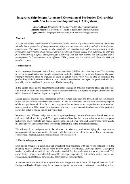
<strong>Integrated</strong> <strong>ship</strong> <strong>design</strong>: <strong>Automated</strong> <strong>Generation</strong> <strong>of</strong> <strong>Production</strong> Deliverables<br />
with New <strong>Generation</strong> Shipbuilding CAD Systems<br />
Abstract<br />
Vittorio Bucci, University <strong>of</strong> Trieste, Trieste/Italy, vbucci@units.it<br />
Alberto Marinò, University <strong>of</strong> Trieste, Trieste/Italy, marino@units.it<br />
Igor Juricic, Intergraph, Milano/Italy, igor.juricic@intergraph.com<br />
It is considered the possible level <strong>of</strong> automation for the outputs <strong>of</strong> production deliverables obtainable<br />
with the latest generation <strong>of</strong> computer-aided <strong>design</strong> systems dedicated to <strong>ship</strong> and <strong>of</strong>fshore <strong>design</strong> and<br />
construction. The paper points out the possibility <strong>of</strong> ensuring fast and accurate updates <strong>of</strong> the<br />
production deliverables when changes during the <strong>design</strong> process occur. With reference to stiffened<br />
plate structures <strong>of</strong> a typical hull appendage, a series <strong>of</strong> tests has been carried out, considering both a<br />
homogenous CAD environment and different CAD systems that externalize their data via XML for<br />
interface reasons.<br />
1. Introduction<br />
In the <strong>ship</strong> acquisition process the <strong>design</strong> phase immediately follows the planning phase. The planning<br />
involves different activities, mainly concerning with the strategy <strong>of</strong> a certain business. Different<br />
strategic objectives shall be analyzed in order to define which vessel will be able to maximize the<br />
pr<strong>of</strong>itability <strong>of</strong> the investment. Here is taken the decision whether the <strong>ship</strong> to be purchased will be a<br />
new <strong>ship</strong> or a second-hand/converted/modified existing <strong>ship</strong>.<br />
In the <strong>design</strong> phase all the requirements and needs stressed in previous planning phase are collected,<br />
and proper solutions are proposed in order to establish efficient configuration, shape, dimensions and<br />
other characteristics <strong>of</strong> the <strong>ship</strong> to be acquired.<br />
Design process involves also engineering activities where structures are defined and the components<br />
<strong>of</strong> the various systems to be fitted are selected. It shall be considered that different conflicting aspects<br />
<strong>of</strong> the <strong>design</strong> theme shall be faced, and, in general by an iterative and repetitive stepwise method,<br />
proper solutions will be found. In this manner the convergence towards final review <strong>of</strong> the project is<br />
assured in order to realize the definitive product.<br />
Nowadays, the different <strong>design</strong> steps can be sped up through the use <strong>of</strong> computer-based tools more<br />
and more linked and integrated. The opportunities <strong>of</strong>fered by the current advance <strong>of</strong> the computer<br />
technology allow multiple and deeper investigations in a shorter time, and so improving significantly<br />
the efficiency <strong>of</strong> the entire process, to be more competitive in the global marketplace.<br />
The efforts <strong>of</strong> the <strong>design</strong>ers are to be addressed to obtain a product satisfying the <strong>ship</strong> owner's<br />
requirements at minimum costs. Obviously, all the costs involved in the <strong>ship</strong>'s life cycle (<strong>design</strong>,<br />
construction, operating and support costs) are to be considered.<br />
2. The <strong>ship</strong> <strong>design</strong> process<br />
Ship <strong>design</strong> process is a quite long and articulated path beginning with the results obtained from the<br />
planning analysis and that finishes when the new product is delivered. Drawings and/or 3D computer<br />
models, specifications and all the information needed for the production are to be elaborated. The<br />
entire <strong>design</strong> process is subdivided into different stages separated by intervals in which reviews are<br />
issued and deliverables are developed as references for the next stage.<br />
A manner to collect the various stages <strong>of</strong> the <strong>ship</strong> <strong>design</strong> process is that to distinguish between Basic<br />
Design and Product Engineering. In the basic <strong>design</strong> the <strong>ship</strong> is treated in its entirety and <strong>design</strong>ed on
a system-by-system basis, while in the product engineering the deliverables developed in the previous<br />
phase are detailed into a form suitable for the production techniques to be adopted by the <strong>ship</strong>builder.<br />
In the <strong>ship</strong> <strong>design</strong> process a stage particularly demanding is the one named Functional Design, where<br />
each system <strong>of</strong> the <strong>ship</strong> is fully defined and all its components are selected and sized, also complying<br />
with the requirements imposed by the <strong>ship</strong> owner and the regulatory bodies. The functional <strong>design</strong><br />
stage, being system oriented, can be seen as the final stage <strong>of</strong> the basic <strong>design</strong> phase. Alternatively, it<br />
can be seen also as the first stage <strong>of</strong> the production engineering phase, because it concerns with<br />
activities that are preparatory for the detailing <strong>of</strong> the systems onboard. In Fig.1 this option for the<br />
functional <strong>design</strong> stage is depicted, along with the other stages <strong>of</strong> the <strong>ship</strong> <strong>design</strong> process.<br />
Fig.1: Ship <strong>design</strong> process<br />
In the basic <strong>design</strong> phase the following stages can be distinguished:<br />
• Concept Design, where the <strong>ship</strong> owner's requirements in terms <strong>of</strong> mission and main<br />
performances <strong>of</strong> the <strong>ship</strong> are refined in strict collaboration with <strong>design</strong>ers. The latter have<br />
here the task to perform a technical feasibility analysis along with an economic analysis in<br />
order to elaborate various syntheses from which draw a practical <strong>ship</strong> <strong>design</strong> solution within<br />
the <strong>ship</strong> owner's budget.<br />
• Preliminary Design, where the vessel conceived with a few broad lines in the previous stage<br />
begins to assume specific features. Ship size and overall configuration are established, major<br />
components <strong>of</strong> the <strong>ship</strong> are selected and simple single-line diagrams for each system are<br />
traced. Thus a refined technical feasibility analysis can be carried out and assessed. The toplevel<br />
<strong>ship</strong> performances are quantified, while the secondary ones are just outlined to be later<br />
on investigated. The level <strong>of</strong> detail reached in this stage shall be sufficient to estimate<br />
construction, operating and support costs in order to finalize the economic feasibility <strong>of</strong> the<br />
investment. Moreover, a generic build strategy (reflecting only block and zone definitions to<br />
be employed during <strong>ship</strong> construction, while the sequence <strong>of</strong> assembling will be later defined)<br />
is drafted. At the end <strong>of</strong> the preliminary <strong>design</strong>, analyses aimed to reduce or eliminate major<br />
technical, cost and schedule risks are carried out.<br />
• Contract Design, which concerns with the development <strong>of</strong> a set <strong>of</strong> documents useful to<br />
accurately describe the <strong>ship</strong> to be built and to avoid misunderstanding between the parties<br />
(<strong>ship</strong> owner and <strong>ship</strong>builder) involved. Specifically, it will be issued a contract and a technical<br />
specification along with explanatory drawings. Usually, there is an accepted hierarchy among
these documents: the contract prevails on the specification, which in turns prevails on<br />
drawings. In the specification, taking also into account the preferences <strong>of</strong> both the <strong>ship</strong> owner<br />
and the <strong>ship</strong>builder, the main characteristics <strong>of</strong> the <strong>ship</strong> are listed and all the systems onboard<br />
are described and defined in their size and performances. Particular attention will be paid to<br />
ensure that there are no conflicting requirements between the various sections <strong>of</strong> the<br />
specification and the related drawings. General arrangement can be considered the most<br />
important drawing developed in this stage because it is the point <strong>of</strong> reference for the different<br />
systems fitted on <strong>ship</strong>board. Purchase technical specifications <strong>of</strong> the main machinery are in<br />
general early issued, in consideration <strong>of</strong> their long lead time. The build strategy sketched in<br />
the preliminary <strong>design</strong> is now reviewed and definitely established (block, zone and assembly<br />
sequence). Moreover, the <strong>ship</strong> production plan, reporting the <strong>ship</strong> assembly schedule, is set.<br />
• Functional Design, where <strong>design</strong> calculations and configuration <strong>of</strong> the various systems are<br />
completed. In particular, detailed naval architectural calculations are performed, the hull<br />
scantlings are developed and piping, electrical wiring, vent ducting are sized and the system<br />
routings are traced in a preliminary way. Material quantities and weights are tabulated system<br />
by system, and the first revision <strong>of</strong> the budget control list is issued. Purchase technical<br />
specifications not drawn up in the previous contract <strong>design</strong> stage are now issued, while<br />
purchase order specifications for the main machinery already considered (during the contract<br />
<strong>design</strong> stage) are addressed to vendors. Finally, this stage is concluded when <strong>ship</strong> owner and<br />
regulatory bodies’ approvals are achieved.<br />
The Product Engineering phase, being mainly a detail <strong>design</strong> phase oriented to production, can be<br />
divided into the following stages:<br />
• Transition Design, where the system-oriented information collected in the previous stages is<br />
arranged into zone-oriented information. The <strong>ship</strong> is divided into a certain number <strong>of</strong> zones in<br />
accordance with the build strategy already established, and yard plans are generated in order<br />
to efficiently organize the production work. For each zone two sets <strong>of</strong> yard plans are<br />
elaborated: one concerning the detailing <strong>of</strong> the structures and another one concerning the<br />
positioning <strong>of</strong> all systems' components (no matter how small) to be fitted in the zone<br />
considered. The merging <strong>of</strong> the hull's yard plans with the systems' yard plans makes the zone<br />
composite arrangement up. Through the yard plans it is possible to elaborate a list <strong>of</strong> materials<br />
to be used in the zone as well as evaluate weight and centre <strong>of</strong> gravity <strong>of</strong> the zone. The main<br />
objective <strong>of</strong> the zone composite arrangement drawings is that to detect if any interference<br />
(between either the various systems or systems and structures) occurs.<br />
• Work Instruction Design, which is the most pertinent stage addressed to production. In fact,<br />
instructions to manufacture the various parts <strong>of</strong> the <strong>ship</strong> (systems and structures) and how to<br />
fit them together are given, also in accordance both with the established build strategy and<br />
with the technologies adopted by the <strong>ship</strong>builder. Therefore, manufacturing work instruction<br />
drawings and fitting work instruction drawings shall be prepared. The components <strong>of</strong> the<br />
various systems in a certain zone are now grouped on a kind basis (for example, pipe pieces,<br />
ventilation duct pieces, supports, etc.), and manufacturing work instructions sufficiently<br />
detailed are given piece by piece (regardless <strong>of</strong> where they are to be manufactured). The next<br />
step involves the preparation <strong>of</strong> fitting work instructions that permit to assembly the blocks<br />
with the different items previously manufactured. In order to facilitate either the<br />
manufacturing or the fitting work, consistent material lists are prepared (i.e., material lists for<br />
manufacturing and material lists for fitting).<br />
3. The role <strong>of</strong> the computer s<strong>of</strong>tware in the integrated <strong>design</strong> process<br />
Nowadays the usage <strong>of</strong> efficient and coordinated computer-based tools in the <strong>ship</strong> <strong>design</strong> and<br />
construction process represents an important aspect to evaluate the commercial competitiveness <strong>of</strong> a<br />
<strong>ship</strong>builder. In fact, by means <strong>of</strong> such tools quicker responses to <strong>ship</strong>-owner’s requests for quotations<br />
can be given. Moreover, the accuracy <strong>of</strong> the deliverables shall be increased.
Design modifications can be performed in a more flexible way, ensuring also high level <strong>of</strong><br />
consistency. The possibility to create computer simulations with a 3D product model allows the<br />
enhancement <strong>of</strong> the activities related to both concurrent engineering and production planning. Cost<br />
control analyses are improved, and rational and timely materials and outfit acquisitions are permitted.<br />
Obviously, all these computer-based activities need a common database that should be continuously<br />
updated in order to always get reliable information. Computer-aided functions involved in the <strong>ship</strong><br />
<strong>design</strong> and production process deal with synthesis modelling, <strong>design</strong> (CAD), engineering (CAE),<br />
manufacturing (CAM), product model, computer integrated manufacturing (CIM) and computer<br />
systems integration.<br />
The traditional way to perform the <strong>ship</strong> <strong>design</strong> and construction process is essentially based on the<br />
following classes <strong>of</strong> programs:<br />
• Computer-Aided Synthesis Modelling can be considered the starting point to define a baseline<br />
on which successively the preliminary <strong>design</strong> <strong>of</strong> the vessel is developed. Specifically, the<br />
<strong>design</strong> data are elaborated taking into consideration either a parent <strong>ship</strong> or a number <strong>of</strong> similar<br />
<strong>ship</strong>s. The outputs obtained may concern <strong>design</strong>, operation or cost issues.<br />
• Computer-Aided Design (CAD) represents the natural evolution consequent to the<br />
introduction <strong>of</strong> the computer in the elaboration <strong>of</strong> drawings. Although the most <strong>of</strong> drawings<br />
are traced on a computer monitor, the final outputs are still printed on paper. The trend <strong>of</strong> the<br />
modern CAD systems is oriented towards 3D models, so that operators can have a more direct<br />
perception <strong>of</strong> what they are creating.<br />
• Computer-Aided Engineering (CAE) programs enable the various calculations inherent in the<br />
<strong>design</strong> process. There are CAE programs dedicated to specific tasks (for instance, hydrostatics<br />
and stability, weight and centres, speed/power, structure, pipe sizing, electric loading,<br />
seakeeping, noise, etc.), but modern CAE programs are <strong>of</strong>ten made-up <strong>of</strong> different modules<br />
(each for a specific task) linked to each other. Some CAE programs are specifically dedicated<br />
to give quick responses to <strong>ship</strong> owner's inquires. They draw a proper database from which<br />
parametric relation<strong>ship</strong>s can be derived in order to set up an initial <strong>design</strong> and then perform<br />
preliminary cost estimation, useful to carry out the subsequent trade-<strong>of</strong>f analyses.<br />
• Computer-Aided Manufacturing (CAM) programs represent the tools that allow the transition<br />
from the <strong>design</strong> towards the construction <strong>of</strong> the <strong>ship</strong>. In other terms, all the outcomes obtained<br />
in the stages regarding the functional <strong>design</strong> are now developed and converted pro the<br />
construction activities (e.g. welding, cutting, painting, lifting, bending, forming, planning and<br />
monitoring). An important aspect that a CAM system should have is the ability to elaborate<br />
the necessary digital data in a consistent manner with the <strong>ship</strong>yard facilities and standards.<br />
Fig.2: Ship <strong>design</strong> and construction process according to the traditional way<br />
An alternative approach to the traditional computer-based tools is given by the Product Model<br />
Programs, which include both CAD, CAE and (in some extent) CAM capabilities. The great merit <strong>of</strong><br />
such programs lies in their 3-dimensionality. In fact, users work with a 3D model since the earliest<br />
stages <strong>of</strong> the <strong>design</strong>, against the traditional approach where the work is performed in 2D in the
preliminary stages and then is extended to 3D in the detailing stages. The Product Model Programs<br />
permit also to simultaneously carry out different tasks within a multi-user environment. In such a way<br />
it is quite easy to check interior spaces (with particular attention to maintenance clearance) or<br />
interference existing between structures and outfitting. Moreover, an important aspect to be<br />
considered is that the different tasks can be performed only with the dedicated modules belonging to<br />
the same Product Model Program. In other words, there is no integration with the modules <strong>of</strong> different<br />
Product Model Programs (such a capability, instead, is obtained by the Computer Systems Integration,<br />
hereunder treated).<br />
Fig.3: Ship <strong>design</strong> and construction process based on Product Model Program<br />
A still more advanced approach than Product Model Programs is that provided by Computer-<br />
<strong>Integrated</strong> Manufacturing (CIM) programs. The latter could be seen as enhanced Product Model<br />
Programs, especially for the manufacturing activities, and with the considerable capability <strong>of</strong><br />
coordinating stand-alone programs that are interfaced with a common database. However, the standalone<br />
programs need to be tailored to comply with the individual <strong>ship</strong>yard's facilities, technologies<br />
and standards. Within a CIM environment, owing to the common database, the management <strong>of</strong><br />
information between technical and administrative divisions is thoroughly consistent. Further<br />
important feature is represented by the possibility to manage the data states in accordance with the<br />
different decision-making levels existing in the hierarchical organization <strong>of</strong> the <strong>ship</strong>yard.<br />
Fig.4: Ship <strong>design</strong> and construction process based on Computer-<strong>Integrated</strong> Manufacturing<br />
A challenge for the <strong>ship</strong>building industry is represented by Computer Systems Integration. The<br />
achievement <strong>of</strong> the fully integration among different computer systems allows the link <strong>of</strong> different<br />
organizations, all aimed to the same project. While a CIM program is calibrated only in accordance<br />
with the capability <strong>of</strong> a specific <strong>ship</strong>yard, the Computer System Integration involves many figures<br />
(i.e., <strong>ship</strong>yards, <strong>ship</strong>-owners, suppliers, classification societies, regulatory bodies and so on).<br />
Obviously, a common database should be shared among the various figures, in order to allow them to<br />
always work with reliable and consistent information.
Fig.5: Ship <strong>design</strong> and construction process based on Computer Systems Integration<br />
4. The infrastructure to support the <strong>Integrated</strong> Design<br />
To achieve major productivity and cost efficiency, improvements in the segments <strong>of</strong> the vertical<br />
process are beneficial, but are not sufficient: a solution that can manage the rate <strong>of</strong> speed <strong>of</strong> changes is<br />
required. Intergraph’s information management solution provides a collaborative tool able to ensure<br />
that valid, consistent, and high-quality engineering data is shared between applications and users<br />
when and where it is needed.<br />
Fig.6: Suite <strong>of</strong> data-centric <strong>design</strong>, engineering and information management applications<br />
A broader horizontal strategy is needed that extends through the engineering, business, material<br />
management, production, and lifecycle management domains. Considering the complexity <strong>of</strong> the<br />
process, and the fact that there is no single tool able to cover all <strong>of</strong> its facets, an open solution should<br />
be found. Such a solution should be able to both manage the communication among the various<br />
authoring tools and follow the evolution <strong>of</strong> the <strong>design</strong> and the engineering due to the change requests<br />
coming from each participant (<strong>design</strong>ers, owners, builders, regulatory and classification bodies).<br />
The capital Product Lifecycle Management (cPLM) is an open, scalable solution that can serve as a<br />
platform for the integration and data repository functions, where global project information can be<br />
created, managed, reused and controlled throughout the product lifecycle. It provides a mechanism for<br />
marine industries to use one or more products from own suite in conjunction with a number and<br />
variety <strong>of</strong> third party tools that can be integrated through the platform. The solution supports global<br />
collaboration between clients, contractors and suppliers, and helps business processes that share<br />
common information. These overarching and collaborative workflows through internal and external<br />
value chains deliver quality information to the desktop, regardless <strong>of</strong> the source application, forming a<br />
single source <strong>of</strong> access to the engineering data <strong>of</strong> the <strong>ship</strong> or the marine asset. In such a way it is<br />
ensured a reliable support to regulatory reviews, as well as to enhanced decisions by means <strong>of</strong> crossdiscipline,<br />
cross-referenced data and indices.
Fig.7: Role <strong>of</strong> the specific application portal to utilize consolidated data at enterprise level<br />
The total integration <strong>of</strong> the engineering data in a single-source data entry enables quick identification<br />
and resolution <strong>of</strong> potential problems; timely information and project reporting with seamless interfaces<br />
for corporate financial, accounting and planning applications are so guaranteed.<br />
5. Smooth and flexible transition through <strong>design</strong> phases<br />
Intergraph has partnered with world-leading and innovative best-practice <strong>ship</strong>builders to provide a<br />
next-generation fully integrated 3D modeller, in which structural and outfitting tasks are carried out<br />
by a “seamless” process through basic <strong>design</strong>, detailed <strong>design</strong>, and construction phases without the<br />
need <strong>of</strong> any re-modelling. Changes <strong>of</strong> the hull form or other plate systems trigger the automatic<br />
update <strong>of</strong> the involved hull structures and (after a specific permission) <strong>of</strong> the outfitting components<br />
related to the modified structures. Structural openings for pipe/duct/cableway penetrations are all<br />
generated automatically in accordance with rules concerning the tightness <strong>of</strong> the plate system and the<br />
compartment/zone type.<br />
The above mentioned automatic update, in addition to save time, provides consistent accuracy and<br />
improves <strong>design</strong> quality, and has a beneficial influence both on production processes and on<br />
schedules. Moreover, a more comprehensive basic <strong>design</strong> can be performed with shorter overall<br />
delivery times.<br />
5.1 Basic Design<br />
SmartMarine 3D represents an advanced marine asset and <strong>ship</strong> <strong>design</strong> s<strong>of</strong>tware <strong>of</strong>fered by Intergraph.<br />
Various SmartMarine tasks are activated to generate the functional/system view <strong>of</strong> the <strong>design</strong>. The<br />
common objective is to use a unique product model <strong>of</strong> the <strong>ship</strong>/floater for all early <strong>design</strong> tasks in<br />
order to perform strength assessment, hydrostatics, stability analyses and other naval architectural<br />
calculations, as well as specific engineering analyses for piping, HVAC and electrical systems.<br />
Tools and features for preliminary <strong>ship</strong>/marine <strong>design</strong> include:<br />
• A complete 3D digital product model that should be considered as the "master" and the<br />
unique valid source <strong>of</strong> information for all the life-cycle applications.<br />
• A rule-driven structural <strong>design</strong> in order to support all arrangements, connections and block<br />
divisions.<br />
• Flexibility to select the hull and surfacing <strong>design</strong> tools, as well as the ability to exchange<br />
compartment data received from other well-known initial <strong>design</strong> packages, such as NAPA.<br />
• The idealisation <strong>of</strong> the model that, in addition to the hydrostatic and hydrodynamic<br />
calculations, can be used for the finite-element analyses (FEA) by solvers as ANSYS, Nastran
(MSC) or Sestre (DNV). So that a fast assessment <strong>of</strong> the vessel structure is allowed, and the<br />
optimization <strong>of</strong> the solution (with respect to any <strong>design</strong> objective) adopted is facilitated.<br />
• Comprehensive equipment, piping, structure and space management functions. Different piperun<br />
interfaces are available as direct user input, import from spreadsheets or Piping and Instrumentation<br />
Diagram (P&ID). User-defined layout <strong>design</strong> rules can be used to monitor and,<br />
where necessary, to enforce industry or <strong>design</strong> standards for the equipment placement, piping<br />
configuration and spacing. In addition, for a given layout, an integrated pipe AutoRouter calculates<br />
and displays the pipe routes with the lowest possible cost complying with the applied<br />
<strong>design</strong> standards.<br />
• <strong>Automated</strong> definition <strong>of</strong> drawings and reports, including bulk materials quantities reports for<br />
cost estimation purposes.<br />
•<br />
Fig.8: Aft part <strong>of</strong> a <strong>ship</strong> emphasizing structural vs outfitting content<br />
To perform strength assessment based on classification rules or other structural analyses it is assumed<br />
that the solution will make available the model and the associated properties to the CAE system without<br />
having to add <strong>design</strong> efforts or to re-model. A robust and efficient interface is needed to manage<br />
exceptions and to overcome to possible data inconsistency issues, since the CAD model have to be<br />
simplified without losing correctness from the perspective <strong>of</strong> the analysis tool.<br />
An Application Programming Interface (API) approach combined with XML has been used to interface<br />
the SmartMarine 3D structures with a section scantlings s<strong>of</strong>tware (Nauticus by DNV). There is<br />
also an interface with Sesam GeniE (by DNV).<br />
Fig.9: The interface allowing CAD model to be used by analysis tools
In the development <strong>of</strong> the interface an important step is the transformation from the internal object<br />
model to a suitable model for exchange <strong>of</strong> data between different applications (i.e., create the "exchange<br />
model" to be used by the solution integrator). The exchange model does not contain the complete<br />
internal object model, but only data <strong>of</strong> interest for the integration, in particular it describes the<br />
structure and the format <strong>of</strong> the data to be exchanged. In parallel, the interface needs another model<br />
where to describe how to interpret the treated data. This is the "reference model" that inherits the exchange<br />
model and adds semantics to enable interpretation <strong>of</strong> the data, so allowing an effective exchange<br />
<strong>of</strong> "models" between collaborating applications.<br />
Clearly, in this manner redundant modelling are eliminated and possible errors are reduced, moreover<br />
the classification and the whole approval process is sped up.<br />
5.2 Product Engineering and Planning<br />
The ability <strong>of</strong> SmartMarine 3D <strong>of</strong> treating the vessel model as a whole in all the phases <strong>of</strong> the <strong>design</strong><br />
along with the integration with planning tasks gives the <strong>design</strong>-to-production approach a considerable<br />
competitive advantage. As a matter <strong>of</strong> fact, it is able to automatically generate up to 90% <strong>of</strong> the<br />
structural details starting from the functional model and more than 95% <strong>of</strong> manufactured parts from<br />
the detailed model. The <strong>design</strong> intent is attained via <strong>design</strong> rules and relation<strong>ship</strong>s between structural<br />
and outfitting items. The increased overall data quality and integrity helps to retain engineering and<br />
corporate knowledge for future applications.<br />
Building blocks are defined in the earliest stages <strong>of</strong> the <strong>design</strong>. The assembly planning task, besides<br />
weights and centres <strong>of</strong> gravity, enables to define the assembly orientation, foot-print and mounting<br />
sequence, which are pre-requisites for the automatic generation <strong>of</strong> the building instructions for the<br />
workshop, as well as for plotting dedicated assembly drawings. In particular, the task enables the<br />
definition <strong>of</strong> assembly and sub-assembly structures, specifies the work-centre assignments and<br />
determines the assembly sequencing. Without rework, all this information will be refined up to the<br />
lowest level during the progress <strong>of</strong> the project.<br />
A building simulation can be performed at any stage <strong>of</strong> the project with planning data linked to<br />
schedule information (master and procurement) in order to check the alignment with the building<br />
strategy. The links with external/third party planning and scheduling systems are easily made,<br />
especially with MS OLE-enabled applications. Such a tight integration makes changes and updates to<br />
schedules extremely simple. Furthermore, logistics for materials distribution is greatly improved.<br />
6. Automation in the generation <strong>of</strong> deliverables at any <strong>design</strong> stage<br />
Proper filters allow the retrieving <strong>of</strong> specific data from the relational database and their visualization<br />
in a user-friendly manner during the <strong>design</strong>-to-production process, without writing complex queries.<br />
All the deliverables, as drawings and reports, are generated by a similar procedure: i.e., extracted via<br />
implicit queries and then re-symbolized to fit industry standards or requirements <strong>of</strong> customized<br />
representations, at any time.<br />
Typical piping isometric sketches or pipe-support manufacturing drawings or pr<strong>of</strong>ile sketches are<br />
generated out-<strong>of</strong>-the-box and no end-user touch-up is expected. Scantling drawings <strong>of</strong> blocks and<br />
their plate systems are also automatically generated, usually following the ISO128-25 standard.<br />
General Arrangement drawings, as the Plot Plan shown below, have to consider the addition <strong>of</strong><br />
limited touch-up (additional labels or dimensions) by the end-user, touch-up that will be anyhow<br />
noted in case <strong>of</strong> changes to the model, as if they were automatically generated by the system.
Fig.10: Flow-diagrams showing object re-symbolization in drawing generation process<br />
7. Test case<br />
Fig.11: Plot Plan <strong>of</strong> a platform and scantling drawing <strong>of</strong> a deck<br />
During Spring 2012 at the Department <strong>of</strong> Engineering and Architecture, Division <strong>of</strong> Naval<br />
Architecture, <strong>of</strong> the University <strong>of</strong> Trieste started an education program on <strong>ship</strong> integrated <strong>design</strong> using<br />
SmartMarine 3D and a number <strong>of</strong> third-party applications to simulate a <strong>design</strong>-to-production process.<br />
The main target <strong>of</strong> such an education program was that to apply commercial tools both in the <strong>design</strong><br />
and in the generation <strong>of</strong> deliverables during the complete <strong>design</strong> process <strong>of</strong> a typical hull appendage.<br />
The <strong>design</strong> <strong>of</strong> a semi-spade rudder has been carried out, and the management <strong>of</strong> a major change in<br />
dimensions has been also checked.<br />
7.1 The transfer <strong>of</strong> the model towards programs for specific analyses<br />
The question <strong>of</strong> linking between systems (in practice the exchanging data) implies the identification<br />
<strong>of</strong> comprehensive information to be given in a proper format and content. Although there is a series <strong>of</strong><br />
standards for data exchange, their applicability is limited, because the more functional the standard is,<br />
the more complex its use is and the more expensive it becomes. The universality required from the<br />
standard for data exchange represents an additional difficulty for an efficient data transfer. For the<br />
reasons specified, the so-called “point-to-point” solutions are the optimum for the linkage when the<br />
two systems to be connected are known. A detailed data description from a particular system is an<br />
essential prerequisite for the achievement <strong>of</strong> such an interface, and the presentation <strong>of</strong> the data using
the XML facilitates the understanding by the receiving system.<br />
TRIDENT (by USCS, Uljanik Shipbuilding Computer System) is a system whose basic task is to<br />
complement the CAD/CAE systems in specific areas where, by means <strong>of</strong> its specialised internal<br />
modules, makes it possible to increase the completeness or the efficiency <strong>of</strong> the overall <strong>design</strong>-toproduction<br />
work. The TRIDENT system is already an integrated solution with individual modules (for<br />
instance Painting and Nesting) having a great functionality, which makes attractive the interfacing<br />
with other CAD systems as well.<br />
By the test case performed the development <strong>of</strong> the programming interface (API) for data exchange<br />
between Intergraph SmartMarine 3D structural elements and the TRIDENT modules has been<br />
checked and refined. Prerequisite for such a development was that both systems had well established<br />
mechanisms for data exchange based on XML. The technology uses XSD data schema and allows a<br />
fast and simple definition <strong>of</strong> the connections between systems, together with adapting capabilities in<br />
the case <strong>of</strong> new requirements or changes.<br />
Fig.12: Flow diagram <strong>of</strong> the SmartMarine 3D → TRIDENT Nesting interface<br />
The method applied to build the API facilitates the independent updates <strong>of</strong> the s<strong>of</strong>tware on both<br />
platforms, as the uneven publishing <strong>of</strong> new revisions <strong>of</strong> s<strong>of</strong>tware represents one <strong>of</strong> the known<br />
problems in the “point-to-point” interfaces between applications.<br />
7.2 The connection between SmartMarine 3D and third-party tools in different <strong>design</strong> phases<br />
The structural modelling within SmartMarine 3D supports three different levels <strong>of</strong> element definition,<br />
depending <strong>of</strong> the phase <strong>of</strong> the project. The data in each phase are characterized by a different<br />
complexity due to the degree <strong>of</strong> details displayed. In each phase, it is possible to obtain a record <strong>of</strong> the<br />
structure data in the form <strong>of</strong> XML files. The TRIDENT modules accept and return data by means <strong>of</strong> a<br />
dedicated import/export mechanism specially developed. During the import session, each importer<br />
can generate data containing information on how transform the imported data into another format.<br />
This approach enables to combine the functionalities <strong>of</strong> SmartMarine 3D with those <strong>of</strong> a particular<br />
TRIDENT module (apart the complexity or the level <strong>of</strong> definition considered).<br />
Fig.13: SmartMarine 3D Molded Forms modelling task and TRIDENT application GUI
7.3 The interface towards generic analysis and production modules<br />
The data transfer between SmartMarine 3D (SM3D) and the TRIDENT modules has been validated<br />
using the data drawn from a rudder modelled in SmartMarine environment.<br />
Interface is made through the following phases:<br />
• During the first phase (Basic Design) the data is transferred from SM3D to TRIDENT Ship Explorer.<br />
This phase is characterized by poorly detailed elements, but good enough to carry out<br />
various analyses based on the transformation <strong>of</strong> the structural elements in finite elements. For the<br />
test case, the validation <strong>of</strong> the interface was based on a visual exam.<br />
• The second phase (Detailed Design) is the data transfer from SM3D to the module TRIDENT<br />
Painting. The elements are completely defined from the point <strong>of</strong> view <strong>of</strong> a 3D model. Because <strong>of</strong><br />
the data organization in TRIDENT Painting, the SM3D data has to be loaded in the hierarchy<br />
structure <strong>of</strong> the project/yard. The results obtained with the TRIDENT Painting module showed<br />
that the quality <strong>of</strong> the transferred SM3D elements did not differ from the ones natively obtained<br />
by the TRIDENT system.<br />
• During the third phase (Structural Manufacturing) the SM3D elements data is simplified in terms<br />
<strong>of</strong> geometry, but provided with additional attributes necessary for the production (i.e., marking,<br />
bevelling, welding, margins and dimensions inclusive <strong>of</strong> shrinkage factor). All this data is used in<br />
TRIDENT Nesting. The test case showed that the transferred elements, with some known exceptions<br />
(the bevelling data was connected with weld data, while grinding data was ignored), could<br />
be successfully nested, and the corresponding NC programs for cutting machines generated.<br />
7.4 The Finite-Element Analysis and the role <strong>of</strong> the intermediate mesh generator<br />
Another ambit <strong>of</strong> the test case has also included the transfer <strong>of</strong> the SmartMarrine 3D model towards<br />
Finite-Element Analysis (FEA) modules via a generic mesh generator named CAFE (by BVB).<br />
One <strong>of</strong> the main benefits <strong>of</strong> the integration between SmartMarine 3D and CAFE is the possibility to<br />
avoid redundant tasks and unnecessary loss <strong>of</strong> time on remodelling in FEA environment structures<br />
already defined in a CAD environment. The process is iterative and the workflow is not uniquely<br />
identified, since marine structures may require different objectives <strong>of</strong> analysis, depending on <strong>design</strong><br />
phase. Initially, at the Basic Design phase it is necessary to validate the structural dimensioning and<br />
the relation<strong>ship</strong>s among the various members. In a subsequent phase, the interface to transfer the<br />
structural model to a FEA environment has to be activated. In such a workflow the CAFE module<br />
plays the role <strong>of</strong> intelligent mesh generator able to prepare the model for the FEA solver (ANSYS for<br />
the test performed).<br />
Fig.14: The role <strong>of</strong> CAFE mesh generator and the rudder model in ANSYS<br />
In the test case the plate members have been successfully transferred, but due to CAFE limitations in<br />
treating solids (e.g. casted and forged elements) considerable touch-ups needed to get a suitable model<br />
for the FEA environment.
7.5 The interface with the production systems<br />
It has been tested the module <strong>of</strong> TRIDENT for nesting (TRIDENT Nesting). Different element types<br />
are used to define the geometry <strong>of</strong> plates in SmartMarine 3D and in TRIDENT Nesting (i.e.,<br />
SMS_PLATE_TYPE in SmartMarine 3D and Nesting element in TRIDENT, respectively). It is worth<br />
noting that the SMS_PLATE_TYPE element is more complex than the TRIDENT Nesting element.<br />
The contour <strong>of</strong> the SMS_PLATE_TYPE element is divided into several edges which in turn are<br />
defined by the CVG_CURVE through a series <strong>of</strong> vertices representing the ends <strong>of</strong> linked straightlines<br />
and arcs; moreover for each edge are also defined further properties like surface treatment<br />
(grinding) and bevelling. The TRIDENT Nesting element instead has a contour simply defined by a<br />
series <strong>of</strong> 3D points.<br />
Fig.15: Definition <strong>of</strong> the plate contour in SmartMarine 3D and in TRIDENT Nesting<br />
Therefore, the conversion <strong>of</strong> the plate contour from SmartMarine 3D to TRIDENT Nesting, involves<br />
a loss <strong>of</strong> information about the geometry <strong>of</strong> edges and their properties (grinding, bevelling). Such a<br />
deficiency is partially resolved by writing the information about the bevel <strong>of</strong> the edge to be welded<br />
next to the marking <strong>of</strong> the piece, but in this manner the grinding information is definitely lost.<br />
Fig.16: A nested raw plate in TRIDENT Nesting after import from SmartMarine 3D<br />
The test case has confirmed that plates can be transferred from SmartMarine 3D to TRIDENT Nesting<br />
without need <strong>of</strong> touch-ups, allowing also the generation <strong>of</strong> information for the NC cutting machines.<br />
All the information about the nested raw plate is returned to the engineering database via XML and/or<br />
a dedicated API routine.<br />
8. Conclusions<br />
The different phases <strong>of</strong> the <strong>ship</strong> <strong>design</strong> process have been thoroughly examined in accordance with<br />
the traditional approach, and the different categories <strong>of</strong> programs that are commonly used in each<br />
phase have been described. In order to improve significantly the efficiency <strong>of</strong> the entire process<br />
nowadays the research is addressed to an intelligent integration <strong>of</strong> the different <strong>design</strong> environments.<br />
The basic concept concerns the creation <strong>of</strong> a unique 3D model <strong>of</strong> a vessel or a platform from which<br />
attain any information to be used both in the basic <strong>design</strong> and in product engineering stage. To this<br />
end a central database is an essential pre-requisite <strong>of</strong> the system. Of course, the stored data must have<br />
a format to be intelligible by any program used in the <strong>design</strong>-to-production process (planning,<br />
scheduling and purchasing included). Moreover, such a database must be able to receive all the data<br />
changes that occur during the workflow, updating automatically the master model. The management
<strong>of</strong> the data flows should be entrusted to a program ensuring a reliable link with specialized third-party<br />
tools. An important aspect during the <strong>design</strong> process concerns the issuing <strong>of</strong> updated and consistent<br />
deliverables (drawings and reports).<br />
Moreover, an integrated environment opens the possibility for a productive cooperation in various<br />
projects between companies that work with different systems. As a matter <strong>of</strong> fact the most complex,<br />
capital projects are seldom carried out within a single company because the demanding and<br />
specialized tasks and the tight deadlines make it necessary to divide the activities among cooperative<br />
partners.<br />
Of course, the strategy based on the integration <strong>of</strong> different disciplines requires significant<br />
investments in s<strong>of</strong>tware, research and training <strong>of</strong> end-users, but it represents, own to the current state<br />
<strong>of</strong> the art, the only way to improve and shorten the overall <strong>design</strong>-to-production process.<br />
References<br />
LAMB, T. (Ed.) (2003), Ship Design and Construction, SNAME<br />
STORCH, R.L.; HAMMON, C.P.; BUNCH, H.M.; MOORE, R.C. (1995), Ship <strong>Production</strong>, Cornell<br />
Maritime Press<br />
MILANOVIĆ, M., BISTRIČIĆ, M., ŠIKIĆ, G., JURIČIĆ, I. (2012), Data exchange between CAD<br />
systems using XML, 20 th SORTA Symp., Zagreb<br />
FRANK, D., JURIČIĆ, I., BRALIĆ, S. (2012), CAFE mesher: An advanced complex FE mesh<br />
generation algorithm utilized in SmartMarine 3D environment, 11 th IMDC, Glasgow, Vol. 3, pp.335-<br />
341<br />
VELDHUIZEN, M.M.J.M., (2011), Capital Project Lifecycle Management (cPLM) vs. Product<br />
Lifecycle Mangement (PLM) for <strong>ship</strong>building, marine and <strong>of</strong>fshore industries, ICCAS, Trieste<br />
POLINI M.A., (2011), A neutral XML schema for basic <strong>design</strong> stage interface to class societies,<br />
ICCAS, Trieste<br />
RASMUSSEN, B., DAMHAUG, A.C., (2007), From basic <strong>design</strong> to strength assessment CAD-CAE<br />
integration, 6 th COMPIT, Cortona, pp.346-354