Accu LED MH - American DJ
Accu LED MH - American DJ
Accu LED MH - American DJ

You also want an ePaper? Increase the reach of your titles
YUMPU automatically turns print PDFs into web optimized ePapers that Google loves.
<strong>American</strong> <strong>DJ</strong>®<br />
<strong>American</strong> <strong>DJ</strong>®<br />
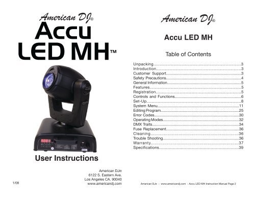
<strong>Accu</strong> <strong>LED</strong> <strong>MH</strong><br />
Table of Contents<br />
User Instructions<br />
Unpacking......................................................................3<br />
Introduction....................................................................3<br />
Customer Support......................................................................3<br />
Safety Precautions......................................................................4<br />
General Information.....................................................................5<br />
Features.........................................................................5<br />
Registration......................................................................5<br />
Controls and Functions..............................................................6<br />
Set-Up.............................................................................8<br />
System Menu............................................................................11<br />
Editing Program.........................................................................25<br />
Error Codes...............................................................................30<br />
Operating Modes.......................................................................32<br />
DMX Traits.................................................................................34<br />
Fuse Replacement....................................................................36<br />
Cleaning..................................................................36<br />
Trouble Shooting.......................................................................36<br />
Warranty.................................................................37<br />
Specifications....................................................................39<br />
1/08<br />
<strong>American</strong> <strong>DJ</strong>®<br />
6122 S. Eastern Ave.<br />
Los Angeles CA. 90040<br />
www.americandj.com<br />
<strong>American</strong> <strong>DJ</strong>® - www.americandj.com - <strong>Accu</strong> <strong>LED</strong> <strong>MH</strong> Instruction Manual Page 2
<strong>Accu</strong> <strong>LED</strong> <strong>MH</strong><br />
Introduction<br />
Unpacking: Thank you for purchasing the <strong>Accu</strong> <strong>LED</strong> <strong>MH</strong> by <strong>American</strong><br />
<strong>DJ</strong>®. Every <strong>Accu</strong> <strong>LED</strong> <strong>MH</strong> has been thoroughly tested and has<br />
been shipped in perfect operating condition. Carefully check the shipping<br />
carton for damage that may have occurred during shipping. If the<br />
carton appears to be damaged, carefully inspect your fixture for any<br />
damage and be sure all equipment necessary to operate the unit has<br />
arrived intact. In the event damage has been found or parts are missing,<br />
please contact our toll free customer support number for further<br />
instructions. Please do not return this unit to your dealer without contacting<br />
customer support first.<br />
Introduction: The <strong>Accu</strong> <strong>LED</strong> <strong>MH</strong> is a nine channel, moving head,<br />
DMX intelligent fixture. The fixture can operate in three different operating<br />
modes; stand alone, sound-active, or in a Master/Slave configuration.<br />
The <strong>Accu</strong> <strong>LED</strong> <strong>MH</strong> comes with several built in programs that<br />
can be used, while operating as a stand alone unit or when used in<br />
multiples linked in a master/slave configuration. For best results use<br />
fog or special effects smoke to enhance the beams projections.<br />
Customer Support: <strong>American</strong> <strong>DJ</strong>® provides a toll free customer<br />
support line, to provide help and to answer any question should you<br />
encounter problems during your set up or initial operation. You may<br />
also visit us on the web at www.americandj.com for any comments or<br />
suggestions. Service Hours are Monday through Friday 9:00 a.m. to<br />
5:00 p.m. Pacific Standard Time.<br />
Voice: (800) 322-6337<br />
Fax: (323) 582-2941<br />
E-mail: support@americandj.com<br />
To purchase parts online visit http://parts.americandj.com<br />
Warning! To prevent or reduce the risk of electrical shock or fire, do<br />
not expose this unit to rain or moisture.<br />
Warning! This may cause severe eye damage. Avoid looking directly<br />
into the light source at all times!<br />
<strong>Accu</strong> <strong>LED</strong> <strong>MH</strong><br />
Safety Precautions<br />
For Your Own Personal Safety, Please Read and Understand This<br />
Manual Completely Before You Attempt To Install Or Operate<br />
This Unit!<br />
• To reduce the risk of electrical shock or fire, do not expose this unit<br />
rain or moisture<br />
• Do not spill water or other liquids into or on to your unit.<br />
• Be sure that the local power outlet match that of the required voltage<br />
for your unit.<br />
• Do not attempt to operate this unit if the power cord has been<br />
frayed or broken.<br />
• Do not attempt to remove or break off the ground prong from<br />
the electrical cord. This prong is used to reduce the risk of electrical<br />
shock and fire in case of an internal short.<br />
• Disconnect from main power before making any type of connection.<br />
• Do not remove the cover under any conditions. There are no user<br />
serviceable parts inside.<br />
• Never operate this unit when it’s cover is removed.<br />
• Always be sure to mount this unit in an area that will allow proper<br />
ventilation. Allow about 6” (15cm) between this device and a wall.<br />
• Do not attempt to operate this unit, if it becomes damaged.<br />
• This unit is intended for indoor use only, use of this product outdoors<br />
voids all warranties.<br />
• Always mount this unit in safe and stable matter.<br />
• Power-supply cords should be routed so that they are not likely to<br />
be walked on or pinched by items placed upon or against them,<br />
paying particular attention to cords at plugs, convenience receptacles,<br />
and the point where they exit from the appliance.<br />
• Cleaning -The fixture should be cleaned only as recommended by<br />
the manufacturer. See page 38 for cleaning details.<br />
• Heat -This fixture should be situated away from heat sources such<br />
as radiators, heat registers, stoves, or other appliances (including<br />
amplifiers) that produce heat.<br />
• The fixture should be serviced by qualified service personnel when:<br />
A. Objects have fallen, or liquid has been spilled into the appliance.<br />
B. The appliance has been exposed to rain or water.<br />
C. The appliance does not appear to operate normally or exhibits a<br />
marked change in performance.<br />
<strong>American</strong> <strong>DJ</strong>® - www.americandj.com - <strong>Accu</strong> <strong>LED</strong> <strong>MH</strong> Instruction Manual Page 3<br />
<strong>American</strong> <strong>DJ</strong>® - www.americandj.com - <strong>Accu</strong> <strong>LED</strong> <strong>MH</strong> Instruction Manual Page 4
<strong>Accu</strong> <strong>LED</strong> <strong>MH</strong> General Information <strong>Accu</strong> <strong>LED</strong> <strong>MH</strong> Controls and Functions<br />
To optimize the performance of this product, please read these operating<br />
instructions carefully to familiarize yourself with the basic operations of<br />
this unit. These instructions contain important safety information regarding<br />
the use and maintenance of this unit. Please keep this manual with<br />
the unit, for future reference.<br />
<strong>American</strong> <strong>DJ</strong>® will not accept any liability for any resulting damages<br />
caused by the non-observance of this manual or any unauthorized<br />
modification to this unit.<br />
Caution! There are no user serviceable parts inside this unit. Do not<br />
attempt any repairs yourself, doing so will void your manufactures warranty.<br />
In the unlikely event your unit may require service please contact<br />
<strong>American</strong> <strong>DJ</strong>®.<br />
<strong>Accu</strong> <strong>LED</strong> <strong>MH</strong><br />
Features<br />
• DMX-512 Protocol Compatible (Uses Nine DMX Channels)<br />
• 3 Operating Modes - Master/Slave; Stand Alone; Sound Active<br />
• Internal Microphone<br />
• Bright 3 Watt <strong>LED</strong>s<br />
• Edit and Save Scenes into the Memory<br />
• Variable Strobe (1-12 fps)<br />
• Switchable 540˚ to 630˚ Pan Movement<br />
• 265˚ Tilt Movement<br />
• Digital Display for Address and Function Setting<br />
<strong>Accu</strong> <strong>LED</strong> <strong>MH</strong><br />
Product Registration<br />
The <strong>Accu</strong> <strong>LED</strong> <strong>MH</strong> carries a one year limited warranty. Please fill out<br />
the enclosed warranty card to validate your purchase. All returned<br />
service items whether under warranty or not, must be freight pre-paid<br />
and accompany a return authorization (R.A.) number. The R.A. number<br />
must be clearly written on the outside of the return package. A brief<br />
description of the problem as well as the R.A. number must also be<br />
written down on a piece of paper and included in the shipping carton.<br />
If the unit is under warranty, you must provide a copy of your proof of<br />
purchase invoice. You may obtain a R.A. number by contacting our<br />
customer support team on our toll free customer support number. All<br />
packages returned to the service department not displaying a R.A.<br />
number on the outside of the package will be returned to the shipper<br />
at the shippers cost.<br />
<strong>American</strong> <strong>DJ</strong>® - www.americandj.com - <strong>Accu</strong> <strong>LED</strong> <strong>MH</strong> Instruction Manual Page 5<br />
FRONT<br />
REAR<br />
1<br />
2<br />
8<br />
9<br />
3 4 5 6 7<br />
<strong>American</strong> <strong>DJ</strong>® - www.americandj.com - <strong>Accu</strong> <strong>LED</strong> <strong>MH</strong> Instruction Manual Page 6
<strong>Accu</strong> <strong>LED</strong> <strong>MH</strong><br />
Controls and Functions<br />
1. Mode/ESC Button - This button is used to exit menus and to scroll<br />
backwards through certain menus only.<br />
2. Up Button - This button is used to scroll forward when navigating<br />
through the system menu.<br />
3. Down Button - This button is used to scroll backwards when navigating<br />
through the system menu.<br />
4. Software Update Input Jack - This jack is used to update the<br />
latest software version into the unit.<br />
5. Enter Button - This button is used to select and confirm a function<br />
when working in the system menu. It is also used to exit certain<br />
menus.<br />
6. XLR Output Jack - This jack is used to transmit the incoming<br />
DMX signal to another DMX fixture, or transmit a Master/Slave signal<br />
to the next <strong>Accu</strong> <strong>LED</strong> <strong>MH</strong> in the chain. For best results in DMX or<br />
Master/Slave mode terminate this jack if it is the last unit in the chain.<br />
See “Terminator” on page 11.<br />
7. XLR DMX Input Jack - This jack is used to receive an incoming<br />
DMX signal or Master/Slave signal.<br />
8. Power Switch - This switches the power to the fixutre “On” and<br />
“Off”.<br />
9. Power Cord Inlet/Fuse Holder - This unit is equipped with a removable<br />
I.E.C. power cord. Be sure to only use the power cord included<br />
with the unit, this cord is designed to match the electrical requirements<br />
of the unit. Other cords may cause the unit to overheat or malfunction.<br />
Voltage may vary from venue to venue, when connecting this<br />
unit to a power supply be sure to connect to a matching power outlet.<br />
Never use this fixture if the ground prong has been removed or broken<br />
off. The ground prong is designed to reduce the risk of fire or electrical<br />
shock in the event the unit suffers from an internal short.<br />
The fuse housing stores a 8 amp (4 amp 220v) GMA protective fuse.<br />
Never defeat the fuse, the fuse is designed to protect the electronics in<br />
the event of severe power fluctuations. Always be sure to replace the<br />
fuse with an exact match as the one being replaced, unless otherwise<br />
told to do so by an authorized <strong>American</strong> <strong>DJ</strong>® service technician.<br />
<strong>American</strong> <strong>DJ</strong>® - www.americandj.com - <strong>Accu</strong> <strong>LED</strong> <strong>MH</strong> Instruction Manual Page 7<br />
<strong>Accu</strong> <strong>LED</strong> <strong>MH</strong><br />
Set Up<br />
Power Supply: Before plugging your unit in, be sure the source voltage<br />
in your area matches the required voltage for your <strong>American</strong> <strong>DJ</strong>®<br />
<strong>Accu</strong> <strong>LED</strong> <strong>MH</strong>. The <strong>American</strong> <strong>DJ</strong>® <strong>Accu</strong> <strong>LED</strong> <strong>MH</strong> is available in a<br />
120v and 220v version. Because line voltage may vary from venue to<br />
venue, you should be sure your unit voltage matches the wall outlet<br />
voltage before attempting to operate you fixture. Also be sure to only<br />
use the included I.E.C. power cable supplied with the unit, this cable<br />
matches the voltage and current requirements of the unit.<br />
DMX-512: DMX is short for Digital Multiplex. This is a universal protocol<br />
used by most lighting and controller manufactures as a form of<br />
communication between intelligent fixtures and controllers. A DMX<br />
controller sends DMX data instructions from the controller to the fixture.<br />
DMX data is sent as serial data that travels from fixture to fixture<br />
via the DATA “IN” and DATA “OUT” XLR terminals located on all DMX<br />
fixtures (most controllers only have a DATA “OUT” terminal).<br />
DMX Linking: DMX is a language allowing all makes and models<br />
of different manufactures to be linked together and operate from a<br />
single controller, as long as all fixtures and the controller are DMX<br />
compliant. To ensure proper DMX data transmission, when using<br />
several DMX fixtures try to use the shortest cable path possible. The<br />
order in which fixtures are connected in a DMX line does not influence<br />
the DMX addressing. For example; a fixture assigned a DMX address<br />
of 1 may be placed anywhere in a DMX line, at the beginning, at the<br />
end, or anywhere in the middle. Therefore, the first fixture controlled<br />
by the controller could be the last fixture in the chain. When a fixture<br />
is assigned a DMX address of 1, the DMX controller knows to send<br />
DATA assigned to address 1 to that unit, no matter where it is located<br />
in the DMX chain.<br />
Data Cable (DMX Cable) Requirements (For DMX<br />
and Master/Slave Operation): The <strong>Accu</strong> <strong>LED</strong> <strong>MH</strong><br />
can be controlled via DMX-512 protocol. The <strong>Accu</strong><br />
<strong>LED</strong> <strong>MH</strong> is a nine channel DMX unit. The DMX<br />
address is set electronically using the controls on<br />
the side panel of the unit. Your unit and your DMX<br />
controller require a standard 3-pin XLR connector<br />
for data input and data output (Figure 1). If you<br />
Figure 1<br />
are making your own cables, be sure to use standard two conductor<br />
<strong>American</strong> <strong>DJ</strong>® - www.americandj.com - <strong>Accu</strong> <strong>LED</strong> <strong>MH</strong> Instruction Manual Page 8
SOUND<br />
<strong>Accu</strong> <strong>LED</strong> <strong>MH</strong><br />
REMOTE<br />
CONTROL<br />
INPUT<br />
INPUT<br />
OUTPUT<br />
Set Up<br />
shielded cable (This cable may be purchased at almost all professional<br />
sound and lighting stores). Your cables should be made with a male<br />
and female XLR connector on either end of the cable. Also remember<br />
that DMX cable must be daisy chained and cannot be split.<br />
POWER<br />
Notice: Be sure to follow figures two and three when making your own<br />
DMX512<br />
cables. Do not use DMX+,DMX-,COMMON the ground lug on the XLR connector. Do not connect<br />
the cable’s shield conductor to the ground lug or allow the shield<br />
conductor to come in contact with the XLR’s outer casing. Grounding<br />
the shield could cause a short circuit and erratic behavior.<br />
SOUND<br />
REMOTE<br />
CONTROL<br />
INPUT<br />
INPUT<br />
OUTPUT<br />
POWER<br />
SOUND<br />
REMOTE<br />
CONTROL<br />
INPUT<br />
<strong>Accu</strong> <strong>LED</strong> <strong>MH</strong><br />
INPUT<br />
OUTPUT<br />
5-Pin XLR DMX Connectors. Some manufactures use 5-pin XLR<br />
connectors for DATA transmission in place of 3-pin. 5-pin XLR fixtures<br />
may be implemented in a 3-pin XLR DMX line. When inserting standard<br />
5-pin XLR connectors in to a 3-pin line a cable adaptor must be<br />
POWER<br />
used, these adaptors are readily available at most electric stores. The<br />
chart below details a proper cable conversion.<br />
Conductor<br />
Ground/Shield<br />
3-Pin XLR to 5-Pin XLR Conversion<br />
3-Pin XLR Female (Out)<br />
Pin 1<br />
5-Pin XLR Male (In)<br />
Pin 1<br />
Set Up<br />
DMX512 OUT<br />
3-PIN XLR<br />
1<br />
2<br />
3<br />
COMMON<br />
DMX +<br />
DMX -<br />
3<br />
1<br />
2<br />
DMX512 IN<br />
3-PIN XLR<br />
Figure 2<br />
3<br />
1<br />
2<br />
Data Compliment (- signal)<br />
Termination reduces signal errors and<br />
avoids signal transmission problems<br />
and interference. It is always advisable<br />
to connect a DMX terminal, (Resistance<br />
120 Ohm 1/4 W) between PIN 2 (DMX-)<br />
and PIN 3 (DMX +) of the last fixture.<br />
Data True (+ signal)<br />
Not Used<br />
Pin 2<br />
Pin 3<br />
Pin 2<br />
Pin 3<br />
Pin 4 - Do Not Use<br />
Not Used<br />
Pin 5 - Do Not Use<br />
SOUND<br />
XLR Male Socket<br />
XLR Female Socket<br />
1 Ground<br />
2 Cold 2 Cold<br />
1 Ground<br />
REMOTE INPUT OUTPUT<br />
CONTROL<br />
SOUND<br />
INPUT<br />
XLR Pin Configuration<br />
Pin 1 = Ground<br />
REMOTE<br />
CONTROL<br />
INPUT OUTPUT<br />
Pin 2 INPUT = Data Compliment (negative)<br />
3 Hot<br />
3 Hot<br />
Pin 3 = Data True (positive)<br />
Figure 3<br />
Special Note: Line Termination. When longer runs of cable are<br />
POWER<br />
POWER<br />
used, you may need to use a terminator on the last unit to avoid erratic<br />
behavior. A terminator is a 90-120 ohm 1/4 watt resistor which is connected<br />
between pins 2 and 3 of a male XLR connector (DATA + and<br />
DATA -). This unit is inserted in the female XLR connector of the last<br />
unit in your daisy chain to terminate the line. Using a cable terminator<br />
(A<strong>DJ</strong> part number Z-DMX/T) will decrease the possibilities of erratic<br />
behavior.<br />
3<br />
1<br />
2<br />
DMX512 IN<br />
3-PIN XLR<br />
3<br />
1<br />
2<br />
Termination reduces signal errors and<br />
avoids signal transmission problems<br />
and interference. It is always advisable<br />
to connect a DMX terminal, (Resistance<br />
120 Ohm 1/4 W) between PIN 2 (DMX-)<br />
and PIN 3 (DMX +) of the last fixture.<br />
Figure 4<br />
<strong>American</strong> <strong>DJ</strong>® - www.americandj.com - <strong>Accu</strong> <strong>LED</strong> <strong>MH</strong> Instruction Manual Page 9 <strong>American</strong> <strong>DJ</strong>® - www.americandj.com - <strong>Accu</strong> <strong>LED</strong> <strong>MH</strong> Instruction Manual Page 10
<strong>Accu</strong> <strong>LED</strong> <strong>MH</strong> System Menu <strong>Accu</strong> <strong>LED</strong> <strong>MH</strong> System Menu<br />
0 ADDR AXXX A001<br />
Indicate the staring DMX address<br />
A001 also is the setting for slave<br />
1 TEST T-01~T-XX Automatically test the function<br />
RUN MSTR/ALON Runs fixture as “master” or “alone” for auto<br />
2 PLAY<br />
AUDI MSTR/ALON Runs fixture as “master” or “alone” for audio<br />
AUTO Clos/ Hold/Auto/Audi Runs fixture for no DMX<br />
3 RESE<br />
ALL<br />
Reset all motors and returns fixture to home<br />
SCAN<br />
Reset only motors for pan/tilt<br />
4 TIME<br />
LIFE 0000~9999 Displays the total fixture running time<br />
CLMT<br />
Clear fixture running time<br />
5 RPAN ON/OFF Reverses the pan movements<br />
6 RTLT ON/OFF Reverses the tilt movements<br />
7 FINE ON/OFF Switch between 16 bit/8 bit<br />
8 MIC M-XX Mic sensitivity<br />
VALU D–XX D-00 (DXXX) Display the DMX512 value of each channel<br />
9 DISP D ON ON/OFF Display turn off after 2mins<br />
FLIP ON/OFF This function will reverse the display 180<br />
RDMX ON/OFF Change DMX address via external controller<br />
SPEE SP-1/SP-2 Movement Mode Select<br />
10 SPEC<br />
11 EDIT<br />
DFSE ON/OFF Resets all the fixture functions to default<br />
FEED ON/OFF Pan/tilt feedback (error correction) on/off<br />
VER V1.0~V9.9 Software version<br />
A<strong>DJ</strong>U<br />
CODE CXXX Fixture code *code is “C050”<br />
CH01~CH30 XXXX(-128~127) Motor Calibration<br />
STEP S–01 ~S–48 Set the amount of your program<br />
0 1 XX(00~FFH)<br />
C–01~C–30<br />
Edit the channels of each scene<br />
3 0 XX(00~FFH)<br />
SCXX<br />
TIME T XXX(001~999) Time for each scene<br />
CEDT ON/OFF Edit program via controller<br />
REC. RE.XX Auto Save<br />
RUN ON/OFF Program test<br />
ADDRESS MENU -<br />
AOO1 - A511 (Value) - This is where you set the DMX address of<br />
the unit.<br />
TEST MENU -<br />
T-01 - T-XX (Test) - Tests the functions of each channel. There<br />
are nine channels. Note: Some channels cannot be tested.<br />
PLAY MENU -<br />
RUN - Runs the unit as a “master” or in a stand alone mode. The<br />
unit will run a internal program mode.<br />
AUDI (Audio) - Runs the unit as a “master” or in a stand alone,<br />
sound active mode.<br />
AUTO - This is a precaution mode in case the DMX signal is lost.<br />
There are four settings to choose from:<br />
• “Hold” - This is the default setting, which in case the signal is<br />
lost the fixute will “hold” at the last setting.<br />
• “Close” - The fixture will return to its “home” standing.<br />
• “Auto” - The fixture will go into Auto mode and run a pre-programmed<br />
show.<br />
• “Audi” - The fixture will go into Sound Active mode.<br />
RESE (RESET) MENU -<br />
ALL - Resets all the motors in the unit.<br />
SCAN - Resets the motors that control pan/tilt.<br />
TIME MENU -<br />
LIFE - Displays the fixtures total running time.<br />
CLMT - Clears the fixture running time.<br />
RPAN (REVERSE PAN) MENU -<br />
ON/OFF - When “On” is chosen it will reverse the pan.<br />
<strong>American</strong> <strong>DJ</strong>® - www.americandj.com - <strong>Accu</strong> <strong>LED</strong> <strong>MH</strong> Instruction Manual Page 11 <strong>American</strong> <strong>DJ</strong>® - www.americandj.com - <strong>Accu</strong> <strong>LED</strong> <strong>MH</strong> Instruction Manual Page 12
<strong>Accu</strong> <strong>LED</strong> <strong>MH</strong><br />
RTILT (REVERSE TILT) MENU -<br />
ON/OFF - When “On” is chosen it will reverse the tilt.<br />
FINE MENU -<br />
ON/OFF - Switch between 8bit and 16bit.<br />
System Menu<br />
MIC MENU -<br />
M-01-M-70 - With this function you can make the internal mic<br />
more or less sensitive to sound.<br />
DISPLAY MENU -<br />
VALU (DMX-512 Value) - Display the DMX-512 value of each<br />
channel.<br />
D ON - Display will turn off in 2 minutes.<br />
FLIP - “Flips” the digital display 180º.<br />
SPEC MENU -<br />
RDMX - Lets you adjust the DMX address via external controller.<br />
SPEE - Lets you select the movement mode.<br />
DFSE (Default Settings) - Resets the unit to the default settings.<br />
FEED - Pan/Tilt feedback (error correction) on/off.<br />
VER (Version) - Displays the software version<br />
A<strong>DJ</strong>U - Calibration functions<br />
EDIT MENU -<br />
STEP (S-01 - S-48) - These are the steps slots that you write<br />
your programs into. There are at total of 48 steps. See edit program.<br />
SCXX (SC01 - SC30) - These are the scenes that are stored in<br />
your program. There are a total of 30 scenes.<br />
REC - This will auto save your custom program.<br />
RUN - This will run your custom program.<br />
<strong>Accu</strong> <strong>LED</strong> <strong>MH</strong><br />
System Menu<br />
On-Board System Menu. The <strong>Accu</strong> <strong>LED</strong> <strong>MH</strong> ccomes with an easy<br />
to navigate system menu. This next section will detail the functions of<br />
each command in the system menu.<br />
To access the main menu press the MODE/ESC button (7) on the front<br />
of the unit. Tap the UP (5) or DOWN (6) butons until you reach function<br />
you wish to change. When you reach the function you wish to change<br />
tap the enter button. Again, tap the UP or down buttons to change<br />
the function. Once your changes are made, tap the enter button to<br />
lock the change in the system, if the enter button is not selected<br />
within eight seconds the system will automatically return to menu section.<br />
To exit without making any changes tap the MODE/ESC button<br />
(4).<br />
ADDR MAIN MENU -<br />
ADDR DMX Address Setting via control board -<br />
1. Access the main menu.<br />
2. Tap the UP button until “ADDR” is displayed, press ENTER.<br />
4. Now the display will show “A001”. Adjust the DMX address<br />
by pressing the UP or DOWN buttons.<br />
5. Press ENTER to confirm.<br />
6. Press the MODE/ESC button to return to the main menu.<br />
When the display is on “A001”, you can directly press the UP<br />
or DN buttons to change the DMX start address.<br />
TEST MAIN MENU -<br />
TEST - This will test the functions of each channel.<br />
1. Access the main menu.<br />
2. Tap the UP button until “TEST” is displayed, press ENTER.<br />
3. The display will show “T-01”. You can now press the up<br />
button and test the different channels.<br />
<strong>American</strong> <strong>DJ</strong>® - www.americandj.com - <strong>Accu</strong> <strong>LED</strong> <strong>MH</strong> Instruction Manual Page 13<br />
<strong>American</strong> <strong>DJ</strong>® - www.americandj.com - <strong>Accu</strong> <strong>LED</strong> <strong>MH</strong> Instruction Manual Page 14
<strong>Accu</strong> <strong>LED</strong> <strong>MH</strong><br />
4. Press MODE/ESC to exit.<br />
PLAY MAIN MENU -<br />
RUN Run the unit in an Auto mode as a “master” in a<br />
Master/Slave configuration, or as a stand alone unit -<br />
1. Access the main menu.<br />
System Menu<br />
2. Tap the UP button until “PLAY” is displayed, press ENTER.<br />
3. Tap the UP button until “RUN” is displayed, press ENTER.<br />
4. Tap the UP or DOWN button to choose between “MSTR” or<br />
“ALON“, select your choice by pressing ENTER, “PASS” will flash<br />
in the display and fixture will begin its function.<br />
<strong>Accu</strong> <strong>LED</strong> <strong>MH</strong><br />
“AUDI”. “HOLD” is the default setting.<br />
System Menu<br />
5. Select the mode that you want the fixture to run in case of a<br />
lost DMX signal and press ENTER.<br />
RESE MAIN MENU -<br />
ALL - When you activate the reset function, the fixture will<br />
begin the reset motion.<br />
1. Access the main menu.<br />
2. Tap the UP button until “RESE” is displayed, press ENTER.<br />
3. Tap the UP button until “ALL” is displayed.<br />
4. Press ENTER to reset all motors, or press MODE/ESC to<br />
cancel and return to the main menu.<br />
AUDI Run the unit in Sound Active mode as a “master”, or<br />
as a stand alone unit -<br />
1. Access the main menu.<br />
2. Tap the UP button until “PLAY” is displayed, press ENTER.<br />
3. Tap the UP button until “AUDI” is displayed, press ENTER.<br />
4. Tap the UP or DOWN button to choose between “MSTR” or<br />
“ALON“, select your choice by pressing ENTER, “PASS” will flash<br />
in the display and fixture will begin its function.<br />
AUTO This is a precaution mode in case you lose the DMX<br />
signal. The fixtue has 4 modes to choose from, please see<br />
page 14 for a description of the 4 modes -<br />
SCAN - When you activate this reset function, the fixture<br />
will only reset the pan/tilt motor.<br />
1. Access the main menu.<br />
2. Tap the UP button until “RESE” is displayed, press ENTER.<br />
3. Tap the UP button until “SCAN” is displayed.<br />
4. Press ENTER to reset the pan/tilt motors, or press MODE/<br />
ESC to cancel and return to the main menu.<br />
TIME MAIN MENU -<br />
LIFE - With this function you can display the total running<br />
time of the unit.<br />
1. Access the main menu by pressing MODE/ESC button.<br />
1. Access the main menu.<br />
2. Tap the UP button until “PLAY” is displayed, press ENTER. 2. Tap the UP button until “TIME” is displayed, press ENTER.<br />
3. Tap the UP button until “AUTO” is displayed, press ENTER. 3. Tap the UP button until “LIFE” is displayed, press ENTER.<br />
4. Now <strong>American</strong> you <strong>DJ</strong>® can - www.americandj.com choose between - <strong>Accu</strong> “CLOSE”, <strong>LED</strong> <strong>MH</strong> Instruction “HOLD” Manual “AUTO”, Page or 15<br />
<strong>American</strong> <strong>DJ</strong>® - www.americandj.com - <strong>Accu</strong> <strong>LED</strong> <strong>MH</strong> Instruction Manual Page 16
<strong>Accu</strong> <strong>LED</strong> <strong>MH</strong><br />
4. Press MODE/ESC to return to the main menu.<br />
System Menu<br />
CLMT - With this function you can clear the running time of<br />
the fixture.<br />
1. Access the main menu.<br />
2. Tap the UP button until “TIME” is displayed, press ENTER.<br />
3. Tap the UP button until “CLMT” is displayed, press ENTER.<br />
4. Press ENTER to confirm.<br />
5. Press MODE/ESC to return to the main menu.<br />
RPAN MENU -<br />
RPAN - The movement of the Pan will be reversed.<br />
1. Access the main menu.<br />
2. Tap the UP button until “RPAN” is displayed, press ENTER.<br />
3. Press the UP or DOWN buttons to select either “ON” to activate<br />
this function, or “OFF” to deactivate this function.<br />
4. Press ENTER to confirm.<br />
5. Press MODE/ESC to return to the main menu.<br />
RTILT MENU -<br />
RTILT - The movement of the Tilt will be reversed.<br />
1. Access the main menu.<br />
2. Tap the UP button until “RTILT” is displayed, press ENTER.<br />
3. Press the UP or DOWN buttons to select either “ON” to activate<br />
this function, or “OFF” to deactivate this function.<br />
4. Press ENTER to confirm.<br />
5. Press MODE/ESC to return to the main menu.<br />
<strong>American</strong> <strong>DJ</strong>® - www.americandj.com - <strong>Accu</strong> <strong>LED</strong> <strong>MH</strong> Instruction Manual Page 17<br />
<strong>Accu</strong> <strong>LED</strong> <strong>MH</strong><br />
System Menu<br />
FINE MENU -<br />
FINE - This function will switch the pan/tilt between 8bit<br />
and 16bit.<br />
1. Access the main menu.<br />
3. Tap the UP button until “FINE” is displayed, press ENTER.<br />
4. Press the UP or DOWN buttons to select either “ON” to activate<br />
this function, or “OFF” to deactivate this function.<br />
5. Press ENTER to confirm.<br />
6. Press MODE/ESC to return to the main menu.<br />
DEGR MENU -<br />
DEGR - With this function you can switch the Pan degree.<br />
1. Access the main menu.<br />
2. Tap the UP button until “DEGR” is displayed, press ENTER.<br />
3. Press the UP or DOWN buttons to select either “630” or<br />
“540”.<br />
4. Press ENTER to confirm your selection.<br />
5. Press MODE/ESC to return to the main menu.<br />
MIC MENU -<br />
MIC - The internal microphone can be made more or less<br />
sensitive.<br />
1. Access the main menu.<br />
3. Tap the UP button until “MIC” is displayed, press ENTER.<br />
4. The display will show “M-01”.<br />
<strong>American</strong> <strong>DJ</strong>® - www.americandj.com - <strong>Accu</strong> <strong>LED</strong> <strong>MH</strong> Instruction Manual Page 18
<strong>Accu</strong> <strong>LED</strong> <strong>MH</strong><br />
System Menu<br />
5. Press the UP or DOWN button to adjust the microphone sensitivity<br />
between “M-01 - M-99”.<br />
6. Press ENTER to confirm when you have reached your<br />
desired microphone sesitivity level.<br />
7. Press MODE/ESC to return to the main menu.<br />
FINE MENU -<br />
FINE - This function will switch the pan/tilt between 8bit<br />
and 16bit.<br />
1. Access the main menu by pressing MODE/ESC button.<br />
3. Tap the UP button until “FINE” is displayed, press ENTER.<br />
4. Press the UP or DOWN buttons to select either “ON” to activate<br />
this function, or “OFF” to deactivate this function.<br />
5. Press ENTER to confirm.<br />
6. Press MODE/ESC to return to the main menu.<br />
MIC MENU -<br />
MIC - The internal microphone can be made more or less<br />
sensitive.<br />
1. Access the main menu by pressing MODE/ESC button.<br />
3. Tap the UP button until “MIC” is displayed, press ENTER.<br />
4. The display will show “M-01”.<br />
5. Press the UP or DOWN button to adjust the microphone sensitivity<br />
between “M-01 - M-99”.<br />
6. Press ENTER to confirm when you have reached your<br />
desired microphone sesitivity level.<br />
7. Press MODE/ESC to return to the main menu.<br />
<strong>American</strong> <strong>DJ</strong>® - www.americandj.com - <strong>Accu</strong> <strong>LED</strong> <strong>MH</strong> Instruction Manual Page 19<br />
<strong>Accu</strong> <strong>LED</strong> <strong>MH</strong><br />
DISP MAIN MENU -<br />
VALU Display the DMX-512 value of each channel -<br />
1. Access the main menu.<br />
System Menu<br />
2. Tap the UP button until “DISP” is displayed, press ENTER.<br />
3. Tap the UP button until “VALU” is displayed, press ENTER.<br />
4. The display should show “D-00”. Press the UP button in<br />
order to select the desired channel. If you select “D-05” the<br />
display will only show the DMX value of the 5th channel<br />
5. Press ENTER to confirm.<br />
6. Press MODE/ESC to return to the main menu.<br />
Now the display will change as per the 5th channel DMX<br />
value.<br />
D ON With this function “On” the display will shut off after<br />
2 minutes -<br />
1. Access the main menu.<br />
2. Tap the UP button until “DISP” is displayed, press ENTER.<br />
3. Tap the UP button until “D ON” is displayed, press ENTER.<br />
4. Press the UP or DOWN buttons to select either “ON” to activate<br />
this function, or “OFF” to deactivate this function.<br />
5. Press ENTER to confirm.<br />
6. Press MODE/ESC to return to the main menu.<br />
FLIP - This function will reverse the display 180º.<br />
1. Access the main menu.<br />
2. Tap the UP button until “DISP” is displayed.<br />
<strong>American</strong> <strong>DJ</strong>® - www.americandj.com - <strong>Accu</strong> <strong>LED</strong> <strong>MH</strong> Instruction Manual Page 20
<strong>Accu</strong> <strong>LED</strong> <strong>MH</strong><br />
3. Tap the UP button until “FLIP” is displayed, press ENTER.<br />
4. Press the UP or DOWN buttons to select either “ON” to activate<br />
this function, or “OFF” to deactivate this function.<br />
5. Press ENTER to confirm.<br />
6. Press MODE/ESC to return to the main menu.<br />
SPEC MAIN MENU -<br />
RDMX With this function you are able to change the DMX<br />
address via any DMX controller. This function is factory set<br />
to “ON” already.<br />
1. Access the main menu by pressing MODE/ESC.<br />
2. Tap the UP button until “SPEC” is displayed, press ENTER.<br />
3. Tap the UP button until “RDNX” is displayed, press ENTER.<br />
4. Press the UP button to select “ON” to activate this function,<br />
or “OFF” to deactivate.<br />
5. Press ENTER to confirm, and “PASS” will flash quickly.<br />
6. Press MODE/ESC to return to the main menu.<br />
System Menu<br />
To use this function follow the instructions:<br />
To adjust the address of your unit you must first go to the<br />
address that it is currently set to. From there you can adjust the<br />
address. First make sure all channels are set to the value of “0”.<br />
1. On your DMX controller set the DMX value of Channel 1 to<br />
the value “7”.<br />
2. Now set the DMX value of Channel 2 to the value “7” to<br />
adjust the starting address between 1 and 255. To adjust the<br />
address between 256 and 511 set Channel 2 to the value “8” .<br />
3. Set the DMX value of Channel 3 to your desired starting<br />
address. This will take about 20 seconds before the unit<br />
accepts the new DMX address.<br />
<strong>American</strong> <strong>DJ</strong>® - www.americandj.com - <strong>Accu</strong> <strong>LED</strong> <strong>MH</strong> Instruction Manual Page 21<br />
<strong>Accu</strong> <strong>LED</strong> <strong>MH</strong><br />
EXAMPLE: So, if you want the address to be 57, you must first<br />
set the address that is currently assingned to the unit. The proceed<br />
to set Channel 1s’ value to “7”, Channel 2s’ value to “7”,<br />
and Channel 3s’ value to “57”.<br />
2nd Example: Again, if you want the address to be 420, you<br />
must first set the address that is currently assingned to the unit.<br />
If you want the set the address to 420, set Channel 1s’ value to<br />
“7”, Channel 2s’ value to “8”, and Channel 3s to “164”. (256 +<br />
164 = 420)<br />
SPEE - With this function you can select the movement<br />
mode<br />
1. Access the main menu.<br />
2. Tap the UP button until “SPEC” is displayed, press ENTER.<br />
3. Tap the UP button until “SPEE” is displayed, press ENTER.<br />
4. Press the UP or DOWN buttons to select either “SP-1” or<br />
“SP-2”.<br />
5. Press ENTER to select your desired mode.<br />
DFSE - With this function you can restore the factory<br />
settings of the device. All settings will be set back to the<br />
default values. Any edited scenes will be lost. When restoring<br />
the factory settings the unit must be set to the address<br />
that the unit was in when you started editing.<br />
1. Access the main menu.<br />
2. Tap the UP button until “SPEC” is displayed, press ENTER.<br />
3. Tap the UP button until “DFSE” is displayed, press ENTER.<br />
4. The display will show “ON/OFF”.<br />
System Menu<br />
5. Press the UP button to display “ON” to activate this function,<br />
©<strong>American</strong> <strong>DJ</strong>® - www.americandj.com - <strong>Accu</strong> <strong>LED</strong> <strong>MH</strong> Instruction Manual Page 22
<strong>Accu</strong> <strong>LED</strong> <strong>MH</strong><br />
or “OFF” to deactivate this function.<br />
6. Press ENTER to confirm.<br />
7. Press MODE/ESC to return to the main menu.<br />
When you exit this function, the unit will begin to reload<br />
data.<br />
FEED - With this function you can switch the Pan/Tilt error<br />
correction on and off. This will automatically correct the<br />
Pan/Tilt if it is somehow moved out of place.<br />
1. Access the main menu.<br />
2. Tap the UP button until “SPEC” is displayed, press ENTER.<br />
3. Tap the UP button until “FEED” is displayed, press ENTER.<br />
4. Press the UP or DOWN buttons to select either “ON” to activate<br />
this function, or “OFF” to deactivate this function.<br />
5. Press ENTER to confirm.<br />
6. Press MODE/ESC to return to the main menu.<br />
VER - Use this function to display the Software version of<br />
the unit.<br />
1. Access the main menu.<br />
2. Tap the UP button until “SPEC” is displayed, press ENTER.<br />
3. Tap the UP button until “VER” is displayed, press ENTER.<br />
4. The display will show “V-1.0”, the display may also show, “V-<br />
2.0”, “V-9.9” etc.<br />
5. Press MODE/ESC to exit.<br />
System Menu<br />
<strong>Accu</strong> <strong>LED</strong> <strong>MH</strong><br />
are aligned and to adjust any motors that are not.<br />
1. Access the main menu.<br />
System Menu<br />
2. Tap the UP button until “SPEC” is displayed, press ENTER.<br />
3. Tap the UP button until “A<strong>DJ</strong>U” is displayed, press ENTER.<br />
4. Tap the UP button until “CODE” is displayed, press ENTER.<br />
5. The display will show “CXXX”, were as “XXX” represents the<br />
calibration password. The calibration password is “C050.” Use<br />
the UP or DOWN buttons to enter the proper password.<br />
6. Once the proper password is entered the display will read<br />
“CHXX”, were as “XX” represents the fixture channel number, in<br />
the case of the <strong>Accu</strong> <strong>LED</strong> <strong>MH</strong> 1~16.<br />
7. Select the desired channel to be calibrated by pressing the<br />
UP or DOWN buttons and then ENTER to confirm.<br />
8. The display will then read “xxxx”, were “xxxx” stands for<br />
the calibrate values.<br />
9. Adjust the desired calibration value between –128 and 127<br />
by pressing the UP and DOWN. As you scroll up and down<br />
through the calibration values you will<br />
notice slight changes in the wheel or motor you are attempting<br />
to calibrate.<br />
10. Once you reach your desired calibration press ENTER to<br />
confirm and lock in your calibration.<br />
11. Once you are completely finished press MODE/ESC to<br />
return to the main menu.<br />
A<strong>DJ</strong>U - Use this function is used to make sure all motors<br />
<strong>American</strong> <strong>DJ</strong>® - www.americandj.com - <strong>Accu</strong> <strong>LED</strong> <strong>MH</strong> Instruction Manual Page 23<br />
<strong>American</strong> <strong>DJ</strong>® - www.americandj.com - <strong>Accu</strong> <strong>LED</strong> <strong>MH</strong> Instruction Manual Page 24
<strong>Accu</strong> <strong>LED</strong> <strong>MH</strong><br />
Editing Program<br />
<strong>Accu</strong> <strong>LED</strong> <strong>MH</strong><br />
Editing Program<br />
EDIT - This menu item allows you to write a program into the<br />
memory (EEPROM) via the control panel or via the external<br />
controller. Please see pages 29-31 for detailed instructions.<br />
STEP - With this function you can program the number of<br />
steps in your individual Program.<br />
1. Access the main menu.<br />
2. Tap the UP button until “EDIT” is displayed, press ENTER.<br />
3. Tap the UP button until “STEP” is displayed, press ENTER.<br />
4. The display shows “S-01”, this stands for the first step of<br />
your program. You can call up to 48 scenes in “Run”. For example,<br />
if “S-05” is displayed, it means that “Run” will run the first<br />
5 scenes you saved in “Edit”.<br />
5. Press ENTER to save and press MODE/ESC to exit.<br />
SC01 - With this function you can choose the number of<br />
scenes in your Program.<br />
1. Access the main menu.<br />
2. Tap the UP button until “EDIT” is displayed, press ENTER.<br />
3. Tap the UP button until “SC01” is displayed.<br />
4. The display shows “SC01”, this stands for the first scene of<br />
your program. You can call up to 48 scenes. For example, if<br />
“SC05”, it means that “Run” will run the first 5 scenes you saved<br />
in “Edit”.<br />
5. Press ENTER to save and press MODE/ESC to exit.<br />
REC - With this function you can record the scenes automatically<br />
for the external controller.<br />
1. Access the main menu.<br />
<strong>American</strong> <strong>DJ</strong>® - www.americandj.com - <strong>Accu</strong> <strong>LED</strong> <strong>MH</strong> Instruction Manual Page 25<br />
2. Tap the UP button until “EDIT” is displayed, press ENTER.<br />
3. Tap the UP button until “REC” is displayed.<br />
4. The display shows “RE.XX”, “XX” stands for the scene<br />
number in the internal memory of where your scenes from the<br />
controller will be stored.<br />
5. Press the UP or DOWN button to select your desired scene<br />
number.<br />
6. Press ENTER to confirm, and the fixture will record the<br />
scenes from the external controller.<br />
7. Press MODE/ESC to return to the main menu.<br />
RUN With the function “RUN”, you can run your pre-made<br />
program. You can set the number of steps under Step (S-01<br />
- S-48). You can edit the individual scenes under Edit.<br />
1. Access the main menu.<br />
2. Tap the UP button until “EDIT” is displayed, press ENTER.<br />
3. Tap the UP button until “RUN” is displayed, press ENTER.<br />
4. “AUTO” is displayed. If you press the UP button it will show<br />
“SOUN”. Select which one you want to activate, and press<br />
ENTER.<br />
5. Press UP, to select “ALON” or “NAST”. Which mean stand<br />
alone, and master/slave mode.<br />
6. Select a mode, and press ENTER to confirm.<br />
7. Press MODE/ESC to return to the main menu.<br />
<strong>American</strong> <strong>DJ</strong>® - www.americandj.com - <strong>Accu</strong> <strong>LED</strong> <strong>MH</strong> Instruction Manual Page 26
<strong>Accu</strong> <strong>LED</strong> <strong>MH</strong><br />
Editing procedure 1: Using the control board only.<br />
1. Access the main menu.<br />
Editing Program<br />
2. Tap the UP button until “EDIT” is displayed. Press ENTER.<br />
3. The display will show “SCXX”, the “X” again stands for the<br />
scene number. For example, “SC01” is displayed, it means you<br />
will be editing scene 1, press ENTER. You can change the<br />
scene number by pressing the UP button.<br />
4. Press ENTER, the display will show “C-X”, the “X” again<br />
stands for the channel number. If “C-01” is displayed, you will<br />
be editing channel 1 of your selected scene, press ENTER. You<br />
can change the channel number by pressing the UP button.<br />
5. The display will show the DMX value for the channel that is<br />
being edited. It will be displayed as “11XX”, it stands for Channel<br />
11 of the editing scene, the DMX value is “XX”.<br />
6. Adjust the DMX value by pressing the UP button, until you<br />
get the expected effect for this channel.<br />
7. Press ENTER to enter the editing of the other channels of the<br />
scene.<br />
8. Repeat steps 5-8, until you finish setting all the DMX values<br />
for all the channels of this scene, each scene can have 15<br />
channels maximum.<br />
9. Once all the channels are completed, the display will flash<br />
“TIME”, this stands for the time needed to run this scene.<br />
10. Press ENTER to edit the time needed, the display shows<br />
“TXXX”, “X” stands for the time needed to run this scene. For<br />
example, “T002” means scene 1 needs 0.4 seconds to run,<br />
“T015” means scene 1 needs 3 seconds to run.<br />
11. Adjust the time needed by pressing the UP button.<br />
12. Press ENTER to save the settings for the scene you are<br />
editing, the display will change to the next scene automatically.<br />
<strong>American</strong> <strong>DJ</strong>® - www.americandj.com - <strong>Accu</strong> <strong>LED</strong> <strong>MH</strong> Instruction Manual Page 27<br />
<strong>Accu</strong> <strong>LED</strong> <strong>MH</strong><br />
Editing Program<br />
13. Repeat steps 3-12 to edit other scenes, you can edit and<br />
save 48 scenes maximum.<br />
14. Press MODE/ESC to exit, now you have edited and saved<br />
scenes using the control board. The number of steps can be<br />
defined under “Step” and the scenes can be called up under<br />
“Run”. To run the scenes see page 28.<br />
Editing procedure 2: Using an external controller (Manually<br />
record scenes one by one):<br />
1. Access the main menu.<br />
2. Select “EDIT” by pressing the UP or DOWN buttons, press<br />
ENTER.<br />
3. The display shows “SC01”.<br />
4. Press ENTER, and the display shows “C-01”.<br />
5. Select “CEDT” by pressing the DOWN button, and press<br />
ENTER.<br />
6. The display “OFF”, press the UP button so that “ON” is displayed,<br />
and press ENTER.<br />
7. The display will show “SCO2”. You have now successfully<br />
downloaded the first scene.<br />
8. Adjust the Step-time needed by pressing the UP button.<br />
9. Call up the second scene in your controller now.<br />
10. Repeat steps 7-9 until all desired scenes are downloaded.<br />
11. Press MODE/ESC to exit. The number of steps can be<br />
defined under “Step” and the scenes can be called up under<br />
“Run”.<br />
<strong>American</strong> <strong>DJ</strong>® - www.americandj.com - <strong>Accu</strong> <strong>LED</strong> <strong>MH</strong> Instruction Manual Page 28
<strong>Accu</strong> <strong>LED</strong> <strong>MH</strong><br />
Editing Program<br />
Editing procedure 3: Record the selected scenes automatically<br />
from external controller:<br />
1. Access the main menu.<br />
2. Select “EDIT” by pressing the UP or DOWN buttons, press<br />
ENTER.<br />
3. Press the UP button until the display shows “STEP”, press<br />
ENTER.<br />
4. Now adjust and set the number of steps by pressing the<br />
UP or DOWN buttons. Press ENTER to confirm the number of<br />
steps, and “PASS” will display briefly.<br />
5. Now press the DOWN button until “REC” is displayed, and<br />
press ENTER.<br />
6. The display will now show “RE.XX”, “XX” stands for the scene<br />
number in the internal memory which the scenes from the controller<br />
will be stored to. Press ENTER when you have chosen<br />
the scene number.<br />
7. Call up the scenes on the controller, and the fixture will<br />
record the scenes from the controller automatically. After the<br />
number of scenes as selected in the “STEP” menu are loaded<br />
into the fixture, it will stop the procedure and return to the previous<br />
menu.<br />
8. Press MODE/ESC to exit the “EDIT” menu and return to the<br />
main menu.<br />
<strong>Accu</strong> <strong>LED</strong> <strong>MH</strong><br />
Error Codes<br />
When power is applied, the unit will automatically enter a<br />
“reset/test” mode. This mode brings all the internal motors to a<br />
home position. If there is an internal problem with one or more<br />
of the motors an error code will flash in the display in the form<br />
of “XXer”, “XX” will represent a function number. For example,<br />
when the display shows “02Er,” it means there is some type of<br />
error with the channel 2 motor. If there are multiple errors during<br />
the start-up process they will all flash in the display. For example:<br />
if the fixtures has errors on channel 1 and channel 2 all at<br />
the same time, you will see the error message flash “01Er”, and<br />
“02Er repeated 5 times.<br />
If an error does occur during the initial start-up procedure the<br />
fixture will self-generate a second reset signal and try to realign<br />
all the motors and correct the errors, if the errors persist after a<br />
second attempt a third attempt will be made.<br />
If after a third attempt all the errors have not been corrected the<br />
fixture will make the following determinations:<br />
1) 3 or more errors - The fixture cannot function properly with<br />
three or more errors therefore the fixture will place itself in a<br />
stand-by mode until subsequent repairs can be made.<br />
2) Less than 3 errors - If the fixture has less than 3 errors, therefore<br />
most other functions will work properly. The fixture will<br />
attempt to operate normally until the errors can be corrected by<br />
a technician. The errors in question will remain flashing in the<br />
display as a reminder of internal errors.<br />
01Er – PAN movement error:<br />
If the yoke is not located in the default position after start-up or<br />
after a reset command. This message will appear after a fixture<br />
reset, if the pan-yoke’s magnetic-indexing circuit malfunctions<br />
(sensor failed or magnet is missing) or there is a stepper motor<br />
failure (defective motor or a defective motor IC drive on the<br />
main PCB).<br />
<strong>American</strong> <strong>DJ</strong>® - www.americandj.com - <strong>Accu</strong> <strong>LED</strong> <strong>MH</strong> Instruction Manual Page 29 <strong>American</strong> <strong>DJ</strong>® - www.americandj.com - <strong>Accu</strong> <strong>LED</strong> <strong>MH</strong> Instruction Manual Page 30
<strong>Accu</strong> <strong>LED</strong> <strong>MH</strong><br />
Error Codes<br />
02Er – TILT movement error:<br />
If the head is not located in the default tilt position after startup<br />
or after a reset command. This message will appear after a<br />
fixture reset, if the tilt magnetic-indexing circuit malfunctions<br />
(sensor failed or magnet is missing) or there is a stepper motor<br />
failure (defective motor or a defective motor IC drive on the<br />
main PCB).<br />
<strong>Accu</strong> <strong>LED</strong> <strong>MH</strong><br />
Operation<br />
Operating Modes: The <strong>Accu</strong> <strong>LED</strong> <strong>MH</strong> can operate in three different<br />
modes. This next section will detail the differences in the<br />
operating modes.<br />
• Stand alone mode -<br />
The unit will react to sound, or chase through the built-in programs.<br />
• Master/Slave mode -<br />
You can daisy chain up to 16 units together to get a synchronized<br />
light show without the need of an external controller. The units will<br />
react to sound or chase through the built-in programs.<br />
• DMX control mode -<br />
This function will allow you to control each individual fixtures traits<br />
with a standard DMX-512 controller such as the Elation® Show<br />
Designer. <br />
Universal DMX Control: This function allows you to use a universal<br />
DMX-512 controller such as the Elation® DMX Operator or<br />
Elation® Show Designer to control head movement, the color wheel,<br />
gobo wheel, prism, and the shutter (strobe). A DMX controller allows<br />
you to create unique programs tailored to your individual needs.<br />
1. The <strong>Accu</strong> <strong>LED</strong> <strong>MH</strong> uses sixteen DMX channels. See pages 36-37<br />
for detailed description of the DMX traits.<br />
2. To control your fixture in DMX mode, follow the set-up procedures<br />
on pages 10-12 as well as the set-up specifications that are<br />
included with your DMX controller.<br />
3. Use the controller’s faders to control the various DMX fixture traits.<br />
4. This will allow you to create your own programs.<br />
5. Follow the instruction on page 16 to set the DMX address.<br />
6. For longer cable runs (more than a 100 feet) use a terminator on<br />
the last fixture.<br />
7. For help operating in DMX mode consult the manual included<br />
with your DMX controller.<br />
Stand-Alone (Sound Active or Auto Program): This mode allows<br />
a single unit to run to the beat of the music or run through a built-in<br />
program.<br />
1. Access the main menu.<br />
2. Tap the UP button until “PLAY” is displayed, and Press ENTER.<br />
3. Tap the UP button until “AUTO” is displayed, and Press ENTER.<br />
<strong>American</strong> <strong>DJ</strong>® - www.americandj.com - <strong>Accu</strong> <strong>LED</strong> <strong>MH</strong> Instruction Manual Page 31 <strong>American</strong> <strong>DJ</strong>® - www.americandj.com - <strong>Accu</strong> <strong>LED</strong> <strong>MH</strong> Instruction Manual Page 32
<strong>Accu</strong> <strong>LED</strong> <strong>MH</strong><br />
Operation<br />
4. Press UP, to select “OFF”, “RUN”, or “AUDI”. “RUN” will make the<br />
unit run through a built-in program. “AUDI” will make the unit<br />
sound active.<br />
5. Select a mode, and press ENTER to confirm.<br />
6. Press MODE/ESC if you want to return to the main menu.<br />
7. You may change the show or invert the pan and tilt functions<br />
in the system menu by following the directions on page 22.<br />
Master-Slave Operation (Sound Active or Auto Program):<br />
This function will allow you to link up to 16 units together and operate<br />
without a controller. The units can run a built-in program or run in<br />
sound actiive mode. In Master-Slave operation one unit will act as the<br />
controlling unit and the others will react to the controlling units programs.<br />
Any unit can act as a Master or as a Slave.<br />
1. Using standard XLR microphone cables, daisy chain your units<br />
together via the XLR connector on the rear of the units. Remember<br />
the Male XLR connector is the input and the Female XLR<br />
connector is the output. The first unit in the chain (master) will use<br />
the female XLR connector only - The last unit in the chain will use<br />
the male XLR connector only. For longer cable runs we suggest a<br />
terminator at the last fixture.<br />
2. Access the main menu.<br />
2. Tap the UP button until “PLAY” is displayed, and Press ENTER.<br />
3. Tap the UP button to choose between “RUN” or “AUDI”. “RUN” will<br />
make the units run through a built-in program. “AUDI” will make<br />
the units sound active.<br />
4. Press UP, to select “ALON” or “NAST”. Which means stand alone,<br />
or master/slave mode.<br />
5. Select a mode, and press ENTER to confirm.<br />
6. Press MODE/ESC if you want to return to the main menu<br />
7. You may change the show or invert the pan and tilt functions<br />
in the system menu by following the directions on page 22.<br />
<strong>American</strong> <strong>DJ</strong>® - www.americandj.com - <strong>Accu</strong> <strong>LED</strong> <strong>MH</strong> Instruction Manual Page 33<br />
<strong>Accu</strong> <strong>LED</strong> <strong>MH</strong><br />
Channel Value Function<br />
1 0 - 255 PAN MOVEMENT 8bit<br />
2 0 - 255 PAN FINE 16bit<br />
3 0 - 255 TILT MOVEMENT 8bit<br />
4 0 - 255 TILT FINE 16bit<br />
5 SPEED OF PAN/TILT MOVEMENT<br />
0 - 255 MAX - MIN<br />
6 AUTO PROGRAMS<br />
0 - 10 BLACKOUT<br />
11 - 20 OPEN<br />
21 - 30 PROGRAM 1<br />
31 - 40 PROGRAM 2<br />
41 - 50 PROGRAM 3<br />
51 - 60 PROGRAM 4<br />
61 - 70 PROGRAM 5<br />
71 - 80 PROGRAM 6<br />
81 - 90 PROGRAM 7<br />
91 - 100 PROGRAM 8<br />
101 - 110 PROGRAM 9<br />
111 - 120 PROGRAM 10<br />
121 - 130 PROGRAM 11<br />
131 - 140 PROGRAM 12<br />
141 - 150 PROGRAM 13<br />
151 - 160 PROGRAM 14<br />
161 - 170 PROGRAM 15<br />
171 - 180 PROGRAM 16<br />
181 - 190 PROGRAM 17<br />
191 - 200 PROGRAM 18<br />
201 - 210 PROGRAM 19<br />
211 - 220 PROGRAM 20<br />
221 - 230 PROGRAM 21<br />
231 - 240 PROGRAM 22<br />
241 - 250 PROGRAM 23<br />
251 - 255 PROGRAM 24<br />
DMX Traits<br />
<strong>American</strong> <strong>DJ</strong>® - www.americandj.com - <strong>Accu</strong> <strong>LED</strong> <strong>MH</strong> Instruction Manual Page 34
<strong>Accu</strong> <strong>LED</strong> <strong>MH</strong> DMX Traits cont. <strong>Accu</strong> <strong>LED</strong> <strong>MH</strong> Fuse Replacement<br />
Channel Value Function<br />
7 PROGRAM RUNNING SPEED<br />
0 - 255 SLOW - FAST<br />
8 STROBING<br />
0 NO FUNCTION<br />
1 - 95 STROBING SLOW - FAST<br />
96 - 127 NO FUNCTION<br />
128 - 159 PULSE EFFECT IN SEQUENCES<br />
160 - 191 NO FUNCTION<br />
192 - 223 RANDOM STROBING SLOW - FAST<br />
224 - 255 NO FUNCTION<br />
9 RESET & INTERNAL PROGRAMS<br />
0 - 19 NORMAL COLOR CHANGE<br />
20 - 79 NO FUNCTION<br />
80 - 84 ALL MOTOR RESET<br />
85 - 87 SCANNER MOTOR RESET<br />
88 - 99 NO FUNCTION<br />
100 - 119 INTERNAL PROGRAM 1<br />
120 - 139 INTERNAL PROGRAM 2<br />
140 - 159 INTERNAL PROGRAM 3<br />
160 - 179 INTERNAL PROGRAM 4<br />
180 - 199 INTERNAL PROGRAM 5<br />
200 - 219 INTERNAL PROGRAM 6<br />
220 - 239 INTERNAL PROGRAM 7<br />
240 - 255 SOUND ACTIVE<br />
The fuse holder located at the rear of the unit above the power cord.<br />
Disconnect from the main power supply. Insert a standard flat head<br />
screw driver in to the fuse holder housing, located on the back of the<br />
unit. Turn the screwdriver in counter-clockwise direction to remove the<br />
fuse holder. Remove the old fuse and discard it, replace the fuse with<br />
the same type. Insert the fuse back into it’s housing.<br />
<strong>Accu</strong> <strong>LED</strong> <strong>MH</strong><br />
<strong>American</strong> <strong>DJ</strong>® - www.americandj.com - <strong>Accu</strong> <strong>LED</strong> <strong>MH</strong> Instruction Manual Page 35 <strong>American</strong> <strong>DJ</strong>® - www.americandj.com - <strong>Accu</strong> <strong>LED</strong> <strong>MH</strong> Instruction Manual Page 36<br />
Cleaning<br />
Due to fog residue, smoke, and dust cleaning the internal and external<br />
optical lenses and mirror should be carried out periodically to optimize<br />
light output. Cleaning frequency depends on the environment<br />
in which the fixture operates (I.e. smoke, fog residue, dust, dew). In<br />
heavy club use we recommend cleaning on a monthly basis. Periodic<br />
cleaning will ensure longevity, and crisp output.<br />
1. Use normal glass cleaner and a soft cloth to wipe down the outside<br />
casing.<br />
2. Use a brush to wipe down the cooling vents and fan grill.<br />
3. Clean the external optics and mirror with glass cleaner and a soft<br />
cloth every 20 days.<br />
4. Clean the internal optics with glass cleaner and a soft cloth every<br />
30-60 days.<br />
5. Always be sure to dry all parts completely before plugging the unit<br />
back in.<br />
<strong>Accu</strong> <strong>LED</strong> <strong>MH</strong><br />
Trouble Shooting<br />
Listed below are a few common problems that you may encounter,<br />
with solutions.<br />
No light output from the unit;<br />
1. Be sure you have connected your unit into a standard 120v wall<br />
outlet.<br />
2. Be sure the external fuse has not blown. The fuse is located at<br />
the rear of the unit.<br />
3. Be sure the fuse holder is completely and properly seated.<br />
Unit does not respond to sound;<br />
1. Low frequencies (bass) should cause the unit to react to sound.<br />
Tapping on the microphone, quiet or high pitched sounds may<br />
not activate the unit.
<strong>Accu</strong> <strong>LED</strong> <strong>MH</strong><br />
Warranty<br />
MANUFACTURER’S LIMITED WARRANTY<br />
A. <strong>American</strong> <strong>DJ</strong>, Inc. hereby warrants, to the original purchaser, <strong>American</strong> <strong>DJ</strong> and <strong>American</strong><br />
Audio products to be free of manufacturing defects in material and workmanship for a prescribed<br />
period from the date of purchase (see specific warranty period on reverse). This warranty shall be<br />
valid only if the product is purchased within the United States of America, including possessions<br />
and territories. It is the owner’s responsibility to establish the date and place of purchase by acceptable<br />
evidence, at the time service is sought.<br />
B. For warranty service you must obtain a Return Authorization number (RA#) before<br />
sending back the product. Contact <strong>American</strong> <strong>DJ</strong>, Inc. Service Department at 800-322-6337. Send<br />
the product only to the <strong>American</strong> <strong>DJ</strong>, Inc. factory. All shipping charges must be pre-paid. If the<br />
requested repairs or service (including parts replacement) are within the terms of this warranty,<br />
<strong>American</strong> <strong>DJ</strong>, Inc. will pay return shipping charges only to a designated point within the United<br />
States. If the entire instrument is sent, it must be shipped in it’s original package. No accessories<br />
should be shipped with the product. If any accessories are shipped with the product, <strong>American</strong> <strong>DJ</strong>,<br />
Inc. shall have no liability whatsoever for loss of or damage to any such accessories, nor for the<br />
safe return thereof.<br />
C. This warranty is void if the serial number has been altered or removed; if the product is<br />
modified in any manner which <strong>American</strong> <strong>DJ</strong>, Inc. concludes, after inspection, affects the reliability<br />
of the product; if the product has been repaired or serviced by anyone other than the <strong>American</strong> <strong>DJ</strong>,<br />
Inc. factory unless prior written authorization was issued to purchaser by <strong>American</strong> <strong>DJ</strong>, Inc.; if the<br />
product is damaged because not properly maintained as set forth in the instruction manual.<br />
D. This is not a service contract, and this warranty does not include maintenance, cleaning<br />
or periodic check-up. During the period specified above, <strong>American</strong> <strong>DJ</strong>, Inc. will replace defective<br />
parts at its expense with new or refurbished parts, and will absorb all expenses for warranty<br />
service and repair labor by reason of defects in material or workmanship. The sole responsibility<br />
of <strong>American</strong> <strong>DJ</strong>, Inc. under this warranty shall be limited to the repair of the product, or replacement<br />
thereof, including parts, at the sole discretion of <strong>American</strong> <strong>DJ</strong>. All products covered by this<br />
warranty were manufactured after January 1, 1990, and bear identifying marks to that effect.<br />
E. <strong>American</strong> <strong>DJ</strong>, Inc. reserves the right to make changes in design and/or improvements<br />
upon its products without any obligation to include these changes in any products theretofore<br />
manufactured. No warranty, whether expressed or implied, is given or made with respect to any<br />
accessory supplied with products described above. Except to the extent prohibited by applicable<br />
law, all implied warranties made by <strong>American</strong> <strong>DJ</strong>, Inc. in connection with this product, including<br />
warranties of merchantability or fitness, are limited in duration to the warranty period set forth<br />
above. And no warranties, whether expressed or implied, including warranties of merchantability<br />
or fitness, shall apply to this product after said period has expired. The consumer’s and/or Dealer’s<br />
sole remedy shall be such repair or replacement as is expressly provided above; and under no<br />
circumstances shall <strong>American</strong> <strong>DJ</strong>, Inc. be liable for any loss or damage, direct or consequential,<br />
arising out of the use of, or inability to use, this product.<br />
This warranty is the only written warranty applicable to <strong>American</strong> <strong>DJ</strong> and <strong>American</strong> Audio<br />
Products and supersedes all prior warranties and written descriptions of warranty terms and<br />
conditions heretofore published.<br />
<strong>Accu</strong> <strong>LED</strong> <strong>MH</strong><br />
MANUFACTURER’S LIMITED WARRANTY PERIODS:<br />
• All <strong>American</strong> Audio Products = 1-year (365 day) Limited Warranty (except V-Plus Series Amplifiers)<br />
• All <strong>American</strong> Audio V-Plus Series Amplifiers = 3-year (1095 day) Limited Warranty<br />
• <strong>American</strong> <strong>DJ</strong> Lighting and <strong>American</strong> <strong>DJ</strong> Branded Products = 1-year (365 day) Limited Warranty<br />
(Such as: Special Effect Lighting, Intelligent Lighting, UV lighting, Strobes, Fog Machines, Bubble<br />
Machines, Mirror Balls, Par Cans, Trussing, Lighting Stands etc. excluding Laser Products, lamps,<br />
and Star Tec Series)<br />
• <strong>American</strong> <strong>DJ</strong> Laser Products and Star Tec Products = 90-Day Limited Warranty<br />
• <strong>American</strong> <strong>DJ</strong> L.E.D. Products = 3-year (1095 day) Limited Warranty (excluding motors which<br />
have a 1-year (365 day Limited Warranty)<br />
<strong>American</strong> <strong>DJ</strong>® - www.americandj.com - <strong>Accu</strong> <strong>LED</strong> <strong>MH</strong> Instruction Manual Page 37 <strong>American</strong> <strong>DJ</strong>® - www.americandj.com - <strong>Accu</strong> <strong>LED</strong> <strong>MH</strong> Instruction Manual Page 38<br />
Notes
<strong>Accu</strong> <strong>LED</strong> <strong>MH</strong><br />
Model:<br />
Voltage*:<br />
Power Consumption:<br />
Power Draw:<br />
<strong>LED</strong>s:<br />
Dimensions:<br />
Colors:<br />
Weight:<br />
Fuse:<br />
Beam Angle:<br />
Duty Cycle:<br />
DMX:<br />
Sound Active:<br />
Working Position:<br />
Warranty:<br />
<strong>Accu</strong> <strong>LED</strong> <strong>MH</strong><br />
*Voltage is preset at the factory and is not user selectable<br />
Specifications<br />
120v/60Hz or 230v/50Hz<br />
30W<br />
0.3 Amps<br />
69 Total (24 Red, 21 Green, &<br />
24 Blue)<br />
17”(L) x 23”(W) x 19.5”(H)<br />
440mm x 580mm x 500mm<br />
RGB Color Mixing<br />
22 Lbs. / 10.5 kgs.<br />
2A (120v) / 1A (220v)<br />
27.5 Degrees<br />
None<br />
9 Channels<br />
Yes<br />
Any Safe, Secure Position<br />
1 Year (365 days)<br />
Please Note: Specifications and improvements in the design<br />
of this unit and this manual are subject to change without any<br />
prior written notice.<br />
<strong>American</strong> <strong>DJ</strong>® - www.americandj.com - <strong>Accu</strong> <strong>LED</strong> <strong>MH</strong> Instruction Manual Page 39<br />
<strong>American</strong> <strong>DJ</strong>®<br />
<strong>American</strong> <strong>DJ</strong> World Headquarters:<br />
6122 S. Eastern Ave. Los Angeles, CA 90040 USA<br />
Tel: 323-582-2650 / Fax: 323-582-2610<br />
Web: www.americandj.com / E-mail: info@americandj.com