Dekker LED User Manual - American DJ
Dekker LED User Manual - American DJ
Dekker LED User Manual - American DJ

Create successful ePaper yourself
Turn your PDF publications into a flip-book with our unique Google optimized e-Paper software.
Rev. 5/12<br />
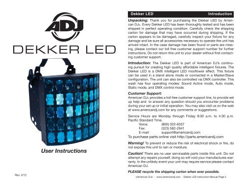
<strong>User</strong> Instructions<br />
<strong>Dekker</strong> <strong>LED</strong><br />
Introduction<br />
Unpacking: Thank you for purchasing the <strong>Dekker</strong> <strong>LED</strong> by <strong>American</strong><br />
<strong>DJ</strong>®. Every <strong>Dekker</strong> <strong>LED</strong> has been thoroughly tested and has been<br />
shipped in perfect operating condition. Carefully check the shipping<br />
carton for damage that may have occurred during shipping. If the<br />
carton appears to be damaged, carefully inspect your fixture for any<br />
damage and be sure all accessories necessary to operate the unit has<br />
arrived intact. In the case damage has been found or parts are missing,<br />
please contact our toll free customer support number for further<br />
instructions. Do not return this unit to your dealer without first contacting<br />
customer support.<br />
Introduction: The <strong>Dekker</strong> <strong>LED</strong> is part of <strong>American</strong> <strong>DJ</strong>’s continuing<br />
pursuit for creating high quality affordable intelligent fixtures. The<br />
<strong>Dekker</strong> <strong>LED</strong> is a DMX intelligent <strong>LED</strong> mooflower effect. This fixture<br />
can be used in a stand alone mode or connected in a Master/Slave<br />
configuration. The unit can also be controlled via DMX controller. This<br />
wash has four operating modes: Sound Active mode, Auto mode,<br />
Static mode, and DMX control mode.<br />
Customer Support:<br />
<strong>American</strong> <strong>DJ</strong>® provides a toll free customer support line, to provide set<br />
up help and to answer any question should you encounter problems<br />
during your set up or initial operation. You may also visit us on the web<br />
at www.americandj.com for any comments or suggestions.<br />
Service Hours are Monday through Friday 8:00 a.m. to 4:30 p.m.<br />
Pacific Standard Time.<br />
Voice: (800) 322-6337<br />
Fax: (323) 582-2941<br />
E-mail: support@americandj.com<br />
To purchase parts online visit http://parts.americandj.com<br />
Warning! To prevent or reduce the risk of electrical shock or fire, do<br />
not expose this unit to rain or moisture.<br />
Caution! There are no user serviceable parts inside this unit. Do not<br />
attempt any repairs yourself, doing so will void your manufactures warranty.<br />
In the unlikely event your unit may require service please contact<br />
<strong>American</strong> <strong>DJ</strong>.<br />
PLEASE recycle the shipping carton when ever possible.<br />
©<strong>American</strong> <strong>DJ</strong>® - www.americandj.com - <strong>Dekker</strong> <strong>LED</strong> Instruction <strong>Manual</strong> Page 2
<strong>Dekker</strong> <strong>LED</strong> General Instructions <strong>Dekker</strong> <strong>LED</strong> Safety Precautions<br />
To optimize the performance of this product, please read these<br />
operating instructions carefully to familiarize yourself with the basic<br />
operations of this unit. These instructions contain important safety<br />
information regarding the use and maintenance of this unit. Please<br />
keep this manual with the unit, for future reference.<br />
<strong>Dekker</strong> <strong>LED</strong><br />
• Q4 <strong>LED</strong> Technology<br />
• Includes Built-In Hanging Yoke<br />
• Sound-Active<br />
• Light Weight<br />
• Strobing<br />
• Electronic Dimming 0-100%<br />
• Built in Microphone<br />
• DMX-512 protocol<br />
• 2 DMX Channel Modes: 2 Channels & 8 Channels<br />
<strong>Dekker</strong> <strong>LED</strong><br />
Features<br />
Warranty Registration<br />
The <strong>Dekker</strong> <strong>LED</strong> carries a three year (1095 days) limited warranty.<br />
Please fill out the enclosed warranty card to validate your purchase.<br />
All returned service items whether under warranty or not, must be<br />
freight pre-paid and accompany a return authorization (R.A.) number.<br />
The R.A. number must be clearly written on the outside of the<br />
return package. A brief description of the problem as well as the R.A.<br />
number must also be written down on a piece of paper and included<br />
in the shipping container. If the unit is under warranty, you must provide<br />
a copy of your proof of purchase invoice. You may obtain a R.A.<br />
number by contacting customer support at (800) 322-6337.<br />
• To reduce the risk of electrical shock or fire, do not expose this unit<br />
rain or moisture<br />
• Do not spill water or other liquids into or on to your unit.<br />
• Be sure that the local power outlet match that of the required voltage<br />
for your unit.<br />
• Do not attempt to operate this unit if the power cord has been<br />
frayed or broken. Do not attempt to remove or break off the ground<br />
prong from the electrical cord. This prong is used to reduce the risk<br />
of electrical shock and fire in case of an internal short.<br />
• Disconnect from main power before making any type of connection.<br />
• Do not remove the cover under any conditions. There are no user<br />
serviceable parts inside.<br />
• Never operate this unit when it’s cover is removed.<br />
• Never plug this unit in to a dimmer pack<br />
• Always be sure to mount this unit in an area that will allow proper<br />
ventilation. Allow about 6” (15cm) between this device and a wall.<br />
• Do not attempt to operate this unit, if it becomes damaged.<br />
• This unit is intended for indoor use only, use of this product out`<br />
doors voids all warranties.<br />
• During long periods of non-use, disconnect the unit’s main power.<br />
• Always mount this unit in safe and stable matter.<br />
• Power-supply cords should be routed so that they are not likely to<br />
be walked on or pinched by items placed upon or against them,<br />
paying particular attention to the point they exit from the unit.<br />
• Cleaning -The fixture should be cleaned only as recommended by<br />
t he manufacturer. See page 12 for cleaning details.<br />
• Heat -The appliance should be situated away from heat sources<br />
such as radiators, heat registers, stoves, or other appliances (includ<br />
ing amplifiers) that produce heat.<br />
• The fixture should be serviced by qualified service personnel<br />
when:<br />
A. The power-supply cord or the plug has been damaged.<br />
B. Objects have fallen, or liquid has been spilled into the appliance.<br />
C. The appliance has been exposed to rain or water.<br />
D. The appliance does not appear to operate normally or exhibits a<br />
marked change in performance.<br />
©<strong>American</strong> <strong>DJ</strong>® - www.americandj.com - <strong>Dekker</strong> <strong>LED</strong> Instruction <strong>Manual</strong> Page 3 ©<strong>American</strong> <strong>DJ</strong>® - www.americandj.com - <strong>Dekker</strong> <strong>LED</strong> Instruction <strong>Manual</strong> Page 4
POWER<br />
POWER<br />
<strong>Dekker</strong> <strong>LED</strong><br />
Set Up<br />
Power Supply: The <strong>American</strong> <strong>DJ</strong>® <strong>Dekker</strong> <strong>LED</strong> contains a automatic<br />
voltage switch, which will auto sense the voltage when it is plugged<br />
into the power source. With this switch there is no need to worry about<br />
the correct power voltage, this unit can be plugged in anywhere.<br />
DMX-512: DMX is short for Digital Multiplex. This is a universal protocol<br />
used as a form of communication between intelligent fixtures<br />
and controllers. A DMX controller sends DMX data instructions from<br />
the controller to the fixture. DMX data is sent as serial data that travels<br />
from fixture to fixture via the DATA “IN” and DATA INPUT “OUT” XLR ter-<br />
REMOTE INPUT OUTPUT<br />
SOUND<br />
CONTROL<br />
SOUND<br />
minals located on all DMX fixtures (most controllers only have a DATA<br />
“OUT” terminal).<br />
DMX Linking: DMX is a language allowing all makes and models of<br />
different manufactures to be linked together and operate from a single<br />
controller, as long as all fixtures and the controller are DMX compliant.<br />
To ensure proper DMX data transmission, when using several<br />
POWER<br />
DMX fixtures try to use the shortest cable path possible. The order<br />
DMX512<br />
in which fixtures are connected in a DMX line DMX+,DMX-,COMMON<br />
does not influence the<br />
DMX addressing. For example; a fixture assigned a DMX address of 1<br />
may be placed anywhere in a DMX line, at the beginning, at the end,<br />
or anywhere in the middle. When a fixture is assigned a DMX address<br />
of 1, the DMX controller knows to send DATA assigned to address 1<br />
to that unit, no matter where it is located in the DMX chain.<br />
1<br />
Data Cable (DMX Cable) Requirements<br />
DMX512<br />
(For<br />
OUT<br />
DMX +<br />
DMX 3Operation):<br />
3-PIN XLR 2<br />
DMX -<br />
The <strong>Dekker</strong> <strong>LED</strong> can be a 2 channel DMX unit or 8 channel DMX unit.<br />
The DMX address is set electronically using the controls on the rear<br />
panel of the unit. Your unit and your DMX controller require a approved<br />
DMX-512 110 Ohm Data cable for data input and data output. We recommend<br />
Accu-Cable DMX cables. If you are making your own cables,<br />
be sure to use standard 110-120 Ohm shielded<br />
cable (This cable may be purchased at almost<br />
all professional sound and lighting stores). Your<br />
cables should be made with a male and female<br />
XLR connector on either end of the cable. Also<br />
remember that DMX cable must be daisy chained<br />
and cannot be split.<br />
Figure 1<br />
©<strong>American</strong> <strong>DJ</strong>® - www.americandj.com - <strong>Dekker</strong> <strong>LED</strong> Instruction <strong>Manual</strong> Page 5<br />
COMMON<br />
3<br />
1<br />
2<br />
<strong>Dekker</strong> <strong>LED</strong><br />
DMX512<br />
Set Up<br />
DMX+,DMX-,COMMON<br />
Notice: Be sure to follow figures two and three when making your own<br />
cables. Do not use the ground lug on the XLR connector. Do not connect<br />
the cable’s shield conductor to the ground lug or allow the shield<br />
conductor to come in contact with the XLR’s outer casing. Grounding<br />
the shield could cause a short circuit and erratic behavior.<br />
XLR INPUT Male Socket<br />
1 Ground<br />
Figure 3<br />
DMX512 OUT<br />
3-PIN XLR<br />
2 Cold 2 Cold<br />
3 Hot<br />
1<br />
2<br />
3<br />
COMMON<br />
DMX +<br />
DMX -<br />
XLR Female Socket<br />
DMX512 IN<br />
3-PIN XLR<br />
©<strong>American</strong> <strong>DJ</strong>® - www.americandj.com - <strong>Dekker</strong> <strong>LED</strong> Instruction <strong>Manual</strong> Page 6<br />
3<br />
1 Ground<br />
3 Hot<br />
1<br />
2<br />
Figure 2<br />
INPUT<br />
XLR Pin Configuration<br />
Pin 1 = Ground<br />
Pin 2 = Data Compliment (negative)<br />
Pin 3 = Data True (positive)<br />
Special Note: Line Termination. When longer runs of cable are<br />
used, you may need to use a terminator on the last unit to avoid erratic<br />
behavior. A terminator is a 110-120 ohm 1/4 watt resistor which is connected<br />
between pins 2 and 3 of a male XLR connector (DATA + and<br />
DATA -). This unit is inserted in the female XLR connector of the last<br />
unit in your daisy chain to terminate the line. Using a cable terminator<br />
(A<strong>DJ</strong> part number Z-DMX/T) will decrease the possibilities of erratic<br />
behavior.<br />
DMX512 IN<br />
3-PIN XLR<br />
REMOTE<br />
CONTROL<br />
INPUT<br />
OUTPUT<br />
POWER<br />
3<br />
1<br />
2<br />
SOUND<br />
Termination reduces signal errors and<br />
avoids signal transmission problems<br />
and interference. It is always advisable<br />
to connect a DMX terminal, (Resistance<br />
120 Ohm 1/4 W) between PIN 2 (DMX-)<br />
and PIN 3 (DMX +) of the last fixture.<br />
REMOTE<br />
CONTROL<br />
INPUT<br />
OUTPUT<br />
Figure 4<br />
5-Pin XLR DMX Connectors. Some manufactures use 5-pin DMX-<br />
512 data cables for DATA transmission in place of 3-pin. 5-pin DMX<br />
fixtures may be implemented in a 3-pin DMX line. When inserting standard<br />
5-pin data cables in to a 3-pin line a cable adaptor must be used,<br />
these adaptors are readily available at most electric stores. The chart<br />
below details a proper cable conversion.<br />
Conductor<br />
Ground/Shield<br />
Data Compliment (- signal)<br />
Data True (+ signal)<br />
Not Used<br />
Not Used<br />
3-Pin XLR to 5-Pin XLR Conversion<br />
3-Pin XLR Female (Out)<br />
Pin 1<br />
Pin 2<br />
Pin 3<br />
POWER<br />
5-Pin XLR Male (In)<br />
Pin 1<br />
Pin 2<br />
Pin 3<br />
Do Not Use<br />
Do Not Use<br />
3<br />
1<br />
2<br />
Termination redu<br />
avoids signal tra<br />
and interference.<br />
to connect a DMX<br />
120 Ohm 1/4 W)<br />
and PIN 3 (DMX
<strong>Dekker</strong> <strong>LED</strong><br />
Operating Instructions<br />
<strong>LED</strong> Display On/Off:<br />
To set the <strong>LED</strong> display to turn off after 10 seconds, press the MODE<br />
button until 0001 is displayed, press the UP button to display 0002.<br />
Now the display will disappear after 10s. Press any button for at least<br />
10s to turn the display on again. Be advised though that the display<br />
will turn off automatically after 10 seconds.<br />
To set the display press the MODE button until 0001 is displayed.<br />
The display will now stay on at all times.<br />
ds-1= LCD display on at all times.<br />
ds-2= LCD display shuts off after 10 seconds.<br />
Master-Slave Operation:<br />
This function will allows you to link units together to run in a Master-<br />
Slave mode. In Master-Slave operation one unit will act as the controlling<br />
unit and the others will react to the controlling units built-in<br />
programs. Any unit can act as a Master or as a Slave however, only<br />
one unit can be programmed to act as the “Master.”<br />
Master-Slave Connections and Settings:<br />
1. Daisy chain your units via the XLR connector on the rear of<br />
the unit. Use standard XLR microphone cables to link your<br />
units together. Remember that the Male XLR connector is the<br />
input and the Female XLR connector is the output. The first<br />
unit in the chain (master) will use the female XLR connector<br />
only. The last unit in the chain will use the male XLR<br />
connector only.<br />
2. You will also have to link the power cords to each other, as you<br />
did with the XLR cables.<br />
3. Choose your Master unit, and press the MODE button until “5-<br />
XX” is displayed. You are now in Master mode and you can use<br />
the UP or DOWN buttons to select your desired show from 0-20<br />
or Sound Active (5-So)<br />
4. With the “Slave” unit(s) press the MODE button until “4-XX” is<br />
displayed. They will now follow the “Master” unit.<br />
Dance Mode:<br />
There are two dance programs to choose from, fast dance and slow<br />
dance.<br />
1. Plug the fixture in and press the MODE button until“1--X” is<br />
<strong>Dekker</strong> <strong>LED</strong><br />
Operating Instructions<br />
displayed. “X” represents the current number being displayed.<br />
2. Select your desired dance program by pressing either the<br />
UP or DOWN buttons.<br />
3. 1--1 is a fast dance program. 1--2 is a slow dance program.<br />
DMX Mode:<br />
The <strong>Dekker</strong> <strong>LED</strong> has 2 DMX Channel modes. You can choose between<br />
2 DMX channels or 8 DMX Channels. Operating through a<br />
DMX controller give the user the freedom to create their own programs<br />
tailored to their own individual needs.<br />
1. This function will allow you to control each individual fixture’s<br />
traits with a standard DMX 512 controller such as the<br />
Elation® Show Designer or the Elation® DMX Operator.<br />
2. To run your fixture in DMX mode, plug in the fixture via the XLR<br />
connections to any standard DMX controller.<br />
3. Choose your DMX channel mode -<br />
Press the MODE button until “2XXX” is displayed, this is 2 channel<br />
mode. Press the UP or DOWN button to find your desired<br />
DMX address.<br />
Press the MODE button until “3XXX” is displayed, this is 8 channel<br />
mode. Press the UP or DOWN button to find your desired<br />
DMX address.<br />
4. Please see pages 10-11 for DMX values and traits.<br />
Adjustment Mode:<br />
1. Plug the fixture in and press the MODE button until“6-XX” is<br />
displayed.<br />
2. Select your desired program in mode 6 by pressing either the<br />
UP or DOWN buttons. There are 10 programs to choose from.<br />
3. Adjust the program speed by pressing the MODE button until<br />
“7-XX” is displayed. Press either the UP or DOWN buttons to adjust<br />
the speed of the program. When “7-so” is displayed the program<br />
is running in sound active mode.<br />
UC3 F Mode:<br />
Choose a color to remain static.<br />
1. Plug the fixture in and press the MODE button until “UC3 F” is<br />
displayed.<br />
©<strong>American</strong> <strong>DJ</strong>® - www.americandj.com - <strong>Dekker</strong> <strong>LED</strong> Instruction <strong>Manual</strong> Page 7 ©<strong>American</strong> <strong>DJ</strong>® - www.americandj.com - <strong>Dekker</strong> <strong>LED</strong> Instruction <strong>Manual</strong> Page 8
<strong>Dekker</strong> <strong>LED</strong><br />
Operating Instructions<br />
2. Now you can use the UC3 Controller (Not Included) to control various<br />
functions. See below for UC3 controls.<br />
Button<br />
STAND BY<br />
FUNCT I ON<br />
ST R OBE<br />
Function<br />
Open or close screen when pressing this button<br />
1 R<br />
2 G<br />
3 B<br />
4 W<br />
5 RGBW<br />
6 Auto Mix-color<br />
7 Sound Mode<br />
Open or close strobe mode when pressing this button<br />
<strong>Dekker</strong> <strong>LED</strong> 2 Channel Mode - DMX Values & Traits<br />
Channel Value Function<br />
1 PROGRAMS<br />
1 - 26 4 COLOR FADE CHANGE<br />
27 - 51 9 COLOR FADE CHANGE<br />
52 - 76 4 COLOR LOOP CHANGE<br />
77 - 101 9 COLOR LOOP CHANGE<br />
102 - 126 STROBE 1 DIM - BRIGHT<br />
127 - 151 STROBE 2 BRIGHT - DIM<br />
152 - 176 STROBE 3 DIM - BRIGHT - DIM<br />
177 - 201 STROBE 4 W/O DIM EFFECT<br />
202 - 226 STROBE 5 WITH 9 COLOR<br />
227 - 254 STROBE 6 WITH GRADUAL DIM<br />
255 ALL PROGRAMS WILL CYCLE<br />
2 PROGRAM SPEED<br />
1 - 254 SLOW - FAST<br />
255 SOUND ACTIVE<br />
©<strong>American</strong> <strong>DJ</strong>® - www.americandj.com - <strong>Dekker</strong> <strong>LED</strong> Instruction <strong>Manual</strong> Page 9<br />
©<strong>American</strong> <strong>DJ</strong>® - www.americandj.com - <strong>Dekker</strong> <strong>LED</strong> Instruction <strong>Manual</strong> Page 10
<strong>Dekker</strong> <strong>LED</strong> 8 Channel Mode - DMX Values & Traits<br />
Channel Value Function<br />
1 MOTOR FUNCTION CONTROL<br />
1 - 127 ROTATE CLOCKWISE SLOW - FAST<br />
128 - 255 ROTATE COUNTER CLOCKWISE<br />
FAST - SLOW<br />
2 RED INTENSITY<br />
1 - 255 0% - 100%<br />
3 GREEN INTENSITY<br />
1 - 255 0% - 100%<br />
4 BLUE INTENSITY<br />
1 - 255 0% - 100%<br />
5 WHITE INTENSITY<br />
1 - 255 0% - 100%<br />
6 MASTER INTENSITY CONTROL<br />
0% - 100%<br />
7 PROGRAMS<br />
1 - 26 4 COLOR LOOP CHANGE<br />
27 - 51 9 COLOR FADE CHANGE<br />
52 - 76 4 COLOR LOOP CHANGE<br />
77 - 101 9 COLOR LOOP CHANGE<br />
102 - 126 STROBE 1 DIM - BRIGHT<br />
127 - 151 STROBE 2 BRIGHT - DIM<br />
152 - 176 STROBE 3 DIM - BRIGHT - DIM<br />
177 - 201 STROBE 4 W/O DIM EFFECT<br />
202 - 226 STROBE 5 WITH 9 COLOR<br />
227 - 254 STROBE 6 WITH GRADUAL DIM<br />
255 ALL PROGRAMS WILL CYCLE<br />
8 PROGRAM SPEED<br />
1 - 254 SLOW - FAST<br />
255 SOUND ACTIVE<br />
NOTE: Regarding Channel 7, <strong>LED</strong> intensity is controlled by<br />
Channels 2 - 5. Channel 7 <strong>LED</strong> program speed is controlled<br />
by Channel 8.<br />
<strong>Dekker</strong> <strong>LED</strong><br />
<strong>Dekker</strong> <strong>LED</strong><br />
Trouble Shooting<br />
Trouble Shooting: Listed below are a few common problems that<br />
you may encounter, with solutions.<br />
No light output from the unit;<br />
1. Be sure you have connected your unit into a standard 110V wall<br />
outlet.<br />
2. Be sure the fuse has not blown. The fuse is located on the rear<br />
panel.<br />
Unit does not respond to sound;<br />
1. Low frequencies (bass) should cause the unit to react to sound.<br />
Tapping on the microphone, quiet or high pitched sounds may not<br />
activate the unit.<br />
<strong>Dekker</strong> <strong>LED</strong><br />
Fuse Replacement<br />
Fuse Replacement: First unplug the power. The fuse holder is located<br />
at the rear of the unit next to the power cord. Using a flat-head<br />
screw driver unscrew the fuse holder. Remove the bad fuse and replace<br />
with a new one.<br />
Cleaning<br />
Fixture Cleaning: Due to fog residue, smoke, and dust cleaning the<br />
internal and external optical lenses must be carried out periodically to<br />
optimize light output.<br />
1. Use normal glass cleaner and a soft cloth to wipe down the<br />
outside casing.<br />
2. Use a brush to wipe down the fan grill.<br />
3. Clean the external optics with glass cleaner and a soft cloth every<br />
20 days.<br />
4. Clean the internal optics with glass cleaner and a soft cloth<br />
every 30-60 days.<br />
5. Always be sure to dry all parts completely before plugging<br />
the unit back in.<br />
Cleaning frequency depends on the environment in which the fixture<br />
operates (I.e. smoke, fog residue, dust, dew). In heavy club use we<br />
recommend cleaning on a monthly basis. Periodic cleaning will ensure<br />
longevity, and crisp output.<br />
©<strong>American</strong> <strong>DJ</strong>® - www.americandj.com - <strong>Dekker</strong> <strong>LED</strong> Instruction <strong>Manual</strong> Page 11<br />
©<strong>American</strong> <strong>DJ</strong>® - www.americandj.com - <strong>Dekker</strong> <strong>LED</strong> Instruction <strong>Manual</strong> Page 12
<strong>Dekker</strong> <strong>LED</strong><br />
Warranty<br />
MANUFACTURER’S LIMITED WARRANTY<br />
A. <strong>American</strong> <strong>DJ</strong>, Inc. hereby warrants, to the original purchaser, <strong>American</strong> <strong>DJ</strong> and <strong>American</strong><br />
Audio products to be free of manufacturing defects in material and workmanship for a prescribed<br />
period from the date of purchase (see specific warranty period on reverse). This warranty shall be<br />
valid only if the product is purchased within the United States of America, including possessions<br />
and territories. It is the owner’s responsibility to establish the date and place of purchase by acceptable<br />
evidence, at the time service is sought.<br />
B. For warranty service you must obtain a Return Authorization number (RA#) before<br />
sending back the product. Contact <strong>American</strong> <strong>DJ</strong>, Inc. Service Department at 800-322-6337. Send<br />
the product only to the <strong>American</strong> <strong>DJ</strong>, Inc. factory. All shipping charges must be pre-paid. If the<br />
requested repairs or service (including parts replacement) are within the terms of this warranty,<br />
<strong>American</strong> <strong>DJ</strong>, Inc. will pay return shipping charges only to a designated point within the United<br />
States. If the entire instrument is sent, it must be shipped in it’s original package. No accessories<br />
should be shipped with the product. If any accessories are shipped with the product, <strong>American</strong> <strong>DJ</strong>,<br />
Inc. shall have no liability whatsoever for loss of or damage to any such accessories, nor for the<br />
safe return thereof.<br />
C. This warranty is void if the serial number has been altered or removed; if the product is<br />
modified in any manner which <strong>American</strong> <strong>DJ</strong>, Inc. concludes, after inspection, affects the reliability<br />
of the product; if the product has been repaired or serviced by anyone other than the <strong>American</strong> <strong>DJ</strong>,<br />
Inc. factory unless prior written authorization was issued to purchaser by <strong>American</strong> <strong>DJ</strong>, Inc.; if the<br />
product is damaged because not properly maintained as set forth in the instruction manual.<br />
D. This is not a service contract, and this warranty does not include maintenance, cleaning<br />
or periodic check-up. During the period specified above, <strong>American</strong> <strong>DJ</strong>, Inc. will replace defective<br />
parts at its expense with new or refurbished parts, and will absorb all expenses for warranty<br />
service and repair labor by reason of defects in material or workmanship. The sole responsibility<br />
of <strong>American</strong> <strong>DJ</strong>, Inc. under this warranty shall be limited to the repair of the product, or replacement<br />
thereof, including parts, at the sole discretion of <strong>American</strong> <strong>DJ</strong>. All products covered by this<br />
warranty were manufactured after January 1, 1990, and bear identifying marks to that effect.<br />
E. <strong>American</strong> <strong>DJ</strong>, Inc. reserves the right to make changes in design and/or improvements<br />
upon its products without any obligation to include these changes in any products theretofore<br />
manufactured. No warranty, whether expressed or implied, is given or made with respect to any<br />
accessory supplied with products described above. Except to the extent prohibited by applicable<br />
law, all implied warranties made by <strong>American</strong> <strong>DJ</strong>, Inc. in connection with this product, including<br />
warranties of merchantability or fitness, are limited in duration to the warranty period set forth<br />
above. And no warranties, whether expressed or implied, including warranties of merchantability<br />
or fitness, shall apply to this product after said period has expired. The consumer’s and/or Dealer’s<br />
sole remedy shall be such repair or replacement as is expressly provided above; and under no<br />
circumstances shall <strong>American</strong> <strong>DJ</strong>, Inc. be liable for any loss or damage, direct or consequential,<br />
arising out of the use of, or inability to use, this product.<br />
This warranty is the only written warranty applicable to <strong>American</strong> <strong>DJ</strong> and <strong>American</strong> Audio<br />
Products and supersedes all prior warranties and written descriptions of warranty terms and<br />
conditions heretofore published.<br />
MANUFACTURER’S LIMITED WARRANTY PERIODS:<br />
• All <strong>American</strong> Audio Products = 1-year (365 day) Limited Warranty (except V-Plus Series Amplifiers)<br />
• All <strong>American</strong> Audio V-Plus Series Amplifiers = 3-year (1095 day) Limited Warranty<br />
• <strong>American</strong> <strong>DJ</strong> Lighting and <strong>American</strong> <strong>DJ</strong> Branded Products = 1-year (365 day) Limited Warranty<br />
(Such as: Special Effect Lighting, Intelligent Lighting, UV lighting, Strobes, Fog Machines, Bubble<br />
Machines, Mirror Balls, Par Cans, Trussing, Lighting Stands etc. excluding Laser Products and<br />
lamps)<br />
• <strong>American</strong> <strong>DJ</strong> Laser Products = 90-Day Limited Warranty<br />
• <strong>American</strong> <strong>DJ</strong> L.E.D. Products = 3-year (1095 day) Limited Warranty (excluding motors which<br />
have a 1-year (365 day Limited Warranty)<br />
©<strong>American</strong> <strong>DJ</strong>® - www.americandj.com - <strong>Dekker</strong> <strong>LED</strong> Instruction <strong>Manual</strong> Page 13<br />
<strong>Dekker</strong> <strong>LED</strong><br />
©<strong>American</strong> <strong>DJ</strong>® - www.americandj.com - <strong>Dekker</strong> <strong>LED</strong> Instruction <strong>Manual</strong> Page 14<br />
Notes
<strong>Dekker</strong> <strong>LED</strong><br />
Technical Specifications:<br />
Model: <strong>Dekker</strong> <strong>LED</strong><br />
<strong>LED</strong>s:<br />
Voltage:<br />
Power Consumption:<br />
Dimensions:<br />
Colors:<br />
Weight:<br />
DMX Channels:<br />
Fuse:<br />
Duty Cycle:<br />
Specifications<br />
2 x 5W RGBW <strong>LED</strong>s<br />
100~240v 50Hz~60Hz<br />
25W<br />
11”(L) x 9.8”(W) x 10.23”(H)<br />
RGB + White<br />
8.5 Lbs./3.85 Kgs.<br />
2 Channel or 8 Channels<br />
1 Amp<br />
None<br />
Please Note: Specifications and improvements in the design of<br />
this unit and this manual are subject to change without any prior<br />
written notice.<br />
Auto Sensing Voltage: This fixture contains a automatic voltage<br />
switch, which will auto sense the voltage when it is plugged into<br />
the power source.<br />
©<strong>American</strong> <strong>DJ</strong>® - www.americandj.com - <strong>Dekker</strong> <strong>LED</strong> Instruction <strong>Manual</strong> Page 15<br />
©<strong>American</strong> <strong>DJ</strong> Supply<br />
<strong>American</strong> <strong>DJ</strong> World Headquarters:<br />
6122 S. Eastern Ave. Los Angeles, CA 90040 USA<br />
Tel: 323-582-2650 / Fax: 323-725-6100<br />
Web: www.americandj.com / E-mail: info@americandj.com<br />
<strong>American</strong> <strong>DJ</strong> Europe<br />
Junostraat 2<br />
6468 EW Kerkrade<br />
Netherlands<br />
service@adjgroup.eu / www.americandj.eu<br />
Tel: +31 45 546 85 00 / Fax: +31 45 546 85 99