IC101G Coro-Vane Stationary Pumps - Corken
IC101G Coro-Vane Stationary Pumps - Corken
IC101G Coro-Vane Stationary Pumps - Corken

Create successful ePaper yourself
Turn your PDF publications into a flip-book with our unique Google optimized e-Paper software.
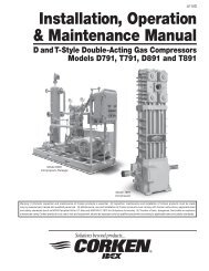
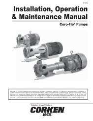
<strong>IC101G</strong><br />
Installation, Operation<br />
& Maintenance Manual<br />
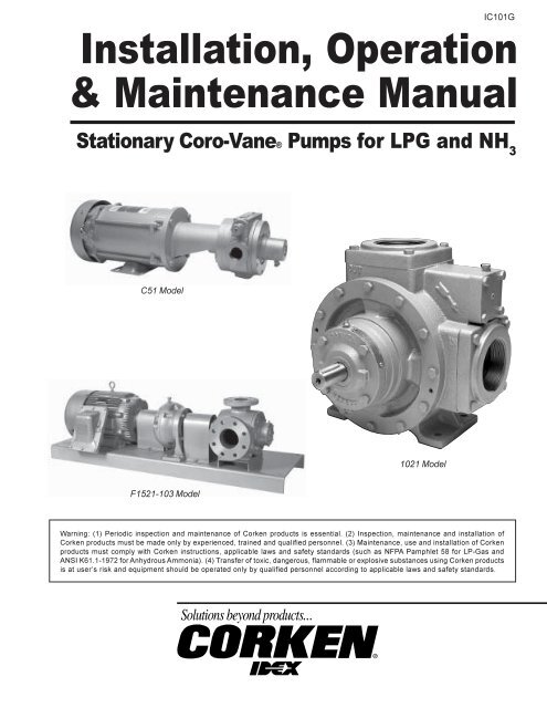
<strong>Stationary</strong> <strong>Coro</strong>-<strong>Vane</strong>® <strong>Pumps</strong> for LPG and NH 3<br />
C51 Model<br />
1021 Model<br />
F1521-103 Model<br />
Warning: (1) Periodic inspection and maintenance of <strong>Corken</strong> products is essential (2) Inspection, maintenance and installation of<br />
<strong>Corken</strong> products must be made only by experienced, trained and qualified personnel (3) Maintenance, use and installation of <strong>Corken</strong><br />
products must comply with <strong>Corken</strong> instructions, applicable laws and safety standards (such as NFPA Pamphlet 58 for LP-Gas and<br />
ANSI K611-1972 for Anhydrous Ammonia) (4) Transfer of toxic, dangerous, flammable or explosive substances using <strong>Corken</strong> products<br />
is at user’s risk and equipment should be operated only by qualified personnel according to applicable laws and safety standards
Warning<br />
Install, use and maintain this equipment according to <strong>Corken</strong>’s instructions and all applicable federal, state, local laws<br />
and codes Periodic inspection and maintenance is essential<br />
<strong>Corken</strong> One Year Limited Warranty<br />
<strong>Corken</strong>, Inc warrants that its products will be free from defects in material and workmanship for a period of 12 months<br />
following date of purchase from <strong>Corken</strong> <strong>Corken</strong> products which fail within the warranty period due to defects in material<br />
or workmanship will be repaired or replaced at <strong>Corken</strong>’s option, when returned, freight prepaid to <strong>Corken</strong>, Inc, 3805<br />
NW 36 th Street, Oklahoma City, Oklahoma 73112<br />
Parts subject to wear or abuse, such as mechanical seals, vanes, piston rings, packing and other parts showing signs of<br />
abuse are not covered by this limited warranty Also, equipment, parts and accessories not manufactured by <strong>Corken</strong> but<br />
furnished with <strong>Corken</strong> products are not covered by this limited warranty and purchaser must look to the original<br />
manufacturer’s warranty, if any This limited warranty is void if the <strong>Corken</strong> product has been altered or repaired without<br />
the consent of <strong>Corken</strong><br />
All implied warranties, including any implied warranty of merchantability or fitness for a particular purpose, are expressly<br />
negated to the extent permitted by law and shall in no event extend beyond the expressed warranty period<br />
<strong>Corken</strong> disclaims any liability for consequential damages due to breach of any written or implied warranty on <strong>Corken</strong><br />
products Transfer of toxic, dangerous, flammable or explosive substances using <strong>Corken</strong> products is at the user’s risk<br />
Such substances should be handled by experienced, trained personnel in compliance with governmental and industrial<br />
safety standards<br />
Important notes relating to the European Union (EU) Machinery Directive<br />
<strong>Pumps</strong> delivered without electric motors are not considered as machines in the EU Machinery Directive These pumps<br />
will be delivered with a Declaration of Incorporation The fabricator of the machinery must assure and declare full compliance<br />
with this Directive before the machine in which the pump will be incorporated, or of which it is a part, is put into service<br />
Contacting the Factory<br />
Before you contact the factory, note the model number and serial number of your pump The serial number directs us to<br />
a file containing all information on material specifications and test data applying to your specific pump When ordering<br />
parts, the <strong>Corken</strong> service manual or Installation, Operations and Maintenance (IOM) manual should be consulted for the<br />
proper part numbers ALWAYS INCLUDE THE MODEL NUMBER AND SERIAL NUMBER WHEN ORDERING PARTS<br />
The model and serial numbers are shown on the nameplate of the unit Record this information for future reference<br />
Model no ______________________________________________________________________________________<br />
Serial no ______________________________________________________________________________________<br />
Date purchased _________________________________________________________________________________<br />
Date installed ___________________________________________________________________________________<br />
Purchased from _________________________________________________________________________________<br />
Installed by _____________________________________________________________________________________<br />
2
Table of Contents<br />
Principles of Your <strong>Coro</strong>-<strong>Vane</strong>® Pump 4<br />
Exclusive Features of Your <strong>Coro</strong>-<strong>Vane</strong>® Pump 4<br />
Installation of Your <strong>Coro</strong>-<strong>Vane</strong>® Pump 4<br />
Inlet Piping 5<br />
Outlet Piping 5<br />
By-Pass System 5<br />
Vapor Equalizing System 5<br />
Driver Installation 5<br />
Operation of Your <strong>Coro</strong>-<strong>Vane</strong>® Pump 6<br />
Piping Diagram 7<br />
Maintenance of Your <strong>Coro</strong>-<strong>Vane</strong>® Pump System 8<br />
Pump Maintenance Schedule 8<br />
Preventative Maintenance Program 9<br />
Seal Replacement Instructions 10<br />
Parts Details For A <strong>Stationary</strong> <strong>Coro</strong>-<strong>Vane</strong>® Seal Assembly 13 and 14<br />
Repair Kits 15<br />
Parts Details For All <strong>Stationary</strong> <strong>Coro</strong>-<strong>Vane</strong>® Models 16–22<br />
Appendix A<br />
Model Number and Identification Code 23 and 24<br />
Appendix B<br />
Operating, Material and Flange Specifications 25 and 26<br />
Appendix C<br />
Performance Curves 27–30<br />
Appendix D<br />
Outline Dimensions 31–36<br />
Appendix E<br />
V-Belt Selection Guide 37<br />
Appendix F<br />
Troubleshooting Guide 38<br />
Appendix G<br />
Storage of Your <strong>Coro</strong>-<strong>Vane</strong>® <strong>Stationary</strong> Pump 39<br />
3
Principles of Your <strong>Coro</strong>-<strong>Vane</strong> ® Pump<br />
The <strong>Corken</strong> <strong>Coro</strong>-<strong>Vane</strong>® pumps are a special type of rotary<br />
positive displacement pump, known as a sliding vane pump<br />
The sliding vane pump has many of the positive displacement<br />
advantages of the gear pump, plus the ability to compensate<br />
for wear, and operate at a lower noise level<br />
The sliding vane pump consists of a rotor turning in a cam<br />
(liner) machined eccentrically in relation to the rotor; thereby<br />
displacing the liquid trapped between the rotor, cam and<br />
vanes The <strong>Corken</strong> <strong>Coro</strong>-<strong>Vane</strong>® pumps are made with vanes<br />
produced from advanced polymers which exhibit extremely<br />
low coefficients of friction The vanes are self-adjusting for<br />
wear which gives the pump long life<br />
Exclusive Features of Your<br />
<strong>Coro</strong>-<strong>Vane</strong> ® Pump<br />
The pumping of volatile liquids is one of the most difficult of<br />
all pumping jobs, so more attention must be given to the<br />
design and manufacture of the pump and to its installation<br />
and operation<br />
In addition to being especially suited for handling volatile<br />
liquids, your <strong>Coro</strong>-<strong>Vane</strong>® pump has a number of features<br />
to help make it more easily operated and maintained<br />
The <strong>Coro</strong>-<strong>Vane</strong>® pump is manufactured in six models: the<br />
Models C51 and F51 small stationary and the Models 521,<br />
1021, F1021 and F1521 stationary pumps The Models<br />
F1021 and F1521 have ANSI flanged connections All six<br />
models have been registered and listed by the<br />
UNDERWRITERS' LABORATORIES, INC for use in the<br />
handling of LP-Gas and Ammonia<br />
The CASE AND HEADS are made of ductile iron for extra<br />
strength and toughness<br />
The VANES are manufactured of advanced polymers to<br />
provide excellent life and quiet operation After long service,<br />
the vanes are simply and inexpensively replaced<br />
Both the CAM and the SIDEPLATES are easily replaced<br />
should the need arise<br />
The MECHANICAL SEAL is designed for longer life under<br />
greater loads and may be inspected or replaced without<br />
disturbing the piping of the pump No special tools are needed<br />
BEARINGS are heavy-duty roller type for long bearing life<br />
PRESSURE GAUGE connections, 1/4" pipe thread, are provided<br />
The PUMP NOZZLES on Models 521 and 1021 are<br />
equipped with flanges to simplify piping It is not necessary<br />
to provide unions in the piping system near the pump<br />
because the flanges serve this purpose<br />
The RELIEF VALVE is built-in as part of the pump on models<br />
521 and 1021 and is adjustable under pressure<br />
NOTE: EVEN WITH THIS INTERNAL SAFETY VALVE, AN<br />
EXTERNAL BY-PASS VALVE MUST BE INSTALLED<br />
Installation of Your <strong>Corken</strong><br />
<strong>Coro</strong>-<strong>Vane</strong> ® Pump<br />
The installation of the <strong>Coro</strong>-<strong>Vane</strong> ® pump is simple However,<br />
in order for the pump to deliver optimum performance, the<br />
principles discussed in this book should be followed The<br />
piping details are furnished to illustrate methods proved by<br />
hundreds of installations Your own needs may require slight<br />
variations, but every effort should be made to follow the<br />
recommendations identified in this manual<br />
No pump can discharge more liquid than it receives, so the<br />
pump location and the inlet piping must be given careful<br />
attention If the inlet piping is inadequate to supply the<br />
demand of the pump, you may expect trouble The inlet<br />
sizes shown in figure 2, page 7, are the smallest size piping<br />
you can use with success<br />
For the transfer of flammable liquids like LPG, the pump<br />
must be installed according to the applicable local safety<br />
and health regulations The installer and/or the user must<br />
take into account the following:<br />
• The pump must be located as near the storage tank as<br />
possible The complete inlet line, including the vertical line<br />
from the tank must not exceed twelve feet (37 m) in length<br />
• The bottom of the tank must be no less than two feet (06<br />
m) above the pump inlet nozzle, with four feet (12m)<br />
considered standard<br />
• The foundation for the pump is important The foundation<br />
must be firm, level and preferably made of concrete The<br />
suggestions in figure 1 should be observed<br />
Figure 1<br />
• Potential risk due to local conditions regarding the<br />
installation and operation (eg poor ventilation and<br />
additional risks due to other elements in the vicinity, etc)<br />
• Qualification of the personnel<br />
• Type of liquid being transferred<br />
4
• Specific safety measures to be applied (eg gas<br />
detection, automatic shut-off valves, personal protective<br />
equipment, etc)<br />
The following table shows the weight of the bare pump<br />
for each model For handling a bare pump, lifting slings<br />
should be used Web slings are preferred over metal<br />
slings to minimize damage to the paint See Appendix D<br />
for outline dimensions<br />
The Inlet Piping Should Include the Following:<br />
1 The tank excess flow valve (EFV) should have a flow<br />
rate of 1-1/2 to 2 times the capacity of he pump Do not<br />
use an EFV without knowing its flow capacity<br />
2<br />
3<br />
4<br />
5<br />
6<br />
The tank shut-off valve must be a free-flow type and<br />
not a standard globe valve<br />
A strainer of the “Y” type, with 30 to 40 mesh screen,<br />
must be on the inlet line of the pump (Mesh size<br />
indicates the number of openings per lineal inch)<br />
Use a flexible connection in the pump inlet and outlet<br />
piping to compensate for piping strains<br />
Use an eccentric swage at the pump inlet nozzle to<br />
change the line size (flat side up)<br />
Make the inlet line level or slope it downward to<br />
the pump<br />
7 The minium inlet piping sizes shown in figure 2, page 7,<br />
must be observed<br />
The Outlet Piping Should Include the Following:<br />
1 A pressure gauge should be installed in the pump outlet<br />
or near it A pressure gauge is necessary to determine<br />
the efficiency of your pumping system<br />
2<br />
3<br />
4<br />
Shipping Weight<br />
Model lb kg<br />
C51 50 227<br />
F51 25 113<br />
521 132 599<br />
1021 200 907<br />
F1021 200 907<br />
F1521 235 1066<br />
A hydrostatic relief valve is required by most state laws<br />
and for your own safety<br />
If the outlet piping exceeds 50 feet (152 m) in length a<br />
check valve should be installed near the pump outlet<br />
The minimum outlet piping sizes shown in figure 2, page<br />
7 should be observed<br />
The By-Pass System Must Include the Following:<br />
1 A pump by-pass system must be installed If the pump<br />
discharge is shut off before the driver is stopped,<br />
2<br />
3<br />
dangerously high pressures can develop, unless a bypass<br />
valve is installed to permit the pump to discharge<br />
back to the supply tank, at a predetermined pressure<br />
The pump may have an internal relief valve, but it is<br />
intended as a safety relief valve device and not an<br />
operational by-pass<br />
Always install an external by-pass relief valve (such as<br />
the <strong>Corken</strong> B177) in the pump discharge line The bypass<br />
valve may discharge into the tank at any convenient<br />
opening, either liquid or vapor; however, it should not<br />
connect into the pump inlet piping system<br />
Pump Model<br />
Max Differential Pressure<br />
521, 1021, F1021 125 psi (88 kg/cm 2 )<br />
F1521 100 psi (70 kg/cm 2 )<br />
A Vapor Equalizing System Should be Included:<br />
To obtain maximum performance from your <strong>Coro</strong>-<strong>Vane</strong>® pump,<br />
a vapor equalizing system should be installed This system is<br />
simply a pipe connecting the vapor sections of the tank being<br />
unloaded and the tank being filled This equalizing line allows<br />
vapor to move freely between the two tanks (in either direction)<br />
and assures that both tanks remain at the same pressure<br />
As liquid is withdrawn from a tank, it must be replaced by an<br />
equal amount of vapor or the pressure in the tank will drop If<br />
an equalizing line is not present, this vapor is formed by<br />
“boiling” of the liquid and a reduction of the tank’s pressure<br />
Meanwhile, the tank being filled experiences a pressure<br />
increase as the rising fluid levels compresses the vapor space<br />
above it A vapor equalizing line will eliminate both of these<br />
problems and will reduce pumping time, differential pressure,<br />
noise and wear on the entire system Slow transfer rates will<br />
minimize these effects, and reduce the need for a vapor<br />
equalizing line However, today’s high transfer rates require<br />
that a vapor equalizing line be installed<br />
Another way to consider this principle is to remember that it<br />
takes two holes in an oil can for oil to be poured smoothly<br />
from the can; one for the oil to exit and the other for the air<br />
to enter The piping and hose sizes shown in figure 2, page<br />
7 should be considered minimum<br />
Driver Installation<br />
Pump Model<br />
Maximum Speed<br />
521, 1021, F1021 950 RPM<br />
F1521<br />
860 RPM<br />
The wiring of your electric motor is extremely important and<br />
must be done by a competent electrical contractor The<br />
following wire sizing chart indicates the minimum standards<br />
for wire sizes<br />
5
Motor Recommended<br />
Approximate wire size, AWG 1<br />
Motor full load Length of run (ft)<br />
Hp phase Volts amperes 0–100 to 200 to 300<br />
3 1 115 340 6 4 2<br />
220 170 12 8 8<br />
3 230 96 12 12 12<br />
460 48 12 12 12<br />
5 1 115 560 4 1 1/0<br />
230 280 10 6 4<br />
3 230 152 12 12 10<br />
460 76 12 12 12<br />
7-1/2 1 230 400 8 6 4<br />
3 230 220 10 10 8<br />
450 110 12 12 12<br />
10 3 230 280 8 8 8<br />
460 140 12 12 12<br />
15 3 230 420 6 6 6<br />
460 210 10 10 10<br />
20 3 230 540 4 4 4<br />
460 270 8 8 8<br />
25 3 230 680 2 2 2<br />
460 340 6 6 6<br />
30 3 230 800 1 1 1<br />
460 400 6 6 6<br />
40 3 230 1000 2/0 2/0 2/0<br />
460 520 4 4 4<br />
50 3 230 1300 3/0 3/0 3/0<br />
460 650 2 2 2<br />
1<br />
Based upon 3% voltage loss copper wire type TW Single phase motor<br />
calculations are based on two times distance<br />
Improper motor wiring will cause expensive motor difficulties<br />
from low voltage If you suspect you have low voltage, call<br />
your power company Connecting your motor for the voltage<br />
you have available is important too The motors furnished<br />
with the stationary pumps are usually dual voltage, so you<br />
must be sure of the voltage your power company is<br />
supplying you Your motor will be completely ruined if it is<br />
connected to the wrong voltage<br />
A humid climate can cause problems, particularly in<br />
explosion proof motor applications The normal breathing<br />
of the motor, and alternating between being warm when<br />
running and cool when stopped, often will cause moist air<br />
to be drawn into the motor housing This moist air will<br />
condense, and may eventually add enough free water to<br />
the inside of the motor to cause it to fail To prevent this,<br />
make a practice of running the motor and pump at least<br />
once a week on a bright, dry day for an hour or so (pumping<br />
through the by-pass system) In this period the motor will<br />
heat up and vaporize the condensed moisture, and drive it<br />
out of the motor No motor manufacturer will guarantee an<br />
explosion-proof or totally enclosed motor against damage<br />
from moisture<br />
Engine drivers pose a special consideration The<br />
manufacturer’s instructions must be followed When the<br />
stationary pump is equipped with an engine from the factory,<br />
the engine speed should normally not exceed 1,800 RPM<br />
Excessive engine speed will overload the engine and cause<br />
early failure The engine loses 3% of its power for every<br />
1,000 feet (305 m) above sea level, so if your installation is<br />
at a higher altitude than normal, consult the factory<br />
Operation of Your <strong>Coro</strong>-<strong>Vane</strong> ® Pump<br />
Performance curves and charts are provided in Appendix C<br />
The following steps should be performed for the initial<br />
pumping operation:<br />
1<br />
2<br />
3<br />
4<br />
5<br />
6<br />
7<br />
8<br />
9<br />
Verify the strainer screen is clean<br />
Rotate the pump by hand<br />
Check V-belt drive or direct drive coupling alignment<br />
Misalignment will cause accelerated wear of the drive<br />
system, motor bearings and pump<br />
Check motor for proper wiring<br />
Review complete system to make certain the function<br />
of every valve and piece of equipment is clearly<br />
understood Everyone operating this system must be<br />
properly trained in normal operating procedures and<br />
emergency procedures in event of a malfunction<br />
Close all hose valves<br />
Slowly open the storage tank bottom shut-off valve<br />
(suction line to the pump) Immediately check the<br />
system for leaks<br />
Open any shut-off valves between the by-pass valve<br />
and the storage tank<br />
Make a note of all pressure gauge readings, especially<br />
the pressure gauge located at the discharge of the<br />
pump Start the pump and circulate the liquid through<br />
the by-pass system back to the storage tank<br />
10 Verify the proper pump rotation direction There is an<br />
arrow cast in the pump case<br />
11 An ammeter may be used by adjusting the by-pass<br />
valve until the ammeter indicates the full load motor<br />
amperage rating shown on the motor nameplate or<br />
maximum rated differential, whichever comes first<br />
Permit the pump to circulate liquid for half an hour or<br />
more If the motor overload protection device stops the<br />
motor in this period the by-pass valve setting is too<br />
high and should be readjusted until the motor will run<br />
for half an hour After a satisfactory setting is achieved,<br />
“seal” the valve adjusting stem to prevent tampering<br />
with the adjustment See IH102 for more details on the<br />
use of the <strong>Corken</strong> by-pass valves<br />
12 If your pump has an internal relief valve, it must be set<br />
higher than the external by-pass setting The internal relief<br />
valve may be adjusted while the pump is under pressure<br />
by removing the flush seal plug Turing the adjusting screw<br />
clockwise will decreases the internal relief valve setting<br />
Replace the flush seal plug after adjustment<br />
13 After initial operation, re-check the strainer screen<br />
6
Figure 2<br />
7
Maintenance of Your <strong>Coro</strong>-<strong>Vane</strong> ®<br />
Pump System<br />
All repairs to the pump must be performed by<br />
qualified personnel in a safe manner, utilizing tools<br />
and/or equipment that are free of hazards, and<br />
follows the applicable safety codes of practice set<br />
by the local authorities having jurisdiction Make sure<br />
the system pressure has been relieved before<br />
attempting any repair to the pump<br />
Your <strong>Corken</strong> pump requires regular maintenance and care<br />
like all mechanical equipment A neglected or improperly<br />
repaired pump will result in premature failure and cause<br />
unsafe conditions<br />
To promote product longevity and safety, maintenance must<br />
be performed by properly trained technicians Make sure<br />
all safety systems are in place and the system pressure<br />
has been relieved before attempting ANY maintenance<br />
Make sure the transfer hoses are not "kinked'' which can<br />
cause excessive pump discharge pressure Always make<br />
sure your hoses are not out of date<br />
There are two lubrication points in which to grease the pump<br />
bearings; one zerk per bearing cap located at opposite ends<br />
of the pump Four grease relief and seal ventilation fittings<br />
have been provided, two at each end of the pump, to prevent<br />
overgreasing the bearings Overgreasing can cause seal<br />
failure if grease passageways are blocked in some way<br />
Clean each fitting before lubricating the bearings This<br />
practice helps to prevent foreign-material contamination of<br />
the bearings and accidental over-pressurization of the<br />
mechanical seals Use only ball bearing grease (MIL-G-<br />
10924C) with a temperature rating of -50°F<br />
warm, more gas will escape causing a dangerous condition<br />
Take your time in bleeding your system and make proper<br />
provisions to vent or capture the gas in accordance with<br />
local regulations ONLY A PROPERLY TRAINED<br />
INDIVIDUAL SHOULD BE ALLOWED TO BLEED A<br />
PUMPING SYSTEM<br />
Pump Maintenance Schedule<br />
Daily Monthly 3 Months<br />
Lubricate bearings X 1<br />
Inspect drive coupling<br />
Clean inlet strainer<br />
Check for leaks<br />
Inspect hose and fittings<br />
1<br />
Continuous duty applications may require monthly lubrication<br />
Figure 3<br />
If your pump’s use is seasonal, then special care must be<br />
taken during the off season to protect your pump from<br />
corrosion If it is feasible and safe to keep the pump<br />
pressurized with product during the off season, this will<br />
prevent the entrance of any moisture or air This system<br />
should be checked periodically to make certain all of the<br />
gas has not bled out<br />
If your <strong>Coro</strong>-<strong>Vane</strong>® pump is to be removed from service for<br />
some time, the pump must be protected, as propane,<br />
butane and anhydrous ammonia all leave the metal “bare”<br />
and open to corrosion Piping and tanks not in service should<br />
also be protected, as the rust that forms can destroy the<br />
pump’s seals almost immediately after start-up To prevent<br />
these problems, complete the following:<br />
1<br />
Fill or thoroughly flush the pump with a light rustinhibiting<br />
oil If the pump is flushed with oil, placing<br />
some desiccant packets inside the pump will<br />
provide added protection<br />
X<br />
X<br />
X<br />
X<br />
Normal wear parts are the mechanical shaft seals, bearings,<br />
vanes and sideplates All of these parts plus O-rings and<br />
grease seals are offered in the <strong>Corken</strong> "repair kit" listed in<br />
this manual directly after the Seal Replacement Instruction<br />
on pages 10–15 Use only genuine <strong>Corken</strong> replacement<br />
parts when repairing your <strong>Corken</strong> pump<br />
When it becomes necessary to repair your pump or<br />
remove it from the system, you must be absolutely certain<br />
that all propane, anhydrous ammonia or whatever product<br />
being pumped is bled from the pump and connecting<br />
piping Once all the product has safely been bled from<br />
the pump and connecting piping, make certain no<br />
pressure is left in the system<br />
SPECIAL CARE MUST BE TAKEN DURING THE BLEED<br />
DOWN PROCESS TO AVOID DANGER TO PERSONNEL<br />
AND PROPERTY IN THE AREA Bleeding a system too<br />
fast is a common mistake and may leave "refrigerated" liquid<br />
in the pump and piping even though the pressure gauge<br />
shows no pressure As the "refrigerated" liquid begins to<br />
2<br />
3<br />
4<br />
5<br />
Plug all pump openings<br />
Store in a dry location<br />
Before placing the pump back into service, drain the oil<br />
and remove any desiccant packets<br />
Refer to page 6 of this manual for start up<br />
operation instructions<br />
8
Preventative Maintenance Program for <strong>Corken</strong> <strong>Coro</strong>-<strong>Vane</strong> ® <strong>Pumps</strong><br />
Purpose<br />
By following an effective preventive maintenance program,<br />
unscheduled downtime can be eliminated This program<br />
should be used by the Operation Manager to get a maximum<br />
utilization of manpower and equipment as well as to prevent<br />
possible unsafe situations and/or production delays due to<br />
equipment breakdown<br />
Scope<br />
The Preventive Maintenance chart in figure 3, page 8,<br />
includes the items to be regularly checked and inspected<br />
with a recommended time schedule These are basic<br />
maintenance recommendations, and each company should<br />
develop their own comprehensive preventive maintenance<br />
program schedule, tailor-made to their individual operational<br />
procedures and requirements<br />
Maintenance must only be performed by a properly<br />
trained and qualified individual following all the applicable<br />
safety procedures<br />
Procedures<br />
Every procedure herein recommended must be performed<br />
in a safe manner (utilizing tools and/or equipment which<br />
are free of hazards) and following the safety codes of<br />
practice set by the authorities having jurisdiction These are<br />
general guidelines and are not intended to cover all the safety<br />
aspects that must be considered and followed while<br />
performing these procedures<br />
1<br />
Visual Inspection:<br />
This includes checking for leaks, corroded areas,<br />
condition of hoses, piping and fittings, and any unsafe<br />
condition which may hinder the safety of the personnel<br />
and/or the facility<br />
6<br />
7<br />
8<br />
manufacturer for the type of grease to use and the<br />
lubrication frequency<br />
Performance Test:<br />
a<br />
b<br />
c<br />
d<br />
While transferring liquid with the pump, check<br />
the pressure at the pump’s inlet port The<br />
pressure drop in the inlet piping should not be<br />
greater than 3 psi<br />
While transferring liquid with the pump, close the<br />
discharge valve(s) so the full flow will be directed<br />
back to the storage tank through the by-pass valve<br />
Then slowly close the valve downstream of the bypass<br />
valves The discharge pressure of the pump<br />
should increase to the maximum differential<br />
pressure of the pump at no flow conditions (see<br />
Appendix C: Performance Curves)<br />
If the maximum differential pressure is not obtained,<br />
the pump must be serviced See Appendix F<br />
Troubleshooting Guide for additional help<br />
Replace vanes or sideplates if worn<br />
Tighten all hold-down bolts<br />
Inspect motor starter contact points<br />
This procedure must be performed by an authorized<br />
and qualified electrician according to the electric motor<br />
manufacturer’s guidelines<br />
2<br />
Clean Inlet Strainer Screen:<br />
A clogged strainer screen will create too much flow<br />
restriction and vapor will be formed causing the pump<br />
to cavitate This reduces the pump’s capacity and<br />
accelerates the wear of the internal parts<br />
3<br />
Inspect Drive Coupling and Driveline:<br />
Check the coupling alignment and the condition of the<br />
union for cuts, broken sections and wear<br />
4<br />
Lubricate Pump Bearings:<br />
Use only ball bearing grease, applied with a manual<br />
lubrication pump or gun Always clean the grease<br />
openings thoroughly before greasing<br />
5<br />
Lubricate Motor Bearing:<br />
Follow the recommendations of the electric motor<br />
9
<strong>Stationary</strong> <strong>Coro</strong>-<strong>Vane</strong>® Seal Replacement Instructions<br />
Simple as A, B, C but watch alignments A, B and C or your new seal will leak!<br />
Caution: Bleed all pressure from the pump and piping before starting to install your seal assembly<br />
Cleanliness<br />
Even the smallest amount of dirt on your new seal can cause early failure Keep all parts, tools and your hands clean<br />
while installing the seal Never touch the smooth lapped faces of the carbon rotor or seal seat For LP-Gas, anhydrous<br />
ammonia and similar liquids, you are trying to seal a fluid that is 5 to 10 times thinner than water! Your new seal needs<br />
every chance it can get, so keep it clean<br />
Workmanship<br />
Your <strong>Corken</strong> pump is a precision piece of equipment with very close clearances Treat it as such Never beat on it to get<br />
parts in or out<br />
Bill of Materials for each <strong>Coro</strong>-<strong>Vane</strong>® Seal Assembly or Replacement Seal<br />
Assembly Description Part Number Description Qty<br />
1769-X_ 1,3 Seal assembly, cast iron seal 1769-X1 Bearing housing assembly 1<br />
1822 Seat adapter plate 1<br />
2-128_ 1 O-ring 1<br />
2-240_ 1 O-ring 1<br />
2298-X_2 1 Cast iron 1<br />
2755 Bearing inner race 1<br />
1769-XR_ 1,3 Seal replacement, cast iron 2-128_ 1 O-ring 1<br />
2-240_ 1 O-ring 1<br />
2298-X_2 1 Cast iron seal 1<br />
1769-X_2 1 Seal assembly, Ni-resist 1769-X1 Bearing housing assembly 1<br />
1822 Seat adapter plate 1<br />
2-128_ 1 O-ring 1<br />
2-240_ 1 O-ring 1<br />
2298-X_3 1 Ni-resist seal 1<br />
2755 Bearing inner race 1<br />
1769-XR_2 1 Seal replacement, Ni-resist 2-128_ 1 O-ring 1<br />
2-240_ 1 O-ring 1<br />
2298-X_3 1 Ni-resist seal 1<br />
1<br />
_ denotes O-ring code See chart to the right for details<br />
2<br />
Registered trademarks of the DuPont company<br />
3<br />
Not available in Teflon®, use 1769-XE2 or 1769-XE2R<br />
O-ring Code<br />
A Buna-N<br />
B Neoprene ®2<br />
D Viton ®2<br />
E Teflon ®2<br />
G Ethylene Propylene ®2<br />
K Kalrez ®2<br />
STEP 1<br />
Depressurize and open the pump<br />
FOLLOW ESTABLISHED<br />
SAFETY REGULATIONS!<br />
Remove the bearing cap and bearing housing Should the<br />
bearing housing be rusted or frozen in place it may be<br />
necessary to remove the entire pump head The housing<br />
can then be driven out gently with a block of wood<br />
Remove the old shaft O-ring and discard it Never reuse<br />
an old O-ring except in an emergency If you are also<br />
installing a new bearing or grease seal do so now<br />
10
STEP 2<br />
Remove the old seal<br />
KEEP IT CLEAN!<br />
The seat adapter plate can be removed using a bearing<br />
cap bolt as a puller Disregard the old adapter plate O-ring,<br />
seat and seat O-ring Remove and discard the rest of the<br />
old seal Thoroughly clean all surfaces that contact O-rings<br />
Use fine emery or crocus cloth The shaft under the seal O-<br />
ring should be shiny smooth Lubricate all surfaces with a<br />
clean, light oil Do not let dirt settle on the parts<br />
STEP 3<br />
Proper alignment<br />
WATCH ALIGNMENTS<br />
A and B!<br />
This is the most critical part of your seal installation Be<br />
sure your hands are clean Unwrap your new seal and make<br />
certain you do not touch the seal faces<br />
A<br />
Install the retainer assembly, locating the notch over<br />
the shaft drive pin If the pin is not in the notch, the seal<br />
will be improperly positioned and will leak It should not<br />
require any force to install the retainer assembly<br />
Hold the carbon rotor without touching the lapped face,<br />
lubricate the rotor O-ring with a light oil and install both<br />
on the pump shaft (For optional Teflon® 1 <strong>Coro</strong>-Seal<br />
installation see the following paragraph)<br />
If you are using the optional Teflon® 1 <strong>Coro</strong>-Seal make<br />
sure the shaft is very clean and smooth as the Teflon® 1<br />
seal is not as tolerant of surface blemishes as the rubber<br />
type O-ring After lubricating the <strong>Coro</strong>-Seal install in back<br />
of carbon rotor with the spring toward you, and then<br />
slide the carbon rotor in position as previously described<br />
B<br />
The two grooves in the carbon rotor must line up<br />
with the drive indentations in the retainer assembly<br />
If they do not, the seal will be improperly positioned<br />
and will leak Do not allow the carbon rotor to cock<br />
or you may chip the lapped face<br />
1<br />
Registered trademark of the DuPont company<br />
11
STEP 4<br />
Completing the installation<br />
Oil first and place the new adapter plate O-<br />
ring into the pump head Put the new seat<br />
and oiled seat O-ring into the adapter plate<br />
without touching the lapped face Install the<br />
adapter plate in the pump head Put the shaft<br />
O-ring on the shaft<br />
WATCH ALIGNMENT C!<br />
C<br />
Slide the bearing housing into the head<br />
locating the slot in the bearing housing<br />
over the pin in the back of the seat If the<br />
pin is not in the slot, the seal will be<br />
improperly positioned and will leak Install<br />
the bearing cap using a criss-cross<br />
method on the bolts Make sure the pump<br />
turns freely<br />
STEP 5<br />
Proper lubrication<br />
Regrease the bearings after thoroughly cleaning the<br />
grease openings and fittings If dirt is forced into the<br />
bearings, early failure will result<br />
DO NOT<br />
OVERGREASE!<br />
Special relief fittings have been provided to prevent overgreasing<br />
the bearings Excessive grease may drip out<br />
for several hours after lubrication Over-greasing will<br />
damage the pump bearings Use only a recommended<br />
ball bearing grease Using a hand grease gun, put the<br />
grease in as slowly as possible and stop as soon as the<br />
relief fitting opens<br />
STEP 6<br />
Repressurize the system<br />
Best results are usually obtained by slowly<br />
pressurizing the vapor pressure Liquid entering the<br />
pump, even slowly, can sometimes refrigerate<br />
enough to keep seal elastomers from reaching their<br />
proper sealing positions thereby causing leakage<br />
VAPOR FIRST,<br />
THEN LIQUID!<br />
12
Parts Details For A <strong>Stationary</strong> <strong>Coro</strong>-<strong>Vane</strong>® Seal Assembly<br />
Models C51 and F51<br />
CAUTION: Always relieve pressure in the unit before attempting any repairs<br />
NOTE: See complete seal replacement instructions starting on page 10<br />
Ref<br />
No Part No Description Qty<br />
1 2471 Roller bearing 1<br />
2 5000-112 Retainer ring 1<br />
3 2595 Seat location pin 1<br />
4 2735 Drive band (w 2492-X) 1<br />
5 3471 Spring (w 2492-X) 1<br />
6 2492-X Rotor & shaft assembly 1<br />
7 2296-1X_ _ 1, 4 Seal Assembly 1<br />
8<br />
2,3<br />
Seat 1<br />
9<br />
2,3<br />
Seat O-ring 1<br />
10<br />
2,3<br />
Rotor 1<br />
11<br />
2,3<br />
O-ring 1<br />
12<br />
2,3<br />
Disc 1<br />
13<br />
2,3<br />
Retainer 1<br />
1<br />
_denotes O-ring code and/or seal seat code See charts to the right for details<br />
2<br />
Not sold separately<br />
3<br />
These items are inlcuded in both the seal and the seal assembly<br />
4<br />
Seal assembly includes the seal and a 2-154_ 1 case O-ring<br />
5<br />
Neoprene® and Viton® are registered trademarks of the DuPont company<br />
Seal Part Number<br />
Seal Seat<br />
O-ring Materials<br />
Material Buna-N Neoprene® 5 Viton® 5<br />
Ceramic 2296-XA1 2296-XB1 2296-XD1<br />
Ni-Resist 2296-XA2 2296-XB2 2296-XD2<br />
SS 2296-XA3 2296-XB3 2296-XD3<br />
Tungsten<br />
Carbide<br />
2296-XA4 2296-XB4 2296-XD4<br />
Cast Iron 2296-XA5 2296-XB5 2296-XD5<br />
Complete Seal Assembly Part Number<br />
Seal Seat<br />
O-ring Materials<br />
Material Buna-N Neoprene® 5 Viton® 5<br />
Ceramic 2296-1XA1 2296-1XB1 2296-1XD1<br />
Ni-Resist 2296-1XA2 2296-1XB2 2296-1XD2<br />
SS 2296-1XA3 2296-1XB3 2296-1XD3<br />
Tungsten<br />
Carbide<br />
2296-1XA4 2296-1XB4 2296-1XD4<br />
Cast Iron 2296-1XA5 2296-1XB5 2296-1XD5<br />
13
Parts Details For A <strong>Stationary</strong> <strong>Coro</strong>-<strong>Vane</strong>® Seal Assembly (1769-XRA)<br />
Models 521, 1021, F1021 and F1521<br />
CAUTION: Always relieve pressure in the unit before attempting any repairs<br />
For repair kits see page 15<br />
Ref<br />
No Part No Description Qty<br />
1 1769-X_ Complete seal assembly 1 1<br />
1769-2X Complete seal assy <strong>Coro</strong>-Seal 1<br />
2 2760-244 Retainer ring 1<br />
3 2754-X Roller bearing, complete 1<br />
2754 Bearing outer race 1<br />
2755 Bearing inner race 1<br />
4 1769 Bearing housing 1<br />
5 2-128_ 3 Shaft O-ring 1 1<br />
6 ——— Seat 1<br />
7 2-227_ Seat O-ring 1 1<br />
8 1822 Seat adapter plate 1<br />
9 2-240_ Adapter plate O-ring 1 1<br />
10 ——— Carbon 1<br />
11 2-223_ Rotor O-ring 1 1<br />
12 ——— Disc 1<br />
13 ——— Retainer assembly 1<br />
14 2701 Drive pin 1<br />
15 1769-XR_ Field replacement seal assembly 1 1<br />
1769-2XR_ Field repl seal assy <strong>Coro</strong>-Seal 1 1<br />
O-ring Code<br />
A Buna-N<br />
B Neoprene ®2<br />
D Viton ®2<br />
E Teflon ®2<br />
1<br />
_ denotes O-ring code See chart to the right for details<br />
2<br />
Registered trademark of the DuPont company<br />
3<br />
Available in Buna-N only<br />
14
Repair Kits and Spare Parts For <strong>Stationary</strong> <strong>Coro</strong>-<strong>Vane</strong>® <strong>Pumps</strong><br />
C51/F51 Stardard Repair Parts (no kit available)<br />
C51/F51 Additional Spare Parts<br />
2296-1X_5 Seal assembly 1 For complete list of parts see page16<br />
2451-2 <strong>Vane</strong> 8<br />
2492-X Rotor & shaft assembly 1<br />
2-154_ Case O-ring 2<br />
2471 Roller bearing 2<br />
2491 Sideplate 2<br />
521 Repair Kit 2904-X2 1 521 Additional Spare Parts<br />
For complete list of parts see page 18 and 19<br />
1163-2 Sideplate 2<br />
1168-7 <strong>Vane</strong> 10<br />
1358 Grease seal 2<br />
1769-XRA Seal assembly (replacement) 2<br />
2-112A O-ring, Buna-N 1<br />
2-224A O-ring, Buna-N 1<br />
2-227A O-ring, Buna-N 2<br />
2-234A O-ring, Buna-N 2<br />
2-261A O-ring, Buna-N 2<br />
2010 Flange gasket 3<br />
2014 Grease seal, thrust 1<br />
2754-X Roller bearing 2<br />
1166-1X1R Rotor & shaft assembly 1<br />
1162-2 Cam (liner) 1<br />
1021/F1021 Repair Kit 2906-X2 1<br />
1209-1 Sideplate 2<br />
1308-9 <strong>Vane</strong> 10<br />
1358 Grease seal 2<br />
1769-XRA Seal assembly (replacement) 2<br />
2-112A O-ring, Buna-N 1<br />
2-228A O-ring, Buna-N 1<br />
2-245A O-ring, Buna-N 2<br />
2-249A O-ring, Buna-N 2<br />
2-268A O-ring, Buna-N 2<br />
2014 Grease seal, thrust 1<br />
2754-X Roller bearing 2<br />
1021/F1021 Additional Spare Parts<br />
For complete list of parts see page 18–20<br />
1208-1X1R Rotor & shaft assembly 1<br />
1201-2 Cam (liner) 1<br />
F1521 Repair Kit 2907-X3 1<br />
1358 Grease seal 2<br />
1769-XRA Seal assembly (replacement) 2<br />
2-234A O-ring, Buna-N 3<br />
2-238A O-ring, Buna-N 1<br />
2-245A O-ring, Buna-N 1<br />
2-249A O-ring, Buna-N 1<br />
2-268A O-ring, Buna-N 2<br />
2014 Grease seal, thrust 1<br />
2754 Bearing outer race 2<br />
3209 Ball bearing 1<br />
3476-L Sideplate, left 1<br />
3476-R Sideplate, right 1<br />
3477 <strong>Vane</strong> 6<br />
F1521 Additional Spare Parts<br />
For complete list of parts see page 21<br />
3350-X1R Rotor & shaft assembly 1<br />
1792-1 Cam (liner) 1<br />
1<br />
All repair kits have Buna-N O-rings which are suitable for both LPG and NH 3<br />
applications<br />
15
Parts Details For <strong>Stationary</strong> <strong>Coro</strong>-<strong>Vane</strong>® <strong>Pumps</strong><br />
Models C51 and F51<br />
16
Parts Details For <strong>Stationary</strong> <strong>Coro</strong>-<strong>Vane</strong>® <strong>Pumps</strong><br />
Models C51 and F51<br />
CAUTION: Always relieve pressure in the unit before attempting any repairs<br />
Ref<br />
Ref<br />
E Teflon ®4<br />
No Part No Description Qty No Part No Description Qty<br />
1 2592 Key 1/8” sq x 9/16” 1 18 2585 Relief valve plug 1<br />
2 2510 Mounting bracket (mod C51) 1 19 2590 Flush seal plug 1/8” NPT 1<br />
3 3442 Pipe plug 1/4” NPT 1 20 2584-X Adjusting stem assembly 1<br />
4 2468 Case (model C51) 1 21 2587 2 Outer relief valve spring 1<br />
2468-1 Case (model F51) 1 22 2586 2 Inner relief valve spring 1<br />
5 2492-X Rotor & shaft assembly 1 23 2588 Relief valve 1<br />
6 2491 Sideplate 2 24 2591 nameplate 1<br />
7 2296-1X_ 1 Seal assembly 2 25 2593-1 Coupling with spider (C51) 1<br />
8 2604 Elbow grease zerk 2 2774 Coupling spider only (C51) 1<br />
1/8” NPT (model C51)<br />
26 2767 1/2 hp 50/60 Hz motor (C51) 1<br />
2159 Lubricap #2 (not shown) 2 27 2594 Base (model F51) 1<br />
9 2595 Seat location pin 2 28 2158 Grease zerk 1/8” NPT (F51) 2<br />
10 2472 Head 2 2159 Lubricap #2 (not shown) 2<br />
11 2-154_ 1 Case O-ring 2 29 7002-025 NC062A Bolt soc head (model C51) 9<br />
12 2471 3 Roller bearing 2 7002-025 NC062A Bolt soc head (model F51) 12<br />
13 5000-112 Retainer ring 4 30 7001-037 NC100A Bolt hex head 4<br />
14 2451-2 Carbon vane 8 31 7002-010 NC050A Bolt soc head 3<br />
15 2590 2 Flush seal plug 1/8” NPT 1 32 7012-006 SF019E Nameplate screw 2<br />
16 2760-53 Retainer ring 1<br />
17 2589 Stem seal 1<br />
1<br />
_ denotes O-ring code<br />
O-ring Code<br />
A Buna-N<br />
B Neoprene ®4<br />
D Viton ®4<br />
2<br />
The pump relief valve is installed at the factory to operate as an external bypass through the 1/2” NPT hole back to the storage tank To change from this external<br />
configuration to an internal relief valve, remove relief valve plug 2585 and relief valve springs 2586 and 2587 Then remove flush seal plug 2590 and plug the 1/2” NPT<br />
openeing Replace the relief valve plug and springs In this case a separate external by-pass valve must be used in the piping between the pump discharge and the<br />
storage tank Set the internal valve at a pressure slightly above the steeing on the external valve Use only the outer relief valve spring 2587 for units with 1/3 hp motors<br />
use both springs for 1/2 hp motors and larger Always replace the flush seal plug 2590 that screws into the relief valve plug 2585 after any relief valve adjustment<br />
3<br />
Bearing replacement: Install roller bearing 2471 with open side of grease seals toward outside of pump as shown below<br />
4<br />
Registered trademark of the DuPont company<br />
17
Parts Details For <strong>Stationary</strong> <strong>Coro</strong>-<strong>Vane</strong>® <strong>Pumps</strong><br />
Models 521 and 1021<br />
CAUTION: Always relieve pressure in the unit before attempting any repairs<br />
18
Parts Details For <strong>Stationary</strong> <strong>Coro</strong>-<strong>Vane</strong>® <strong>Pumps</strong><br />
Models 521 and 1021<br />
Ref<br />
No Part No Description Qty<br />
1 1162-2 Cam (521) 1<br />
1201-2 Cam (1021) 1<br />
2 2832 Case (521) 1<br />
2841 Case (1021) 1<br />
3 1172-25 3 25” Flange (521) 1<br />
1172-2 3 2” Flange (521) 1<br />
1206-3 4 3” Flange (1021) 2<br />
4 2-234_ 2 Flange O-ring (521) 2<br />
2-245_ 2 Flange O-ring 3” (1021) 2<br />
2-249_ 2 Flange O-ring 4” (1021) 2<br />
5 2-112_ 2 Adjusting screw O-ring 1<br />
6 2590 Flush seal plug 1/8” NPT 1<br />
7 2252 Relief valve adjusting screw 1<br />
8 1174 Valve cap (521) 1<br />
1207 Valve cap (1021) 1<br />
9 1242-X Relief valve spring & guide (521) 1<br />
1227 Relief valve spring guide (1021) 1<br />
10 2-224_ 2 Relief valve cap O-ring (521) 1<br />
2-228_ 2 Relief valve cap O-ring (1021) 1<br />
11 1241 Relief valve (521) 1<br />
1224 Relief valve (1021) 1<br />
12 1242 Relief valve spring (521) 1<br />
1226 Relief valve spring (1021) 1<br />
13 1170 Cam key (521) 1<br />
1309 Came key (1021) 1<br />
14 1168-7 Blade (521) 10<br />
1308-9 Blade (1021) 10<br />
15 1166-1X1R Rotor & shaft assembly (521) 1<br />
1208-1X1R Rotor & shaft assembly (1021) 1<br />
16 1358 Grease seal 2<br />
17 1164-1 Bearing cap 2<br />
18 2158 Grease zerk 1/8” NPT 2<br />
19 1769 Bearing housing 2<br />
20 1343 Relief fitting (seal vent) 2<br />
21 1769-X_ 1,2 Seal assembly 2<br />
1769-XR_ 1,2 Seal assembly—replacement 2<br />
22 1163-2 8 Sideplate (521) 2<br />
1209-1 8 Sideplate (1021) 2<br />
23 1161-4 Head (521) 2<br />
1205-4 Head (1021) 2<br />
24 2754-X Roller bearing—complete 2<br />
2755 Bearing inner race 2<br />
2754 Bearing outer race 2<br />
25 2760-244 Retainer ring 2<br />
26 1343 Relief fitting (grease) 2<br />
27 2-128_ 7 Shaft O-ring 2<br />
28 1882 Seat adapter plate 2<br />
29 2-240_ 2 Adapter plate O-ring 2<br />
30 2-261_ 2 Case O-ring (521) 2<br />
2-268_ 2 Case O-ring (1021) 2<br />
31 2270 1/4” Key 2<br />
32 2949 nameplate 1<br />
33 3442 1/4” NPT plug 1<br />
Ref<br />
No Part No Description Qty<br />
34 7001-031<br />
NC125A Hex hd bolt 5/16-18x1-1/4 (521) 4<br />
7001-037<br />
NC125A Hex hd bolt 3/8-16x1-1/4 (1021) 4<br />
35 7001-037<br />
NC125A Hex head bolt 3/8-16x1-1/4 (521) 28<br />
7001-037<br />
NC125A Hex head bolt 3/8-16x1-1/4 (1021) 32<br />
36 7001-037<br />
NC150A Hex head bolt 3/8-16x1-1/2 8<br />
37 ——— 5 Retainer 2<br />
38 ——— 5 Seal seat 2<br />
39 2-227_ 2 Seal seat O-ring 2<br />
40 2159 Lubricap #2 2<br />
41 1359 Lubrication instruction tag 2<br />
42 7003-004 Round head plated drive screw<br />
DR0198 4 x 3/16 2<br />
For repair kits see page 15<br />
1<br />
Seal assemblies are available in two forms:<br />
a Complete seal kit including bearing housing, seat adapter plate, bearings,<br />
retainer ring, seal and O-rings Part number 1769-X_ 2 <br />
b Field replacement seal assembly containing only the seal and O-rings<br />
Part number 1769-XR__ 2 <br />
2<br />
_ denotes O-ring code<br />
O-ring Code<br />
A Buna-N<br />
B Neoprene ®6<br />
D Viton ®6<br />
E Teflon ®6<br />
3<br />
Optional flanges, (model 521):<br />
1172-15 1/2” NPT<br />
1172-15S 1/2” Weld<br />
1172-2 2” NPT<br />
1172-2S2’ Weld<br />
1172-25 2-1/2” NPT<br />
1172-25S 2-1/2” Weld<br />
4<br />
Optional flanges, (model 1021):<br />
1206-3S 3” Weld<br />
1206-4 4” NPT<br />
1206-4S 4’ Weld<br />
5<br />
Not avialable separately<br />
6<br />
Neoprene®, Viton® and Teflon® are registered trademarks of the<br />
DuPont company<br />
7<br />
Available in Buna-N only<br />
8<br />
Sideplate replacement instructions:<br />
19
Parts Details For <strong>Stationary</strong> <strong>Coro</strong>-<strong>Vane</strong>® Pump<br />
Model F1021<br />
Ref<br />
No Part No Description Qty<br />
1 2433 Case 1<br />
2 1309 Cam key 1<br />
3 1201-2 Cam 1<br />
4 3442 1/4” NPT plug 2<br />
5 1205-4 Head 2<br />
6 1209-1 5 Sideplate 2<br />
7 1769-X_ 1, 2 Seal Assembly 2<br />
1769-XR_ 1, 2 Seal replacement kit 2<br />
8 1822 Seat adapter plate 2<br />
9 1769 Bearing house 1<br />
10 2158 Grease zerk 1/8” NPT 1<br />
11 1164-1 Bearing cap 2<br />
12 1358 Grease seal 1<br />
13 2270 1/4” Key 1<br />
14 2754-X Roller bearing—complete 2<br />
2755 Bearing inner race 2<br />
2754 Bearing outer race 2<br />
15 2760-244 Retainer ring 1<br />
16 1343 Relie fitting (grease) 2<br />
17 2-128_ 4 Shaft O-ring 1<br />
18 1343 Relief fitting (seal vent) 1<br />
19 2-240_ 2 Adapter plate O-ring 1<br />
20 2-268_ 2 Case O-ring 2<br />
21 1308-9 <strong>Vane</strong> 10<br />
22 1208-1X1R Rotor and shaft assembly 1<br />
with 2755<br />
23 2649 Nameplate 1<br />
24 7001-037<br />
NC125A Hex hd bolt 3/8-16x1-1/4” 32<br />
25 2159 Lubricap #2 2<br />
26 7012-006<br />
SF019E Drive screw 6-32x3/16 pan head 6<br />
CAUTION: Always relieve pressure in the unit before<br />
attempting any repairs<br />
For repair kits see page 15<br />
1<br />
Seal assemblies are available in two forms:<br />
aComplete seal kit including bearing housing, seat adapter plate, bearings,<br />
retainer ring, seal and O-rings Part number 1769-X_ 2 <br />
bField replacement seal assembly containing only the seal and O-rings<br />
Part number 1769-XR__ 2 <br />
2<br />
_ denotes O-ring code<br />
O-ring Code<br />
A Buna-N<br />
B Neoprene ®3<br />
D Viton ®3<br />
E Teflon ®3<br />
3<br />
Neoprene®, Viton® and Teflon® are registered trademarks of the<br />
DuPont company<br />
4<br />
Available in Buna-N only<br />
5<br />
Sideplate replacement instructions:<br />
Install with feeder channel against rotor pointing toward the OUTLET<br />
20
Parts Details For <strong>Stationary</strong> <strong>Coro</strong>-<strong>Vane</strong>® Pump<br />
Model F1521<br />
CAUTION: Always relieve pressure in the unit<br />
before attempting any repairs<br />
Ref<br />
No Part No Description Qty<br />
1 2437 Case 1<br />
2 1792-1 Cam 1<br />
3 3350-X1R Rotor & shaft assembly 1<br />
4 3476-R 5 Sideplate 1<br />
3476-L 5 Sideplate 1<br />
5 1205-4 Head 2<br />
6 3477 <strong>Vane</strong> 6<br />
7 2649 Nameplate 1<br />
8 1880 Cam key 1<br />
9 3253 Cam key pin (4 required) 4<br />
10 1769-X_ 1,2 Seal assembly 2<br />
11 1769-XR_ 1,2 Seal replacement kit 2<br />
12 ———— Spring retainer 2<br />
13 2-240_ 2 Adapter plate O-ring 2<br />
14 1822 Seat adapter plate 2<br />
15 2-223_ 2 Seal seat O-ring 2<br />
16 ———— Seat 2<br />
17 2-128_ 4 Shaft O-ring 2<br />
18 1769 Bearing housing 2<br />
19 2754 Bearing outer race 2<br />
20 2760-244 Retainer ring 2<br />
21 1164-1 Bearing cap 2<br />
22 1358 Grease seal 2<br />
23 2158 Grease zerk 1/8” NPT 2<br />
24 2159 Lubricap 32 2<br />
25 1343 Grease relief fitting 2<br />
26 3442 1/4” NPT plug 2<br />
27 2-268_ 2 Case O-ring 2<br />
28 2270 1/4” Key 1<br />
29 1359 Lubrication instruction tag 2<br />
30 7001-037<br />
NC125A Hex head bolt 3/8-16x1-1/4 32<br />
31 7012-006<br />
SF019E Pan head screw 6-32x3/16” 6<br />
For repair kits see page 15<br />
1<br />
Seal assemblies are available in two forms:<br />
a Complete seal kit including bearing housing, seat adapter<br />
plate, bearings, retainer ring, seal and O-rings Part number<br />
1769-X_ 2 <br />
b Field replacement seal assembly containing only the seal<br />
and O-rings Part number 1769-XR__ 2 <br />
2<br />
_denotes O-ring code<br />
O-ring Code<br />
A Buna-N<br />
B Neoprene ®7<br />
D Viton ®7<br />
E Teflon ®7<br />
3<br />
Neoprene®, Viton® and Teflon® are registered<br />
trademarks of the DuPont company<br />
4<br />
Available in Buna-N only<br />
5<br />
Sideplate replacement: Install with feeder channel against rotor<br />
pointing toward the OUTLET<br />
21
New Part Interference Dimensions <strong>Coro</strong>-<strong>Vane</strong>® <strong>Pumps</strong><br />
Model A (min) B (max) C (max) D (max) E (min) F (max) G (max) H (nominal)<br />
500 0373 2992 5449 0750 3000 2994 0230 1323<br />
1000 0435 3993 6249 1123 4002 3997 0230 1500<br />
1500 0435 6243 6125 1184 6253 6229 0549 1635<br />
22
Appendix A—Model Number and Identification Code<br />
Models C51, D51, and F51<br />
Product Description<br />
C51<br />
D51<br />
F51<br />
Pump direct mounted to a 1/2 hp fan cooled, capacitor type motor Motor includes built-in switch and automatic thermal overload for<br />
115 volt, 50/60 Hz, single phase current<br />
Bare pump with mounting bracket and flexible coupling to close couple the pump to any NEMA 56 or 66 C-face motor (Note motor is<br />
not included)<br />
Frame mounted pump for baseplate mounting (bare pump only)<br />
Base Model C51 D51 F51 Model Number<br />
Inlet 1” NPT 1” NPT 1” NPT Base X X X X<br />
Outlet 3/4” 3/4” 3/4”<br />
Weight—bare 50 25 25<br />
pump lb (kg) (23) (113) (113)<br />
Materials Selection<br />
Pump Iron Standard A<br />
<strong>Vane</strong>s Carbon Standard D<br />
O-rings<br />
Buna-N Standard A<br />
Neoprene® 1 No charge option B<br />
Seal seat Cast iron Standard 2<br />
Mounting Option Model Reference Part Number<br />
Maximum Motor Ship Weight lb (kg)<br />
Frame Size<br />
Mounting Only<br />
Mounting for frame mounted pump (F51)<br />
mounting includes steel baseplate and F51 only 101-12 145T 25 (113)<br />
direct drive through flexible coupling<br />
Part Number Accessory—Options<br />
3000-X4 Hydrostatic test<br />
2296-1XA5<br />
Seal assembly (Buna-N O-rings)<br />
2296-1XB5<br />
Seal assembly (Neoprene® 1 O-rings)<br />
2451-2 <strong>Vane</strong>s<br />
1<br />
Neoprene® is a registered trademark of the DuPont company<br />
23
Appendix A—Model Number and Identification Code<br />
Models 521, 1021, F1021, and F1521<br />
Base Model 521 1021 F1021 F1521 Model Number<br />
Inlet 2-1/2” NPT 3” NPT 3” 300# ANSI 4” 300# ANSI Base X X X X X<br />
Outlet 2” NPT 3” NPT 2-1/2” 300# ANSI 3” 300# ANSI<br />
Weight—bare 132 200 200 235<br />
pump lb (kg) (60) (91) (91) (107)<br />
<strong>Vane</strong> 10 <strong>Vane</strong>s Standard Standard Standard E<br />
Type 6 <strong>Vane</strong>s Standard F<br />
<strong>Vane</strong>s GCB-50 Standard G<br />
Buna-N Standard A<br />
O-rings<br />
Neoprene® 1 No charge option B<br />
Flange Options (WF=Slip-on weld flange All ANSI flanges are 300# • indicates available flange connections)<br />
Inlet flange<br />
2-1/2” NPT • J<br />
Standard<br />
3” NPT • M<br />
3” ANSI • P<br />
4” ANSI • S<br />
No Cost 2” NPT • E<br />
Options 4” NPT • Q<br />
2” WF • F<br />
Extra Cost 2-1/2” WF • K<br />
Options 3” WF • N<br />
4” WF • R<br />
Outlet Flange<br />
2” NPT • E<br />
Standard<br />
3” NPT • M<br />
2-1/2” ANSI • L<br />
3” ANSI • P<br />
No Cost 1-1/2” NPT • C<br />
Options 2-1/2” NPT • J<br />
4” NPT • Q<br />
1-1/2” WF • D<br />
Extra Cost 2” WF • F<br />
Options 2-1/2” WF • K<br />
3” WF • N<br />
4” WF • R<br />
Mounting Options<br />
Description Model Part Number Maximum Driver (hp) Ship Weight (mounting only) lb<br />
Mounting set up for V-belt drive Includes steel baseplate, 521 103-9- 245T 422<br />
adjustable motor slid base, V-belt drive and 1021/F1021 103-10- 284T 560<br />
enclosed beltguard F1521 103-11- 284T 630<br />
Mounting set up for use with engine driver through V-belt All 102-<br />
includes steel baseplate, flexible coupling and guard<br />
Mounting set up for direct drive Includes size B gear All 101GRB- 254T<br />
reducer, steel baseplate, reducer bracket, couplings<br />
and coupling guard<br />
Mounting set up for direct drive Includes size C gear All 101GRC- 324T<br />
reducer, steel baseplate, reducer bracket, couplings<br />
and coupling guard<br />
Consult factory<br />
Consult factory<br />
Consult factory<br />
Part Number Accessory—Options<br />
3000-X1 Hydrostatic test<br />
2904-X2 Repair kit—521<br />
2906-X2 Repair kit—1021/F1021<br />
2907-X3 Repair kit—F1521<br />
1<br />
Neoprene ® is registered trademark of the DuPont company<br />
24
Appendix B—Specifications For Models C51 and F51<br />
Operating Specifications<br />
Minimum RPM: 1450 Maximum RPM: 1750<br />
Minimum temperature: -225°F (-32°C) Maximum temperature: 225°F (107°C)<br />
Maximum working pressure: 350 psig (252 bar g) Maximum differential pressure: 125 psi (86 bar d)<br />
Maximum driver size: 2 hp (15 kW) Flow range: 1–6 gpm (4–23 L/min)<br />
Material Specifications<br />
Part Model Standard Material Optional Material<br />
Case, head rotor All Ductile iron ASTM A536 None<br />
Sideplate All Gray iron ASTIM A48, Class 30 None<br />
Seal seat All Cast iron Ni-Resist cast iron, displacement type<br />
ceramic, and tungsten carbide<br />
Seal rotor All Carbon None<br />
Seal metal parts All Steel None<br />
<strong>Vane</strong>s All Carbon None<br />
Relief valve springs All Steel, cadmium plated None<br />
Relief valve All Steel None<br />
Shaft All “Stressproof” steel None<br />
Mounting bracket C51 Gray iron ASTIM A48, Class 30 None<br />
Base F51 Steel None<br />
O-rings All Buna-N PTFE, Viton®, Neoprene® 1<br />
Relief valve adjusting All Buna-N None<br />
stem seal<br />
Retainer rings All Steel None<br />
Bearings All Cylindrical roller None<br />
1<br />
Viton® and Neoprene® are registered trademarks of the DuPont company<br />
25
Appendix B—Specifications For Models 521, 1021, F1021, and F1521<br />
Operating Specifications<br />
Model<br />
521 1021 F1021 F1521<br />
RPM range 420–950 420–950 420–950 420–860<br />
Temperature range<br />
-25°F (-32°C) to 225°F (107°C)<br />
Maximum working 400 400 400 400<br />
pressure psig (bar g) (286) (286) (286) (286)<br />
Maximum differential 125 125 125 100<br />
pressure psid (bar d) (86) (86) (86) (69)<br />
Maximum driver 10 20 20 30<br />
size hp (kW) (75) (15) (15) (22)<br />
Flow range gpm 30–85 65–195 65–195 155–325<br />
Flange Options<br />
Model Standard No Cost Option Extra Cost Option<br />
521 Inlet 2-1/2” NPT 2” NPT 2”, 2-1/2” weld flange<br />
Outlet 2” NPT 1-1/2”, 1-1/1” NPT 1-1/2”, 2”, 2-1/2” weld flange<br />
1021 Inlet 3” NPT 4” NPT 3”, 4” weld flange<br />
Outlet 3” NPT 4” NPT 3”, 4” weld flange<br />
F1021 Inlet 3” 300# ANSI _ _<br />
Outlet 2-1/2” 300# ANSI _ _<br />
F1521 Inlet 4” 300# ANSI _ _<br />
Outlet 3” 300# ANSI _ _<br />
Material Specifications 521/1021/F1021/F1521<br />
Part Model Standard Material Optional Material<br />
Case, head, flange All Ductile iron ASTM A536 None<br />
rotor, seat adapter Class 30<br />
plate<br />
Cam, sideplate, All Gray iron ASTM A48 None<br />
bearing cap Class 30<br />
Welding flange All Steel None<br />
Seal seat All Gray iron ASTM S48, Class 30 316 SS<br />
Seal metal parts All Steel None<br />
Shaft<br />
521, 1021 “Stressproof” steel None<br />
1521 8620 steel None<br />
<strong>Vane</strong>s All Plastic None<br />
Relief valve spring 521, 1021 Steel, cadmium plated None<br />
Relief valve 521, 1021 Steel None<br />
Bearing All Cylinder roller None<br />
O-rings All Buna-N PTFE, Viton®, Neoprene® 1<br />
Retainer rings All Steel None<br />
1<br />
Viton® and Neoprene® are registered trademarks of the DuPont company<br />
26
Appendix C— Performance Curves For Models C51 and F51<br />
27
Appendix C— Performance Curves For Model 521<br />
28
Appendix C— Performance Curves For Model 1021<br />
0<br />
29
Appendix C— Performance Curves For Model 1521<br />
30
Appendix D — Outline Dimensions For Models C51 and F51<br />
C51 Model<br />
F51 Model<br />
Outline Dimensions—Inches (Centimeters)<br />
Model A B C D E F G H J<br />
C51 23 1-5/16 3 10-3/16 1/8 9/16 15/16 4-5/8 –<br />
(584) (287) (762) (259) (032) (143) (238) (117) –<br />
F51 – – – – 1/8 9/16 15/16 4-5/8 7/16<br />
(032) (143) (238) (117) (110)<br />
Model K L M N PQ R S T<br />
C51 3-11/16 3-1/2 6-1/2 3-3/8 3-3/16 1-7/8 7/32 2-7/16 3-1/4<br />
(936) (889) (165) (857) (810) (365) (056) (619) (826)<br />
F51 3-11/16 3-1/8 6-1/8 3-3/8 3-3/16 1-7/16 1/8 1-11/16 2<br />
(936) (793) (156) (857) (810) (365) (032) (429) (508)<br />
31
Appendix D— Outline Dimensions For Model F51-103<br />
Outline Dimensions—Inches (Centimeters)<br />
Model A B C D E F G H J K L M N<br />
F51- 22 20 9 6 10 4 1 1 3-1/2 1-7/16 2-1/2 3-3/8 3-3/16<br />
101 (559) (508) (229) (152) (254) (102) (254) (254) (889) (365) (635) (857) (810)<br />
32
Appendix D — Outline Dimensions For Models 521 and 1021<br />
Outline Dimensions—Inches (Centimeters)<br />
Model Inlet Outlet A B C D<br />
521 2-1/2” NPT (std) 2” NPT (std) 1-31/32 1-3/8 7-7/8 5-29/32<br />
Opt: 2” NPT Opt: 1-1/2”, 2-1/2” NPT (5) (349) (20) (15)<br />
2”, 2-1/2” Weld 1-1/2”, 2”, 2-1/2” Weld<br />
1021 3” NPT (std) 3” NPT (std) 2 1-3/4 8-1/2 6-7/16<br />
Opt: 3”, 4” Weld Opt: 3”, 4” Weld (508) (445) (2159) (1635)<br />
4” NPT 4” NPT<br />
Outline Dimensions—Inches (Centimeters)<br />
Model E F G H J K<br />
521 6-1/8 5 4 6-1/8 4-11/16 1/2<br />
(1556) (1270 (1016) (1556) (1191) (127)<br />
1021 7-1/16 5-1/2 4 1/8 7-1/16 5-3/8 1/2<br />
(1794) (1397) (1048) (1794) (1365) (127)<br />
33
Appendix D — Outline Dimensions For Models F1021 and F1521<br />
Outline Dimensions—Inches (Centimeters)<br />
Model A B C D E F G H<br />
F1021 3 2-1/2 7-3/4 (197) 5-1/2 (140) 2 (51) 1-3/4 (44) 2-5/8 (67) 3-1/2 (89)<br />
F1521 4 3 7-27/32 (199) 5-1/2 (140) 3 (76) 2-7/8 (73) 3-3/4 (95) 4-5/8 (117)<br />
Outline Dimensions—Inches (Centimeters)<br />
Model J K L M N PQ<br />
F1021 8-1/2 (216) 6-1/2 (165) 4-1/8 (105) 4-15/16 (125) 1/4 (064) 1-1/8 (29) 1/2 (127)<br />
F1521 10-5/8 (270) 8-1/16 (205) 4-1/8 (105) 4-15/16 (125) 1/4 (064) 1-1/8 (29) 1/2 (127)<br />
34
Appendix D — Outline Dimensions For Models 521 and 1021-103<br />
Flange Dimensions<br />
Model A (inlet) B (outlet)<br />
521 2-1/2” NPT (2” NPT opt) 2” NPT (1-1/2”, 2-1/2” NPT opt)<br />
1021 3” NPT (4” NPT opt) 3” NPT (4” NPT opt)<br />
Motor Pump 521-103 Dimensions—Inches (Centimeters)<br />
Hp Frame 1 Speed C D E F G H J<br />
2 145T All 3-5/8 (921) 8 (203) 6-1/8 (156) 6-1/4 (159) 31-1/2 (800) 34 (864) 16-1/2 (419)<br />
2 182T All 3-5/8 (921) 8 (203) 6-1/8 (156) 6-1/4 (159) 31-1/2 (800) 34 (864) 16-1/2 (419)<br />
3 182T All 3-5/8 (921) 8 (203) 6-1/8 (156) 6-1/4 (159) 31-1/2 (800) 34 (864) 16-1/2 (419)<br />
3 184T All 3-5/8 (921) 8 (203) 6-1/8 (156) 6-1/4 (159) 31-1/2 (800) 34 (864) 16-1/2 (419)<br />
5 184T All 3-5/8 (921) 8 (203) 6-1/8 (156) 6-1/4 (159) 31-1/2 (800) 34 (864) 16-1/2 (419)<br />
7-1/2 213T All 3-5/8 (921) 8 (203) 6-1/8 (156) 6-1/4 (159) 31-1/2 (800) 34 (864) 16-1/2 (419)<br />
10 215T 420–470 3-5/8 (921) 10-3/4 (273) 6-1/8 (156) 9-1/4 (235) 39-1/2 (1003) 42 (1067) 19-3/4 (502)<br />
10 215T 520–950 3-5/8 (921) 8 (203) 6-1/8 (156) 6-1/4 (159) 31-1/2 (800) 34 (864) 16-1/2 (419)<br />
Motor Pump 1021-103 Dimensions—Inches (Centimeters)<br />
Hp Frame 1 Speed C D E F G H J<br />
3 182T All 4-1/2 (108) 8-1/2 (216) 7-3/16 (183) 6-1/4 (159) 31-1/2 (800) 34 (864) 16-1/2 (419)<br />
3 182T All 4-1/2 (108) 8-1/2 (216) 7-3/16 (183) 6-1/4 (159) 31-1/2 (800) 34 (864) 16-1/2 (419)<br />
5 184T All 4-1/2 (108) 8-1/2 (216) 7-3/16 (183) 6-1/4 (159) 31-1/2 (800) 34 (864) 16-1/2 (419)<br />
7-1/2 213T All 4-1/2 (108) 8-1/2 (216) 7-3/16 (183) 6-1/4 (159) 31-1/2 (800) 34 (864) 16-1/2 (419)<br />
10 215T 420–470 4-1/2 (108) 10-1/2 (267) 7-3/16 (183) 9-1/4 (235) 39-1/2 (1003) 42 (1067) 19-3/4 (502)<br />
10 215T 520–950 4-1/2 (108) 8-1/2 (216) 7-3/16 (183) 6-1/4 (159) 31-1/2 (800) 34 (864) 16-1/2 (419)<br />
15 254T 420–520 4-1/2 (108) 10-1/2 (267) 7-3/16 (183) 9-1/4 (235) 39-1/2 (1003) 42 (1067) 19-3/4 (502)<br />
15 254T 580–950 4-1/2 (108) 8-1/2 (216) 7-3/16 (183) 6-1/4 (159) 31-1/2 (800) 34 (864) 16-1/2 (419)<br />
20 256T 520 4-1/2 (108) 10-1/2 (267) 7-3/16 (183) 9-1/4 (235) 39-1/2 (1003) 42 (1067) 19-3/4 (502)<br />
20 256T 640–950 4-1/2 (108) 8-1/2 (216) 7-3/16 (183) 6-1/4 (159) 31-1/2 (800) 34 (864) 16-1/2 (419)<br />
1<br />
All dimensions based on a motor speed of 1,750 RPM<br />
35
Appendix D — Outline Dimensions For Models F1021 and F1521-103<br />
Flange Dimensions<br />
Model A (inlet) B (Outlet)<br />
F1021 3” 300# ANSI 2-1/2” 300# ANSI<br />
F1521 4” 300# ANSI 3” 300# ANSI<br />
Motor Pump F1021 Outline Dimensions—Inches (Centimeters)<br />
Hp Frame 1 Speed C D E F G H J K L<br />
3 182T All 4-1/4 (108) 12 (305) 15 (381) 5 (127) 6-1/4 (159) 31-1/2 (80) 34 (864) 7-3/4 (197) 8-1/2 (216)<br />
3 182T All 4-1/4 (108) 12 (305) 15 (381) 5 (127) 6-1/4 (159) 31-1/2 (80) 34 (864) 7-3/4 (197) 8-1/2 (216)<br />
5 184T All 4-1/4 (108) 12 (305) 15 (381) 5 (127) 6-1/4 (159) 31-1/2 (80) 34 (864) 7-3/4 (197) 8-1/2 (216)<br />
7-1/2 213T All 4-1/4(108) 12 (305) 15 (381) 5 (127) 6-1/4 (159) 31-1/2 (80) 34 (864) 7-3/4 (197) 8-1/2 (216)<br />
10 215T 420–470 4-1/4 (108) 12 (305) 15 (381) 5 (127) 9-1/4 (235) 39-1/2 (1003) 42 (1067) 7-3/4 (197) 10-1/2 (267)<br />
10 215T 520–950 4-1/4 (108) 12 (305) 15 (381) 5 (127) 6-1/4 (159) 31-1/2 (80) 34 (864) 7-3/4 (197) 8-1/2 (216)<br />
15 254T 420–520 4-1/4 (108) 12 (305) 15 (381) 5 (127) 9-1/4 (235) 39-1/2 (1003) 42 (1067) 7-3/4 (197) 10-1/2 (267)<br />
15 254T 580–950 4-1/4 (108) 12 (305) 15 (381) 5 (127) 6-1/4 (159) 31-1/2 (80) 34 (864) 7-3/4 (197) 8-1/2 (216)<br />
20 256T 520 4-1/4 (108) 12 (305) 15 (381) 5 (127) 9-1/4 (235) 39-1/2 (1003) 42 (1067) 7-3/4 (197) 10-1/2 (267)<br />
20 256T 640–950 4-1/4 (108) 12 (305) 15 (381) 5 (127) 6-1/4 (159) 31-1/2 (80) 34 (864) 7-3/4 (197) 8-1/2 (216)<br />
Motor Pump F1521 Outline Dimensions—Inches (Centimeters)<br />
Hp Frame 1 Speed C D E F G H J K L<br />
5 184T All 6-3/8 (162) 12 (305) 15 (381) 5 (127) 6-1/4 (159) 31-1/2 (80) 34 (864) 7-7/8 (199) 8-1/2 (216)<br />
7-1/2 213T All 6-3/8 (162) 12 (305) 15 (381) 5 (127) 6-1/4 (159) 31-1/2 (80) 34 (864) 7-7/8 (199) 8-1/2 (216)<br />
10 215T 420–470 6-3/8 (162) 12 (305) 15 (381) 5 (127) 9-1/4 (235) 39-1/2 (1003) 42 (1067) 7-7/8 (199) 10-1/2 (267)<br />
10 215T 520–860 6-3/8 (162) 12 (305) 15 (381) 5 (127) 6-1/4 (159) 31-1/2 (80) 34 (864) 7-7/8 (199) 8-1/2 (216)<br />
15 254T 420–520 6-3/8 (162) 12 (305) 15 (381) 5 (127) 9-1/4 (235) 39-1/2 (1003) 42 (1067) 7-7/8 (199) 10-1/2 (267)<br />
15 254T 580–860 6-3/8 (162) 12 (305) 15 (381) 5 (127) 6-1/4 (159) 31-1/2 (80) 34 (864) 7-7/8 (199) 8-1/2 (216)<br />
20 256T 520 6-3/8 (162) 12 (305) 15 (381) 5 (127) 9-1/4 (235) 39-1/2 (1003) 42 (1067) 7-7/8 (199) 10-1/2 (267)<br />
20 256T 640–860 6-3/8 (162) 12 (305) 15 (381) 5 (127) 6-1/4 (159) 31-1/2 (80) 34 (864) 7-7/8 (199) 8-1/2 (216)<br />
1<br />
All dimensions based on a motor speed of 1,750 RPM<br />
36
Appendix E—V-Belt Selection For <strong>Stationary</strong> <strong>Coro</strong>-<strong>Vane</strong>® <strong>Pumps</strong><br />
1,450 RPM Motor 1,750 RPM Motor<br />
Belt Sheave Pitch Diameter Motor Nominal Sheave Pitch Diameter Belt<br />
Number Pump Motor Hp Pump RPM Pump Motor Number<br />
B64 B154 B74 2 420 1-3V140 1-3V335 3V600<br />
B60 B136 B42 470 1-3V106 1-3V280 3V530<br />
B60 B124 B42 520 1-3V106 1-3V315 3V530<br />
B55 B110 B42 580 1-3V106 1-3V365 3V560<br />
B56 B110 B48 640 1-3V80 1-3V300 3V500<br />
B64 B154 B44 3 420 2-3V106 2-3V265 3V530<br />
B64 B154 B48 470 2-3V106 2-3V280 3V530<br />
A55 2A106 2A36 520 1-3V140 1-3V412 3V630<br />
B55 2B110 2B42 580 1-3V140 1-3V475 3V630<br />
B60 B124 B54 640 2-3V80 2-3V300 3V500<br />
B56 B110 B52 710 2-3V69 2-3V280 3V475<br />
B53 B94 B48 780 1-3V80 1-3V365 3V500<br />
B53 B86 B50 860 2-3V53 2-3V265 3V450<br />
B51 B74 B48 950 1-3V65 1-3V365 3V475<br />
B64 2B154 2B44 5 420 3-A132 3-A32 A60<br />
B60 2B136 2B42 470 2-A132 2-A36 A60<br />
B60 2B124 2B42 520 2-A120 2-A36 A56<br />
B55 2B110 2B42 580 2-3V106 2-3V365 3V560<br />
B56 2B110 2B48 640 3-3V80 3-3V300 3V500<br />
B56 2B110 2B52 710 2-3V80 2-3V335 3V500<br />
B53 2B94 2B48 780 2-3V69 2-3V315 3V475<br />
B53 2B86 2B50 860 2-3V65 2-3V315 3V475<br />
B51 2B74 2B48 950 2-3V60 2-3V335 3V475<br />
B64 3B154 3B44 7-1/2 420 4-A132 4-A32 A60<br />
B64 2B154 2B48 470 3-A132 3-A36 A60<br />
B60 3B127 3B42 520 3-3V140 3-3V412 3V630<br />
B55 3B110 3B42 580 2-3V140 2-3V475 3V630<br />
B56 3B110 3B48 640 2-3V140 2-3V530 3V630<br />
B56 3B110 3B52 710 2-3V106 2-3V450 3V560<br />
B53 3B94 3B48 780 3-3V69 3-3V315 3V475<br />
B53 3B86 3B50 860 3-3V65 3-3V315 3V475<br />
B51 3B74 3B48 950 2-3V80 2-3V450 3V530<br />
B71 3B184 3B52 10 420 3-3V190 3-3V450 3V710<br />
B71 2B184 2B58 470 3-3V190 3-3V500 3V710<br />
B60 4B124 4B42 520 3-3V140 3-3V412 3V630<br />
B55 4B110 4B42 580 3-3V140 3-3V450 3V630<br />
B56 4B110 4B48 640 2-3V140 2-3V530 3V630<br />
B62 3B124 3B58 710 2-3V140 2-3V560 3V630<br />
B56 3B110 3B58 780 2-B124 2-B56 B60<br />
B62 3B124 3B70 860 2-3V106 2-3V530 3V560<br />
B60 3B94 3B60 950 2-3V106 2-3V560 3V560<br />
B71 4B184 4B52 15 420 4-3V190 4-3V475 3V710<br />
B71 3B184 3B58 470 4-3V190 4-3V500 3V710<br />
B62 5B136 5B48 520 3-3V190 3-3V560 3V750<br />
B60 5B124 5B48 580 4-3V140 4-3V475 3V630<br />
B56 5B110 5B48 640 3-3V140 3-3V530 3V630<br />
B56 5B110 5B52 710 3-3V140 3-3V560 3V630<br />
B53 5B94 5B48 780 3-B124 3-B56 B60<br />
B53 5B86 5B50 860 2-B124 2-B60 B60<br />
B51 5B74 5B48 950 2-B110 2-B60 B56<br />
B75 4B184 4B66 20 520 4-3V190 4-3V560 3V750<br />
B68 4B154 4B68 640 4-3V140 4-3V530 3V630<br />
B64 4B124 4B66 780 3-B136 3-B60 B62<br />
B68 3B136 3B80 860 4-3V106 4-3V530 3V560<br />
B65 3B124 3B80 950 3-B110 3-B60 B56<br />
Do not use a V-belt drive system on a <strong>Coro</strong>-<strong>Vane</strong>® pump with a driver greater than 25 horsepower Consult factory if your application<br />
is outside this parameter<br />
37
Appendix F—Troubleshooting Guide<br />
In diagnosing pump and system troubles, record the following data during product transfers:<br />
1<br />
Pressure at pump suction<br />
5<br />
Pipe size and length of suction and discharge lines<br />
2<br />
Pressure at pump discharge<br />
6<br />
Size and length of vapor equalizing line<br />
3<br />
Pressure in truck tank<br />
7<br />
Pump speed if practical<br />
4<br />
Pressure in tank being filled<br />
Problem Cause Solution<br />
Low capacity Pump speed too slow Check engine speed and PTO ratio Consult pump performance<br />
curve Use tachometer on pump if speed is questionable<br />
High differential pressure Restriction in discharge piping or hose too small Vapor<br />
equalization lines too small or not used<br />
External bypass valve Readjust, repair, or replace valve<br />
stuck open or set too low<br />
Clogged strainer<br />
Clean strainer<br />
Suction pipe too small Indicated by pump inlet pressure dropping several pounds when<br />
or restricted<br />
pump is started Remove restriction or modify piping<br />
Worn vanes<br />
Replace<br />
Pump without vapor return Without vapor equalization, a pump can remove only about 3%<br />
of the truck tank capacity per minute without severe cavitation<br />
and capacity loss<br />
Worn sideplates<br />
Reverse or replace sideplates Check universal drive assembly<br />
to make sure angularity is within limits, yokes are parallel and<br />
slip-joint is greased Check bearings<br />
<strong>Vane</strong>s sticking<br />
Remove vanes and clean out foreign matter (check<br />
strainer) Replace vanes if swollen<br />
Pump runs Valve closed Check valves Make sure internal tank excess flow valve is<br />
but no flow<br />
open! Refer to manufacturer’s instructions<br />
Excess flow valve slugged Stop pump until valve opens If problem continues, slow pump<br />
down or install a new or larger excess flow valve<br />
Broken shaft<br />
Disassemble and inspect pump Repair if necessary<br />
Defective meter<br />
Service meter<br />
Pump will not Foreign matter in pump Clean out the pump—check strainer in suction line<br />
turn—locked up<br />
<strong>Vane</strong>s broken<br />
Clean out pump carefully and replace vanes Has<br />
pump been operated dry? Then, check for damage to cam and<br />
rotor shaft assembly<br />
Bearing seized<br />
Replace pump bearings Grease monthly Use ball bearing<br />
grease manufactured for intended service<br />
Moisture frozen in pump Let thaw and break loose carefully Add alcohol to tank (on LP-<br />
Gas) Check with product supplier about possibility of water<br />
in gas<br />
Will not build<br />
pressure Poor suction conditions Clean inlet strainer Increase pipe size<br />
External bypass valve Set valve for higher pressure—see instructions<br />
set too low<br />
Worn vanes<br />
Disassemble, inspect and repair as necessary Do not run<br />
and/or sideplates<br />
pump dry!<br />
38
Appendix F—Troubleshooting Guide (continued)<br />
Pump is noisy Cavitation from poor As above<br />
suction conditions<br />
<strong>Vane</strong>s sticking<br />
As above<br />
Bearings worn<br />
Replace if necessary—grease monthly<br />
Very high differential<br />
Check for restriction in discharge line Delivery hose too small<br />
pressure<br />
and too long Slow down pump!<br />
Check vapor release float assembly on meter and meter<br />
differential valve<br />
PTO shaft vibration<br />
Inspect and repair driveline component<br />
Pump leaks Seal or O-rings failed Inspect seal assembly and replace if necessary Keep new seal<br />
around shaft<br />
very clean when replacing seal Recommend a light oil film on<br />
O-rings Do not run pump dry!<br />
Appendix G—Storage of the <strong>Stationary</strong> <strong>Coro</strong>-<strong>Vane</strong> ® <strong>Pumps</strong><br />
If your <strong>Corken</strong> <strong>Coro</strong>-<strong>Vane</strong>® pump is to be removed from service for some time, the pump must be protected as propane,<br />
butane and anhydrous ammonia all leave the metal "bare" and open to corrosion Piping and tanks not in service should<br />
also be protected, as the rust particles can destroy the pump's seals almost immediately after startup<br />
1 Fill or thoroughly flush the pump with a light rust inhibiting oil (If the pump is flushed with oil, placing some desicant<br />
packets inside the pump will provide added protection)<br />
2<br />
3<br />
4<br />
5<br />
Plug all pump openings<br />
Store in a dry location<br />
Before placing the pump back into service, drain the oil and remove any desicant packets<br />
Refer to the "Operaiton of Your <strong>Coro</strong>-<strong>Vane</strong>® Pump" on page 6 of this Installation, Operation and Maintenance<br />
(IOM) manual<br />
39
<strong>Corken</strong>, Inc • A Unit of IDEX Corporation<br />
PO Box 12338, Oklahoma City, OK 73157 USA<br />
3805 NW 36th St, Oklahoma City, OK 73112<br />
Phone (405) 946-5576 • Fax (405) 948-7343<br />
Visit our website at http://wwwcorkencom<br />
or e-mail us at infocorken@idexcorpcom<br />
Printed in the USA<br />
August 2003