ME1102 Mechanics of Solids - Staff.city.ac.uk
ME1102 Mechanics of Solids - Staff.city.ac.uk
ME1102 Mechanics of Solids - Staff.city.ac.uk

Create successful ePaper yourself
Turn your PDF publications into a flip-book with our unique Google optimized e-Paper software.
SECTION A<br />
Question 1<br />
150<br />
A<br />
2 m<br />
40 kN 25 kN<br />
B<br />
3 m<br />
C<br />
8 kN/m<br />
3m<br />
m<br />
D<br />
250<br />
All dimensions<br />
in mm<br />
15<br />
15<br />
Figure Q1(a)<br />
Figure Q1(b)<br />
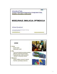
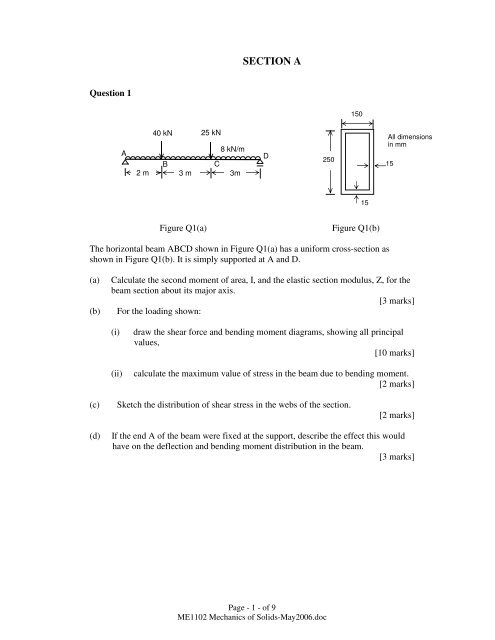
The horizontal beam ABCD shown in Figure Q1(a) has a uniform cross-section as<br />
shown in Figure Q1(b). It is simply supported at A and D.<br />
(a)<br />
(b)<br />
Calculate the second moment <strong>of</strong> area, I, and the elastic section modulus, Z, for the<br />
beam section about its major axis.<br />
[3 marks]<br />
For the loading shown:<br />
(i)<br />
(ii)<br />
draw the shear force and bending moment diagrams, showing all principal<br />
values,<br />
[10 marks]<br />
calculate the maximum value <strong>of</strong> stress in the beam due to bending moment.<br />
[2 marks]<br />
(c)<br />
Sketch the distribution <strong>of</strong> shear stress in the webs <strong>of</strong> the section.<br />
[2 marks]<br />
(d)<br />
If the end A <strong>of</strong> the beam were fixed at the support, describe the effect this would<br />
have on the deflection and bending moment distribution in the beam.<br />
[3 marks]<br />
Page - 1 - <strong>of</strong> 9<br />
<strong>ME1102</strong> <strong>Mechanics</strong> <strong>of</strong> <strong>Solids</strong>-May2006.doc
Question 2<br />
60 kN<br />
20 kN<br />
A<br />
B<br />
C<br />
D<br />
5m<br />
3m<br />
Figure Q2<br />
2m<br />
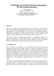
The uniform beam, ABCD, shown in Figure Q2 is simply supported at its end, A and<br />
propped at C. The beam carries concentrated loads <strong>of</strong> 60 kN at B and 20 kN at D.<br />
The modulus <strong>of</strong> elasti<strong>city</strong> <strong>of</strong> the material <strong>of</strong> the beam is 205 x 10 3 N/mm 2 and the second<br />
moment <strong>of</strong> area <strong>of</strong> the beam about the axis <strong>of</strong> bending is 120 x 10 6 mm 4 .<br />
(a) Sketch the deflected form, indicating points where the deflection, slope or<br />
curvature are zero.<br />
[2 marks]<br />
(b) Find the position and value <strong>of</strong> the maximum deflection <strong>of</strong> the beam.<br />
[18 marks]<br />
Page - 2 - <strong>of</strong> 9<br />
<strong>ME1102</strong> <strong>Mechanics</strong> <strong>of</strong> <strong>Solids</strong>-May2006.doc
Question 3<br />
40 kN<br />
1.5 m 1.5 m<br />
40 kN<br />
D<br />
B<br />
A<br />
1.5 m<br />
E<br />
C<br />
Figure Q3<br />
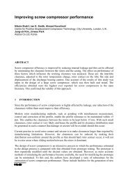
The pin-jointed truss shown in Figure Q3 lies in a vertical plane and is pinned to a<br />
vertical, rigid support at D and E.<br />
(a) Find the force in e<strong>ac</strong>h member <strong>of</strong> the truss due to the loading shown.<br />
[14 marks]<br />
(b) Find the magnitudes and directions <strong>of</strong> the re<strong>ac</strong>tions at D and E.<br />
[6 marks]<br />
Page - 3 - <strong>of</strong> 9<br />
<strong>ME1102</strong> <strong>Mechanics</strong> <strong>of</strong> <strong>Solids</strong>-May2006.doc
Question 4<br />
(a)<br />
A circular, hollow shaft has a cross-section with an external diameter <strong>of</strong> 100 mm<br />
and wall thickness 15 mm. It has a length <strong>of</strong> 1.5 m and transmits a torque <strong>of</strong> 15<br />
kNm when rotating at 300 revolutions per minute. The shear modulus, G, for the<br />
material <strong>of</strong> the shaft is 78 x 10 3 N/mm 2 .<br />
Find:<br />
(i) the maximum shear stress in the shaft<br />
(ii) the angle <strong>of</strong> twist<br />
(iii) the power transmitted.<br />
[6 marks]<br />
[4 marks]<br />
[2 marks]<br />
(b)<br />
A solid circular shaft has the same length and mass. What torque would be<br />
transmitted if the maximum shear stress were the same as for the hollow shaft?<br />
[8 marks]<br />
Page - 4 - <strong>of</strong> 9<br />
<strong>ME1102</strong> <strong>Mechanics</strong> <strong>of</strong> <strong>Solids</strong>-May2006.doc
SECTION B<br />
Question 5<br />
(a) Car A is travelling along a straight motorway, while car B is moving along a circular<br />
exit ramp <strong>of</strong> 100 m radius. The speed <strong>of</strong> A is being increased at a rate <strong>of</strong> 1.6 m/s 2 while<br />
car B is moving with a constant velo<strong>city</strong> <strong>of</strong> 12 m/s. For the position shown, determine:<br />
(i) the velo<strong>city</strong> <strong>of</strong> A relative to B and its direction (to horizontal axis) from a<br />
velo<strong>city</strong> vector diagram or any other method.<br />
[5 marks]<br />
(ii) the <strong>ac</strong>celeration <strong>of</strong> A relative to B and its direction [7 marks]<br />
A<br />
V A = 22 m/s<br />
30 o 100 m<br />
B<br />
V B = 12 m/s<br />
Figure Q5(a)<br />
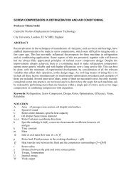
(b) The bar OB is supported at O and held in a vertical position by three cables AC, AD<br />
and BE, figure Q5(b). If the tension in the cable BE is T =453.5i -151.2j – 1209.2k,<br />
determine:<br />
(i) The magnitude <strong>of</strong> tension force. [1 marks]<br />
(ii) The moment <strong>of</strong> this vector T with respect to base <strong>of</strong> the pillar at O. [7 marks]<br />
z<br />
B<br />
A<br />
D<br />
T<br />
y<br />
C<br />
O<br />
4.5<br />
All dimension in m<br />
OB=12 m<br />
E<br />
1.5<br />
x<br />
Figure Q5 (b)<br />
Page - 5 - <strong>of</strong> 9<br />
<strong>ME1102</strong> <strong>Mechanics</strong> <strong>of</strong> <strong>Solids</strong>-May2006.doc
Question 6<br />
The van shown in Fig. Q6 has a mass 1800 kg with mass centre at G. The coefficient <strong>of</strong><br />
friction between the tyres and the road surf<strong>ac</strong>e is 0.75. The brakes are applied when the<br />
van is travelling down a slop <strong>of</strong> 5 degrees and at this instant all the wheels are on the<br />
point <strong>of</strong> slipping.<br />
(a) Draw an appropriate free body diagram<br />
[4 marks]<br />
(b) Calculate:<br />
(i) the deceleration <strong>of</strong> the van [8 marks]<br />
(ii) the distance required that the van comes to rest from a speed <strong>of</strong> 100.8 km/h<br />
[3 marks]<br />
(ii) the normal forces at the front and rear wheels. [5 marks]<br />
100.8 km/h<br />
0.6 m<br />
G<br />
1.7 m 1.3 m<br />
θ<br />
=<br />
Figure Q6<br />
Page - 6 - <strong>of</strong> 9<br />
<strong>ME1102</strong> <strong>Mechanics</strong> <strong>of</strong> <strong>Solids</strong>-May2006.doc
Question7<br />
The unbalanced 25 kg flywheel shown in Fig. Q7 has a radius <strong>of</strong> gyration <strong>of</strong> 0.18 m<br />
about an axis passing through its mass centre G. If it has a clockwise angular velo<strong>city</strong> <strong>of</strong><br />
8 rad/s at the instant shown, draw the free body diagram and mass <strong>ac</strong>celeration diagram.<br />
[5 marks]<br />
Also determine:<br />
(a) the angular <strong>ac</strong>celeration <strong>of</strong> the flywheel<br />
[10 marks]<br />
(b) the horizontal and vertical re<strong>ac</strong>tion forces at O<br />
[5 marks]<br />
ω = 8 rad/s<br />
0.15 m<br />
120 N.m<br />
O<br />
G<br />
Figure Q7<br />
Page - 7 - <strong>of</strong> 9<br />
<strong>ME1102</strong> <strong>Mechanics</strong> <strong>of</strong> <strong>Solids</strong>-May2006.doc
Question 8<br />
In the forging device shown in Fig. Q8, The 40 kg hammer is lifted to position 1 and<br />
released from rest. It falls and strikes a 20 kg pile embedded in the wood when it is in<br />
position 2. The two identical springs have a constant <strong>of</strong> k=1500 N/m, and the tension in<br />
e<strong>ac</strong>h spring is 150 N when the hammer is in position 2. Neglect friction between the<br />
hammer and slide bars and calculate:<br />
(a) the unstretched length <strong>of</strong> the springs.<br />
[5 marks]<br />
(b) the velo<strong>city</strong> <strong>of</strong> the hammer just before it strikes the pile by using the conservation<br />
<strong>of</strong> energy .<br />
[10 marks]<br />
(c) the velo<strong>city</strong> <strong>of</strong> pile immediately after the imp<strong>ac</strong>t if the hammer velo<strong>city</strong> is<br />
reduced to 1.7 m/s.<br />
[5 marks]<br />
Hammer<br />
1<br />
300 mm<br />
k<br />
k<br />
400<br />
mm<br />
2<br />
Pile<br />
Figure Q8<br />
DATA SHEET<br />
Page - 8 - <strong>of</strong> 9<br />
<strong>ME1102</strong> <strong>Mechanics</strong> <strong>of</strong> <strong>Solids</strong>-May2006.doc
PART I MECHANICS OF SOLID<br />
One-dimensional motion<br />
2<br />
ds<br />
ds d s<br />
v =<br />
a = =<br />
2<br />
dt<br />
dt dt<br />
Constant velo<strong>city</strong>, a=0 s = s o +vt<br />
Constant Acceleration v=v o +at s=s o +v o t+ 2<br />
1 at<br />
2<br />
dv<br />
= v<br />
ds<br />
Curvilinear motion<br />
Cartesian (rectangular) co-ordinates<br />
Position vector<br />
r =xi+yj+zk<br />
Velo<strong>city</strong> vector<br />
v = v i+<br />
x<br />
v y<br />
j+ v z<br />
k = x& i+ y& j+ z& k<br />
Acceleration<br />
a = a i+<br />
x<br />
a y<br />
j+ a z<br />
k = & x& i+ & y& j+ & z& k<br />
Normal (n) and tangential (t) coordinates<br />
v 2 = v o 2 +2as<br />
velo<strong>city</strong> v = v e t = rω e t = rθ & e t Acceleration a = e n + v& e<br />
r t<br />
a n =v 2 2 2<br />
/r a t = v& =dv/dt a = a n<br />
+ a t<br />
Radial-Transverse (Polar) coordinates<br />
Position vector r = r e r<br />
Velo<strong>city</strong> vector v = r& e r + rθ & e θ<br />
Acceleration a = (& r& - rθ & 2 )e r + (2 r& & θ + rθ & ) e θ<br />
a r =( & r& - rθ & 2 ) a θ =(2 r& & θ + rθ & 2<br />
) a = a +<br />
r<br />
v 2<br />
2<br />
a θ<br />
Rigid body plane motion<br />
∑M G =I G α<br />
∑M o =I G α+ma G d<br />
Energy equation<br />
∆U= ∆KE + ∆PE+ ∆SE where ∆KE=0.5mv 2 , ∆PE =mgh and<br />
Strain energy SE = V e = 2<br />
1 k x<br />
2<br />
Kinetic energy <strong>of</strong> rigid body in plane motion KE= T = 2<br />
1 mvG<br />
2<br />
+ 2<br />
1<br />
ΙG ω 2<br />
Coefficient <strong>of</strong> Restitution<br />
e =<br />
v<br />
u<br />
B<br />
−<br />
v<br />
u<br />
A B<br />
=<br />
−<br />
A<br />
relative<br />
relative<br />
velo<strong>city</strong><br />
velo<strong>city</strong><br />
<strong>of</strong><br />
<strong>of</strong><br />
separation<br />
appro<strong>ac</strong>h<br />
Moment <strong>of</strong> a Force<br />
M=r x F= (rFsinθ)<br />
e p<br />
Page - 9 - <strong>of</strong> 9<br />
<strong>ME1102</strong> <strong>Mechanics</strong> <strong>of</strong> <strong>Solids</strong>-May2006.doc