The correct way to bond shields - Resolution
The correct way to bond shields - Resolution
The correct way to bond shields - Resolution

Create successful ePaper yourself
Turn your PDF publications into a flip-book with our unique Google optimized e-Paper software.
technology<br />
<strong>The</strong> <strong>correct</strong> <strong>way</strong> <strong>to</strong> <strong>bond</strong><br />
cable <strong>shields</strong><br />
Recent coverage of the <strong>to</strong>pic in the pages of this magazine have begged explanation of the whole double-ended shield <strong>bond</strong>ing issue.<br />
<strong>The</strong> knowledge base and the substantiating proof exists, according <strong>to</strong> KEITH ARMSTRONG and TONY WALDRON.<br />
WHEN WE WERE LEARNING how <strong>to</strong> do<br />
pro audio decades ago, we learnt that<br />
experienced engineers minimised the noise<br />
in a mixing console by spending a great deal of time<br />
‘fiddling about’ with the terminations of its cable<br />
<strong>shields</strong> and its internal <strong>bond</strong>ing.<br />
Despite the fact that the console’s electronics<br />
modules worked satisfac<strong>to</strong>rily on the bench, they<br />
behaved quite differently when connected <strong>to</strong>gether in<br />
a console frame – and differently again when finally<br />
installed on the cus<strong>to</strong>mer’s site. <strong>The</strong> main problem was<br />
interference known as ‘hum’ or ‘buzz’ and the purpose<br />
of the lengthy fiddling about was <strong>to</strong> ‘eliminate the<br />
hum loops’ (sometimes called ground loops).<br />
In recent years we have discovered this expensive<br />
‘fiddling about’ was all unnecessary. Because of a<br />
design decision made many decades ago, possibly<br />
even for no very good reason, and repeated as if it<br />
were gospel ever since, single-point grounding<br />
techniques and single-ended cable shield <strong>bond</strong>ing<br />
became the standard for equipment design. As a direct<br />
result of this poor decision pro audio equipment and<br />
systems were condemned <strong>to</strong> suffer hums and buzzes<br />
requiring costly devices with high common-mode<br />
rejection ratio (CMRR) and/or time-consuming<br />
‘fiddling about’ <strong>to</strong> solve.<br />
It <strong>to</strong>ok the introduction of digital technology and the<br />
EMC directive with its EMC standards EN 55103-1 and<br />
-2 <strong>to</strong> force us <strong>to</strong> abandon our decades-old practices.<br />
Now we use mesh-<strong>bond</strong>ing techniques and <strong>bond</strong> the<br />
<strong>shields</strong> of our cables <strong>to</strong> chassis at both ends – a process<br />
of discovery described [1] by Tony Waldron.<br />
new and legacy pro audio installations have already<br />
benefited greatly from the use of our new techniques.<br />
Equipment should be designed so as <strong>to</strong> <strong>bond</strong> the<br />
<strong>shields</strong> of every cable (digital or analogue) <strong>to</strong> its local<br />
chassis or frame – ideally <strong>to</strong> the surface of its Faraday<br />
cage enclosure shield, if it has one. This is not a recent<br />
revelation – the Audio Engineering Society devoted a<br />
full issue of its Journal <strong>to</strong> it in 1995 [5], and John<br />
Watkinson described its benefits in Studio Sound in<br />
1995 [2], in 1996 [3], and most recently in the<br />
July/August 2002 issue of <strong>Resolution</strong> [4].<br />
Next, both ends of every cable shield should be<br />
<strong>bond</strong>ed directly <strong>to</strong> their local chassis or Faraday cage<br />
as specified by IEC 61000-5-2 [6]. Of course, this<br />
causes ground loop currents <strong>to</strong> flow in the cable<br />
<strong>shields</strong>, but we have recently shown [7] that this<br />
cannot cause significant audio noise – even in the very<br />
highest quality systems – even with shield currents<br />
large enough <strong>to</strong> heat the cables.<br />
Our article [7] in the EMC Compliance Journal<br />
describes tests on a variety of balanced audio cables<br />
nearly 30m long <strong>to</strong> determine the effects of powerfrequency<br />
shield currents on audio<br />
noise. Several types of balanced cables<br />
were tested, including an extremely poor<br />
quality cable with untwisted signal<br />
conduc<strong>to</strong>rs and a capacitive imbalance<br />
exceeding 20% – representing the worst<br />
legacy cabling that can be expected.<br />
No properly managed pro audio system<br />
has ground potential differences large<br />
enough <strong>to</strong> drive damaging currents in<br />
cable <strong>shields</strong>, although they can occur in<br />
heavy industry and during ground-faults.<br />
In any case, the solution is simply <strong>to</strong> run<br />
a parallel earth conduc<strong>to</strong>r (PEC) between<br />
the offending items of equipment, as<br />
described in IEC 61000-2-5 [6].<br />
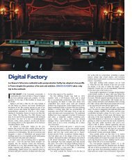
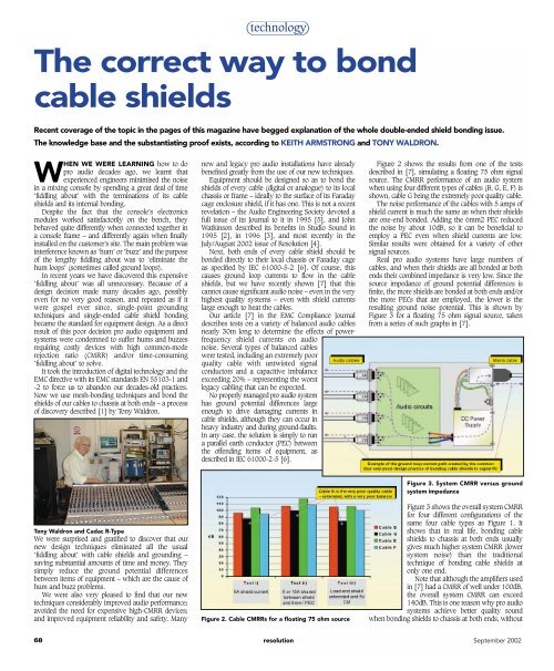
Figure 2 shows the results from one of the tests<br />
described in [7], simulating a floating 75 ohm signal<br />
source. <strong>The</strong> CMRR performance of an audio system<br />
when using four different types of cables (B, G, E, F) is<br />
shown, cable G being the extremely poor quality cable.<br />
<strong>The</strong> noise performance of the cables with 5 amps of<br />
shield current is much the same as when their <strong>shields</strong><br />
are one-end <strong>bond</strong>ed. Adding the 6mm2 PEC reduced<br />
the noise by about 10dB, so it can be beneficial <strong>to</strong><br />
employ a PEC even when shield currents are low.<br />
Similar results were obtained for a variety of other<br />
signal sources.<br />
Real pro audio systems have large numbers of<br />
cables, and when their <strong>shields</strong> are all <strong>bond</strong>ed at both<br />
ends their combined impedance is very low. Since the<br />
source impedance of ground potential differences is<br />
finite, the more <strong>shields</strong> are <strong>bond</strong>ed at both ends and/or<br />
the more PECs that are employed, the lower is the<br />
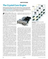
resulting ground noise potential. This is shown by<br />
Figure 3 for a floating 75 ohm signal source, taken<br />
from a series of such graphs in [7].<br />
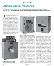
Tony Waldron and Cadac R-Type<br />
We were surprised and gratified <strong>to</strong> discover that our<br />
new design techniques eliminated all the usual<br />
‘fiddling about’ with cable <strong>shields</strong> and grounding –<br />
saving substantial amounts of time and money. <strong>The</strong>y<br />
simply reduce the ground potential differences<br />
between items of equipment – which are the cause of<br />
hum and buzz problems.<br />
We were also very pleased <strong>to</strong> find that our new<br />
techniques considerably improved audio performance;<br />
avoided the need for expensive high-CMRR devices;<br />
and improved equipment reliability and safety. Many<br />
Figure 2. Cable CMRRs for a floating 75 ohm source<br />
Figure 3. System CMRR versus ground<br />
system impedance<br />
Figure 3 shows the overall system CMRR<br />
for four different configurations of the<br />
same four cable types as Figure 1. It<br />
shows that in real life, <strong>bond</strong>ing cable<br />
<strong>shields</strong> <strong>to</strong> chassis at both ends usually<br />
gives much higher system CMRR (lower<br />
system noise) than the traditional<br />
technique of <strong>bond</strong>ing cable <strong>shields</strong> at<br />
only one end.<br />
Note that although the amplifiers used<br />
in [7] had a CMRR of well under 100dB,<br />
the overall system CMRR can exceed<br />
140dB. This is one reason why pro audio<br />
systems achieve better quality sound<br />
when <strong>bond</strong>ing <strong>shields</strong> <strong>to</strong> chassis at both ends, without<br />
68 resolution September 2002
technology<br />
the need for costly high-CMRR devices such as special<br />
transformers.<br />
Bonding cable <strong>shields</strong> <strong>to</strong> chassis with ‘pigtails’ (a<br />
length of wire and/or a connec<strong>to</strong>r pin), as XLR and<br />
many other standard audio connec<strong>to</strong>rs often force us<br />
<strong>to</strong> do, is sufficient for eliminating hum and buzz<br />
interference caused by mains frequencies, but useless<br />
at preventing radio-frequency (RF) interference.<br />
Controlling the emissions of, and susceptibility <strong>to</strong>,<br />
interference is known as EMC. Most readers will know<br />
that all pro audio, video, and entertainment lighting<br />
equipment and systems supplied in Europe must by<br />
law meet the EU’s EMC Directive by applying the<br />
harmonised standards EN 55103-1 and EN 55103-2,<br />
affixing the CE mark and having a signed Declaration<br />
of Conformity. (An alternative is known as the<br />
Technical Construction File route.)<br />
Designing equipment <strong>to</strong> employ RF shield<br />
terminations at both ends of typical shielded audio<br />
cables helps achieve EMC compliance at the lowest<br />
cost, by considerably reducing the size and cost of the<br />
filters that would otherwise be needed at every input<br />
and output. Happily, some audio connec<strong>to</strong>r<br />
manufacturers can now supply products that use<br />
reasonable RF shield <strong>bond</strong>ing techniques.<br />
Some people have been recommending capacitive<br />
shield <strong>bond</strong>ing at one cable end <strong>to</strong> help achieve good<br />
EMC, but this would still require ‘fiddling<br />
about’ and the use of expensive high-<br />
CMRR devices for the highest quality.<br />
For good EMC performance <strong>to</strong> 1000MHz<br />
as required by EN 55103-1 and -2 the<br />
special capacitive connec<strong>to</strong>rs required<br />
would be costly, and will often need <strong>to</strong><br />
be fitted at both ends of the cable <strong>to</strong><br />
permit the traditional time-consuming<br />
‘fiddling about’.<br />
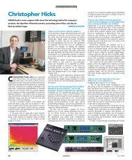
Poor equipment design is the real<br />
cause of ‘hum loop’ noise. Shield<br />
currents have got such a bad reputation<br />
for causing noise because most legacy<br />
equipment was designed using very<br />
poor shield <strong>bond</strong>ing practices, such as<br />
the method shown in Figure 4.<br />
Figure 4. It is poor equipment design that causes<br />
‘ground loop’ noise<br />
Ground loop currents in cable <strong>shields</strong> are injected in<strong>to</strong><br />
the finite impedances of a sensitive audio circuit’s 0V<br />
system, causing noise voltages <strong>to</strong> arise in the 0V<br />
references of the unbalanced audio circuits and<br />
making their signals noisy. Very careful use of singlepoint<br />
grounding can go some <strong>way</strong> <strong>to</strong> reducing this<br />
problem, but the stray magnetic coupling between<br />
wires and PCB traces means that shield currents will<br />
al<strong>way</strong>s cause unacceptable hums and buzzes.<br />
Another traditional but very poor technique is <strong>to</strong><br />
use a ‘chassis’ trace (or wire) <strong>to</strong> connect all the shield<br />
pins <strong>to</strong>gether and (eventually) connect them <strong>to</strong> the<br />
chassis. <strong>The</strong>se ‘chassis ground’ traces are isolated from<br />
0V but magnetically couple with any nearby signal or<br />
0V traces or wires, giving rise <strong>to</strong> noise voltages.<br />
All these noise problems would be eliminated if<br />
cable <strong>shields</strong> were connected directly <strong>to</strong> the<br />
chassis/frame/enclosure at the point where their cable<br />
enters the equipment (as recommended by [2], [3],<br />
[4], [5] and [6]) and this is also best for EMC. A<br />
surprising proportion of new equipment still uses longdiscredited<br />
shield <strong>bond</strong>ing methods.<br />
Although grounding system resistances are usually<br />
less than 2 ohms, their inductance makes their<br />
impedance <strong>to</strong> lightning and other types of voltage<br />
surge much higher.<br />
Reference [8] shows that the effect is <strong>to</strong> apply most<br />
of the surge voltage <strong>to</strong> the electronic devices at cable<br />
ends where <strong>shields</strong> are not <strong>bond</strong>ed <strong>to</strong> chassis, and this<br />
Figure 5. Surge overvoltages caused at<br />
signal inputs and outputs<br />
is very bad for reliability (Figure 5).<br />
Bonding cable <strong>shields</strong> at both ends and<br />
using PECs where appropriate<br />
considerably reduces the inductance of the<br />
grounding system, reducing the surge<br />
voltages that develop as well as helping <strong>to</strong><br />
protect input and output devices from<br />
overvoltages.<br />
<strong>The</strong> ends of cables that have<br />
unterminated <strong>shields</strong> have occasionally<br />
been seen <strong>to</strong> flash-over during<br />
thunders<strong>to</strong>rms, so there are clearly<br />
significant shock and fire hazards<br />
associated with <strong>bond</strong>ing cable <strong>shields</strong> at one end.<br />
Finally, it is a common practice in the pro audio industry<br />
<strong>to</strong> disconnect the protective ground conduc<strong>to</strong>rs from<br />
items of equipment <strong>to</strong> help ‘cure’ hum loops quickly and<br />
at low cost. This is a very bad practice indeed, and is<br />
illegal under health and safety legislation in many<br />
countries. When cable <strong>shields</strong> are <strong>bond</strong>ed at both ends<br />
this traditional (but unsafe) remedy is not required.<br />
In conclusion, <strong>bond</strong>ing the <strong>shields</strong> of balanced<br />
cables at only one end only achieves good noise<br />
performance for complex installations after a great deal<br />
of costly ‘fiddling about’, and also wastes a low-cost<br />
EMC resource.<br />
Concerns about ‘hum loop’ noise when <strong>bond</strong>ing both<br />
ends of the <strong>shields</strong> of balanced audio cables are without<br />
basis for <strong>correct</strong>ly designed equipment. Correct equipment<br />
design need cost little more and helps achieve EMC<br />
compliance at lowest cost by using the EMC performance<br />
of existing cable <strong>shields</strong>. As the number of cable <strong>shields</strong><br />
<strong>bond</strong>ed at both ends in an installation increases, and/or as<br />
more PECs are used, the noisy ground potential<br />
differences in an installation fall and so do the resulting<br />
CM noise voltages. <strong>The</strong> large number of shielded cables<br />
available in a typical pro audio installation make it easy <strong>to</strong><br />
reduce ground noise potentials dramatically –<br />
substantially increasing the system’s overall CMRR.<br />
Even where EMC compliance is not a necessity,<br />
<strong>bond</strong>ing cable <strong>shields</strong> at both ends saves large<br />
amounts of time and cost by <strong>to</strong>tally eliminating any<br />
need <strong>to</strong> ‘fiddle about’ with hum loops. It also improves<br />
sound system quality, reliability, and safety. ■<br />
Contacts<br />
Tony Waldron is technical manager for Cadac and former<br />
sound designer at <strong>The</strong> Royal Danish <strong>The</strong>atre, Copenhagen<br />
and head of sound at <strong>The</strong> National <strong>The</strong>atre, London.<br />
Tel: +44 1582 404202<br />
E-mail: <strong>to</strong>ny@cadac-sound.com<br />
Website: www.cadac-sound.com<br />
Keith Armstrong specialises in EMC and safety<br />
compliance for Cherry Clough Consultants and previously<br />
designed high-performance analogue circuits, A-D and D-A<br />
conver<strong>to</strong>rs for Neve<br />
mixing desks.<br />
Tel: +44 1457 871605<br />
E-mail: keith.armstrong@cherryclough.com<br />
Website: www.cherryclough.com<br />
1 Designing for interference-free audio system<br />
components, Tony Waldron, EMC Compliance<br />
Journal, July 2002, p22 (www.complianceclub.com)<br />
2 EMC: who’s really afraid now? John Watkinson,<br />
Studio Sound, Oc<strong>to</strong>ber 1995, p13<br />
3 Money for old cabling, John Watkinson, Studio<br />
Sound, September 1996, p89<br />
4 <strong>The</strong> cable snake, John Watkinson, <strong>Resolution</strong>,<br />
July/August 2002, p57<br />
5 Journal of the AES: Volume 43, Number 6,<br />
1995, Special Excerpt – Shields and Grounds.<br />
6 IEC 61000-5-2:1997 Electromagnetic<br />
compatibility (EMC) – Part 5: Installation and<br />
mitigation guidelines – Section 2: Grounding<br />
and cabling<br />
7 Bonding cable <strong>shields</strong> at both ends <strong>to</strong> reduce<br />
noise, Tony Waldron and Keith Armstrong, EMC<br />
Compliance Journal, May 2002, p14<br />
8 Bonding the screens of cables at both<br />
ends, Keith Armstrong, ERA Conference<br />
‘Earthing 2000’ 21-22 June 2000, Solihull<br />
(www.eratechnology.co.uk)<br />
September 2002<br />
resolution<br />
69