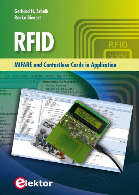
RFID - Elektor
RFID - Elektor
RFID - Elektor
Create successful ePaper yourself
Turn your PDF publications into a flip-book with our unique Google optimized e-Paper software.
copyright <strong>Elektor</strong>
Contents<br />
Preface ................................................... 13<br />
1 <strong>RFID</strong> Fundamentals ...................................... 17<br />
1.1 Introduction to <strong>RFID</strong> .................................. 17<br />
1.1.1 RF .......................................... 17<br />
1.1.2 ID .......................................... 18<br />
1.1.3 <strong>RFID</strong> system classification ......................... 19<br />
1.1.3.1 Frequencies and transmission principles ......... 19<br />
1.1.3.2 Applications ............................. 20<br />
1.2 <strong>RFID</strong> system components .............................. 22<br />
1.2.1 Card (PICC) ................................... 22<br />
1.2.2 Reader (PCD) .................................. 23<br />
1.3 ISO/IEC 14443 application example ....................... 24<br />
1.3.1 Public transport ticketing .......................... 24<br />
1.3.2 Employee identification cards ....................... 25<br />
1.3.3 Electronic passports and identity cards ................ 26<br />
1.3.4 Other applications ............................... 27<br />
1.4 Physical fundamentals ................................. 27<br />
1.4.1 Energy transmission. ............................. 27<br />
1.4.2 Data transmission from PCD to PICC .................. 29<br />
1.4.2.1 Amplitude modulation ...................... 29<br />
1.4.2.2 Standard data rate (106 Kb/s) ................ 29<br />
1.4.2.3 Higher data rates (up to 848 Kb/s) ............. 31<br />
1.4.3 Data transmission from PICC to PCD .................. 32<br />
1.4.3.1 Load modulation. ......................... 33<br />
1.4.3.2 Subcarrier modulation:<br />
Manchester encoding using ASK ............... 33<br />
1.4.3.3 Subcarrier modulation:<br />
NRZ encoding with BPSK .................... 34<br />
copyright <strong>Elektor</strong><br />
2 Overview of the Relevant Standards ......................... 35<br />
2.1 ISO/IEC 14443 ....................................... 35<br />
2.1.1 Part 1: physical properties ......................... 36<br />
2.1.2 Part 2: RF properties and signals ..................... 37<br />
2.1.3 Part 3: Card selection and activation ................... 38<br />
2.1.3.1 Type A: UIDs ............................ 38<br />
2.1.3.2 Type A: card activation ..................... 40<br />
2.1.3.3 Type A: SAK encoding ...................... 42<br />
2.1.3.4 Type A: collision-detection and<br />
conflict resolution ........................ 44<br />
2.1.3.5 Type B card activation ...................... 46<br />
2.1.3.6 Type B: Card activation parameters ............ 48
Contents<br />
2.1.4 Part 4: communication protocol ...................... 49<br />
2.1.4.1 Protocol activation ......................... 49<br />
2.1.4.2 T=CL protocol block structure. ................ 56<br />
2.1.5 Information Block (I Block) ......................... 56<br />
2.1.5.1 Receive-ready Blocks (R Blocks) ............... 58<br />
2.1.5.2 Supervisory Blocks (S Blocks) ................ 59<br />
2.1.6 Electromagnetic disturbance (EMD) ................... 61<br />
2.1.6.1 Rest period .............................. 62<br />
2.1.6.2 Rest level ................................ 63<br />
2.1.6.3 Distinction between invalid card<br />
response and EMD ........................ 63<br />
2.1.6.4 The MFRC522 reader IC and EMD ............... 63<br />
2.2 ISO/IEC 10373-6 test methods. ........................... 64<br />
2.2.1 Test equipment ................................. 65<br />
2.2.1.1 Calibration coil ........................... 65<br />
2.2.1.2 Test PCD assembly ........................ 65<br />
2.2.1.3 ReferencePICC ........................... 66<br />
2.2.2 Tuning and calibration ............................ 68<br />
2.2.2.1 Tuning ................................. 68<br />
2.2.2.2 Calibration .............................. 68<br />
2.2.3 Measurements at the reader ........................ 69<br />
2.2.3.1 Range measurement ....................... 69<br />
2.2.3.2 Measurement effort ........................ 69<br />
2.2.4 Tests for Layer 3 and 4 ............................ 70<br />
2.3 Near Field Communication (NFC) .......................... 70<br />
2.3.1 Introduction ................................... 70<br />
2.3.2 NFC air interface ................................ 71<br />
2.3.2.1 NFC device as card ........................ 71<br />
2.3.2.2 NFC device as a reader ..................... 71<br />
2.3.2.3 NFC device in ‘active’ mode .................. 72<br />
copyright <strong>Elektor</strong><br />
3 <strong>RFID</strong> Antenna Design ..................................... 73<br />
3.1 Theoretical Fundamentals ............................... 73<br />
3.1.1 Antenna as Resonant Circuit ........................ 73<br />
3.1.2 Transformer Model ............................... 77<br />
3.1.3 The Biot-Savart Law .............................. 79<br />
3.1.4 Optimal Antenna Size ............................. 80<br />
3.2 Reader Antennas ..................................... 83<br />
3.2.1 Antenna Quality ................................. 83<br />
3.2.1.1 Data Transmission Bandwidth ................. 83<br />
3.2.1.2 Stability Against Detuning ................... 86<br />
3.2.2 Electrically Conductive Surfaces in the Vicinity<br />
of the Antenna ................................... 89<br />
3.2.2.1 Ferrites ................................ 90<br />
3.2.3 Balanced and Unbalanced Antennas ................... 92<br />
3.2.3.1 Balanced Antenna ......................... 93<br />
3.2.3.2 Unbalanced Antenna ....................... 96<br />
4
CONTENTS<br />
3.3 Card Antennas ....................................... 98<br />
3.3.1 Standard Cards (ID-1) ............................ 98<br />
3.3.2 Tokens with Smaller Inlays (Smaller than ID-1) ........... 100<br />
3.4 Impedance Measurements with the miniVNA .................. 101<br />
3.4.1 miniVNA User Software. ........................... 102<br />
3.4.2 Disadvantages and Limitations of the miniVNA ........... 102<br />
3.4.2.1 Lack of Sign for Imaginary Numbers . . . . . . . . . . . . 102<br />
3.4.2.2 Lack of Calibration and Compensation ........... 102<br />
3.4.3 How Do I Find the Correct Compensation? .............. 103<br />
3.4.4 Coil Inductance Measurement ....................... 105<br />
4 Security and Cryptography ................................ 109<br />
4.1 Protection Objectives .................................. 109<br />
4.1.1 Keeping Data Secure ............................. 109<br />
4.1.2 Data Integrity .................................. 111<br />
4.1.3 Privacy Protection ............................... 112<br />
4.2 Attacks on Smartcards ................................. 112<br />
4.2.1 Logical Attacks ................................. 112<br />
4.2.1.1 Unauthorized Reading of Data. ................ 112<br />
4.2.1.2 Unauthorized Manipulation of Data ............. 113<br />
4.2.1.3 ‘Replay’ Attack ........................... 114<br />
4.2.1.4 ‘Relay’ Attack ............................ 114<br />
4.2.1.5 ‘Man-in-the-Middle’ Attack ................... 116<br />
4.2.1.6 Denial-of-Service Attack .................... 116<br />
4.2.2 Physical Attacks. ................................ 116<br />
4.2.2.1 Side Channel Attacks and Power Analysis ........ 116<br />
4.2.2.2 Reverse Engineering ....................... 118<br />
4.2.2.3 Light and Laser Attacks ..................... 119<br />
4.2.2.4 Temperature and Frequency. ................. 120<br />
4.2.3 Combined Attacks ............................... 120<br />
4.3 Cryptography ........................................ 120<br />
4.3.1 Asymmetric Cryptography. ......................... 120<br />
4.3.2 Symmetric Cryptography .......................... 122<br />
4.3.3 Block and Stream Cipher .......................... 123<br />
4.3.4 Encryption Standards: DES and AES .................. 124<br />
4.3.5 DES Cascading. ................................. 125<br />
4.3.6 Operation mode ................................. 127<br />
4.3.6.1 Electronic Code Book (ECB) .................. 127<br />
4.3.6.2 Cipher Block Chaining (CBC). ................. 127<br />
4.4 Application of Cryptography .............................. 129<br />
4.4.1 Mutual Authentication ............................. 129<br />
4.4.2 Data Encryption ................................. 131<br />
4.4.3 Message Authentication Code (MAC) .................. 131<br />
4.4.4 Key Management ................................ 132<br />
4.4.4.1 Dynamic Keys ............................ 132<br />
4.4.4.2 Key Diversification. ........................ 132<br />
4.4.5 Secure Application Module (SAM). ..................... 135<br />
4.4.6 Security Assessment .............................. 135<br />
copyright <strong>Elektor</strong><br />
5
Contents<br />
5 Introduction to Cards and Tags ............................. 137<br />
5.1 Overview ........................................... 137<br />
5.1.1 Memory Cards and Microcontroller Cards ............... 137<br />
5.1.2 Advantages and Disadvantages of Contactless Cards ....... 138<br />
5.1.2.1 Robustness .............................. 138<br />
5.1.2.2 Longevity ............................... 138<br />
5.1.2.3 Usability. ............................... 138<br />
5.1.2.4 Infrastructure ............................ 138<br />
5.1.2.5 Contact Between Card and Reader ............. 139<br />
5.1.3 Dual-Interface Cards ............................. 139<br />
5.2 MIFARE ............................................ 139<br />
5.2.1 MIFARE Overview. ............................... 139<br />
5.2.1.1 Success Story ............................ 140<br />
5.2.1.2 MIFARE Clone ............................ 140<br />
5.2.1.3 MIFARE Hack ............................ 140<br />
5.2.1.4 MIFARE Product Overview ................... 140<br />
5.2.2 MIFARE Ultralight ................................ 141<br />
5.2.2.1 Instruction Set . . . . . . . . . . . . . . . . . . . . . . . . . . . . 142<br />
5.2.2.2 Memory Organization ...................... 144<br />
5.2.2.3 Security Functions ........................ 144<br />
5.2.3 MIFARE Ultralight C .............................. 145<br />
5.2.3.1 Instruction Set ........................... 146<br />
5.2.3.2 Memory Organization ...................... 147<br />
5.2.3.3 Security Functions. ........................ 147<br />
5.2.4 MIFARE Classic ................................. 148<br />
5.2.4.1 Instruction Set ........................... 150<br />
5.2.4.2 Memory Organization ...................... 151<br />
5.2.4.3 Security Functions. ........................ 152<br />
5.2.5 MIFARE Plus ................................... 152<br />
5.2.5.1 Memory Organization ...................... 152<br />
5.2.5.2 MIFARE Plus S and MIFARE Plus X .............. 152<br />
5.2.5.3 Security Levels ........................... 153<br />
5.2.6 MIFARE DESFire (EV1) ............................ 156<br />
5.2.6.1 Memory Organization. ...................... 156<br />
5.2.6.2 File Types ............................... 157<br />
5.2.6.3 Data File ............................... 157<br />
copyright <strong>Elektor</strong><br />
6 Reader Antenna Design ................................... 159<br />
6.1 MF RC522 Reader Module ............................... 159<br />
6.1.1 Digital Interfaces . ............................... 160<br />
6.1.1.1 UART .................................. 160<br />
6.1.1.2 SPI ................................... 160<br />
6.1.1.3 I 2 C .................................... 160<br />
6.1.2 Oscillator. ..................................... 161<br />
6.1.3 Analog Interfaces ............................... 161<br />
6.1.3.1 Transmitter Outputs ....................... 161<br />
6.1.3.2 Receive Input ............................ 165<br />
6
CONTENTS<br />
6.1.4 Test Signals ................................... 169<br />
6.1.4.1 MFOUT ................................. 170<br />
6.1.4.2 AUX1 and AUX2. .......................... 171<br />
6.1.5 Miscellaneous .................................. 173<br />
6.1.5.1 Power Supply and GND ..................... 173<br />
6.1.5.2 Tolerances .............................. 173<br />
6.2 Antenna Design ...................................... 173<br />
6.2.1 Coil Design .................................... 174<br />
6.2.1.1 Measuring the Coil Parameters ................ 175<br />
6.2.1.2 Determine the Q Factor and the Series Resistance ... 176<br />
6.2.2 Matching: Calculating the Initial Values ................ 176<br />
6.2.2.1 Parallel Equivalent Circuit. ................... 176<br />
6.2.2.2 Partitioning and Simplifying the Circuit Diagram. ... 177<br />
6.2.2.3 Low-Pass Filter .......................... 177<br />
6.2.2.4 Matching Network ........................ 178<br />
6.2.3 Matching: Simulation and Measurement ............... 179<br />
6.2.4 Measurements on the Transmitted Pulse ............... 181<br />
6.2.5 Measurement and Adjustment of the Receive Path ........ 183<br />
6.2.6 Eliminating Interference .......................... 183<br />
6.2.7 Range Checking ................................. 185<br />
7 The <strong>Elektor</strong> <strong>RFID</strong> Reader .................................. 187<br />
7.1 Introduction ........................................ 187<br />
7.2 Reader Hardware ..................................... 190<br />
7.2.1 Power Supply .................................. 192<br />
7.2.2 The P89LPC936 Microcontroller ...................... 193<br />
7.2.3 The MF RC522 Reader IC .......................... 194<br />
7.2.4 The FT232R USB/RS-232 Converter ................... 197<br />
7.2.4.1 Configuring the FT232R ..................... 199<br />
7.2.4.2 USB Driver Modification ..................... 201<br />
7.3 Construction and Operation ............................. 202<br />
7.3.1 Installing the USB Driver ........................... 202<br />
7.3.2 Reader Firmware Update ........................... 203<br />
7.3.3 Firmware Version Control .......................... 205<br />
7.4 Reader Modes ........................................ 205<br />
7.4.1 Terminal Mode .................................. 205<br />
7.4.2 PC Reader Mode ................................. 207<br />
7.4.2.1 Activating the PC Reader Mode ................ 207<br />
7.5 The Firmware ........................................ 208<br />
7.5.1 The Software Architecture. ......................... 208<br />
7.5.2 The Main Program ............................... 208<br />
7.5.3 The PC_ReaderMode() Function ..................... 210<br />
7.5.3.1 The RS-232 Communication Protocol ........... 210<br />
7.6 The PC Development Tools ............................... 212<br />
7.6.1 <strong>Elektor</strong> <strong>RFID</strong> Reader Programming in .NET .............. 212<br />
7.6.2 Smart Card Magic.NET ............................ 214<br />
7.6.2.1 It’s Usable without Programming .............. 214<br />
copyright <strong>Elektor</strong><br />
7
Contents<br />
7.6.2.2 A Scripting Tool or a C# Compiler? ............. 215<br />
7.6.2.3 Our First Program: “Hello World”. .............. 216<br />
7.6.2.4 Compiling and Running. ..................... 219<br />
7.6.2.5 User Input from the Console Window ........... 220<br />
7.6.2.6 Are There Really No Breakpoints? .............. 222<br />
7.6.3 Visual C# 2012 Express Edition ...................... 223<br />
7.6.3.1 Creating a Simple Console Application ........... 223<br />
7.6.3.2 Integrating the <strong>Elektor</strong> <strong>RFID</strong> Reader Library ...... 225<br />
8 Cards and Tags in Application .............................. 227<br />
8.1 ISO/IEC 14443 Type A Card Activation ...................... 228<br />
8.1.1 Card Types from the Perspective of Card Activation ....... 228<br />
8.1.2 The Activation Sequence. .......................... 230<br />
8.1.2.1 The Request and Wake-Up Commands .......... 230<br />
8.1.2.2 The Anti-collision and Select Commands ......... 233<br />
8.1.2.3 The HALT Command ....................... 234<br />
8.1.3 <strong>Elektor</strong> <strong>RFID</strong> Reader Library: Card Activation ............ 236<br />
8.1.4 Program Examples ............................... 241<br />
8.1.4.1 Card Activation .......................... 241<br />
8.1.4.2 Reader Selection ......................... 243<br />
8.1.4.3 Polling for Cards .......................... 244<br />
8.1.4.4 Simplified Card Activation ................... 247<br />
8.1.4.5 Testing the Reading Range ................... 249<br />
8.1.4.6 Listing All Cards in the Reader’s Field ........... 250<br />
8.2 MIFARE Card-Type Detection ............................. 254<br />
8.2.1 Program Example. ............................... 255<br />
8.3 The MIFARE Ultralight Card .............................. 258<br />
8.3.1 Memory Organization ............................ 258<br />
8.3.3 Function of the One-Time-Programmable (OTP) Bytes ...... 261<br />
8.3.3.1 Lock Bits Functionality ...................... 262<br />
8.3.4 <strong>Elektor</strong> <strong>RFID</strong> Reader Library: MIFARE Ultralight ........... 263<br />
8.3.5 Program Examples .............................. 264<br />
8.3.5.1 Writing and Erasing Data .................... 264<br />
8.3.5.2 Reading the Entire Memory Contents ........... 265<br />
8.3.5.3 Reading and Writing Strings .................. 267<br />
8.3.5.4 A Simple Ticket Application .................. 268<br />
8.3.5.5 Cloning the Memory Content ................. 271<br />
8.3.5.6 Secure Data Storage ....................... 273<br />
8.4 The MIFARE Classic Card ................................ 281<br />
8.4.1 MIFARE Classic 1K Card Memory Organization. ........... 281<br />
8.4.2 MIFARE Classic 4K Card Memory Organization. ........... 281<br />
8.4.3 MIFARE Mini Card Memory Organization. ............... 282<br />
8.4.4 Instruction Set. ................................. 282<br />
8.4.5 The MIFARE Value Format .......................... 286<br />
8.4.6 Decrement, Increment, Restore and Transfer ............ 289<br />
8.4.7 Changing the Keys and Access Condition ............... 290<br />
8.4.8 <strong>Elektor</strong> <strong>RFID</strong> Reader Library: MIFARE Classic ............ 294<br />
copyright <strong>Elektor</strong><br />
8
CONTENTS<br />
8.4.8.1 The MifareClassicUtil Class ................... 294<br />
8.4.8.2 The IMifareClassic Interface ................. 297<br />
8.4.9 Program and Case Studies ......................... 300<br />
8.4.9.1 Writing and Erasing Data .................... 300<br />
8.4.9.2 Reading the Entire Memory Contents. ........... 301<br />
8.4.9.3 Optimizing the Read and Write Speeds .......... 303<br />
8.4.9.4 Optimized Reading of the Entire Memory Contents ... 307<br />
8.4.9.5 The Problem of Data Corruption ............... 310<br />
8.4.9.6 The MIFARE Value Format Methods . . . . . . . . . . . . . 314<br />
8.4.9.7 Electronic Purse with Backup Management. ....... 316<br />
8.5 The MIFARE Ultralight C Card. ............................ 322<br />
8.5.1 Memory Organization ............................. 322<br />
8.5.2 Instruction Set. ................................. 324<br />
8.5.3 Triple-DES Authentication .......................... 324<br />
8.5.4 <strong>Elektor</strong> <strong>RFID</strong> Reader Library: MIFARE Ultralight C ......... 327<br />
8.5.5 Programming Examples ........................... 327<br />
8.5.5.1 The MIFARE Ultralight C Authentication Sequence ... 327<br />
8.5.5.2 MIFARE Ultralight C Card Personalization ......... 333<br />
8.6 The T=CL Transmission Protocol ........................... 337<br />
8.6.1 T=CL Protocol Activation and Deactivation .............. 338<br />
8.6.1.1 Multi-Card Activation ....................... 341<br />
8.6.2 Data Exchange. ................................. 341<br />
8.6.2.1 Smart Card Magic.NET – Exchange Mode ......... 342<br />
8.6.2.2 Block Chaining ........................... 343<br />
8.6.2.3 Waiting Time Extension ..................... 344<br />
8.6.2.4 Error Detection and Correction ................ 344<br />
8.6.3 <strong>Elektor</strong> <strong>RFID</strong> Reader Library: T=CL ................... 345<br />
8.6.4 Example Programs ............................... 350<br />
8.6.4.1 T=CL Protocol Activation and Deactivation ........ 350<br />
8.6.4.2 Multi-Card Activation ....................... 352<br />
8.7 The MIFARE DESFire EV1 Card ............................ 355<br />
8.7.1 MIFARE DESFire EV1 Commands ..................... 356<br />
8.7.2 DESFire Native Command Structure ................... 357<br />
8.7.2.1 Card Command Structure .................... 357<br />
8.7.2.2 Card Response Structure .................... 357<br />
8.7.2.3 DESFire Block Chaining ..................... 358<br />
8.7.3 The DESFire File System ........................... 359<br />
8.7.3.1 File Types ............................... 359<br />
8.7.3.2 Data File Structure ........................ 360<br />
8.7.3.3 Directory Names .......................... 361<br />
8.7.3.4 File Names .............................. 362<br />
8.7.4 Data Structure .................................. 362<br />
8.7.5 <strong>Elektor</strong> <strong>RFID</strong> Reader Library: MIFARE DESFire EV1. ........ 362<br />
8.7.6 Example Programs ............................... 363<br />
8.7.6.1 Creating a DESFire Application ................ 363<br />
8.7.6.2 Standard Data File: Reading and Writing Data ..... 366<br />
8.8 Application Protocol Data Units (APDUs) ..................... 368<br />
8.8.1 Command APDU Data Structure. ..................... 368<br />
copyright <strong>Elektor</strong><br />
9
Contents<br />
8.8.1.1 Class Byte (CLA) .......................... 369<br />
8.8.1.2 Instruction Byte (INS) ..................... 369<br />
8.8.1.3 Parameter Bytes P1 and P2 .................. 369<br />
8.8.1.4 Coding of Length Fields Lc and Le ............. 369<br />
8.8.2 Response APDU Data Structure ...................... 371<br />
8.8.3 Examples of ISO/IEC 7816-Compatible APDUs ........... 372<br />
8.8.3.1 The SELECT Command . . . . . . . . . . . . . . . . . . . . . 372<br />
8.8.3.2 The READ BINARY Command . ................ 373<br />
8.8.3.3 The Update Binary Command ................ 375<br />
8.8.4 <strong>Elektor</strong> <strong>RFID</strong> Reader Library: APDU ................... 376<br />
8.8.5 Accessing an ISO/IEC 7816 File System ................ 378<br />
8.8.5.1 Example Program ......................... 380<br />
9 <strong>Elektor</strong> <strong>RFID</strong> Projects .................................... 385<br />
9.1 Programming the MF RC522 Reader IC ...................... 385<br />
9.1.1 <strong>Elektor</strong> <strong>RFID</strong> Reader Library: MF RC522 ................ 386<br />
9.1.2 Program Examples ............................... 386<br />
9.1.2.1 Changing the RF Parameter Configuration ........ 386<br />
9.1.2.2 MF RC522 SFR Programming — Card Activation .... 387<br />
9.2 <strong>RFID</strong> Access Control Systems. ............................ 396<br />
9.2.1 Online Systems ................................. 396<br />
9.2.2 Offline Systems ................................. 396<br />
9.2.3 <strong>Elektor</strong> <strong>RFID</strong> Reader as Access Control System ........... 396<br />
9.2.3.1 Functional Description ..................... 397<br />
9.2.3.2 Access Control Manager .................... 398<br />
9.2.3.3 Microcontroller Firmware .................... 399<br />
9.2.3.4 Reading and Deleting from the<br />
P89LPC936 EEPROM . ...................... 404<br />
9.3 An Electronic ID Card .................................. 406<br />
9.3.1 Personalization. ................................. 406<br />
9.3.2 Reading the ID Card Data .......................... 407<br />
9.4 Launching a Windows Application .......................... 408<br />
copyright <strong>Elektor</strong><br />
10 Smart Card Reader API Standards. .......................... 411<br />
10.1 Introduction ....................................... 411<br />
10.2 Card Terminal API (CT-API) ............................. 412<br />
10.3 Open Card Framework (OCF) ............................ 412<br />
10.4 Personal Computer/Smartcard (PC/SC) ..................... 413<br />
10.4.1 The PC/SC Architecture. .......................... 413<br />
10.4.1.1 Integrated Circuit Card (ICC) ................ 414<br />
10.4.1.2 Interface Device (IFD) ..................... 414<br />
10.4.1.3 Interface Device Handler (IFD Handler) ......... 414<br />
10.4.1.4 ICC Resource Manager (RM) ................. 415<br />
10.4.1.5 Service Provider ......................... 416<br />
10.4.1.6 ICC-Aware Applications .................... 417<br />
10
CONTENTS<br />
11 PC/SC Readers .......................................... 419<br />
11.1 Contactless Cards .................................... 419<br />
11.1.1 Contactless Microcontroller Smartcards ............... 419<br />
11.1.2 Contactless Memory Cards ......................... 419<br />
11.1.2.1 PC/SC-Compliant APDUs. ................... 420<br />
11.1.3 Answer To Reset (ATR) ........................... 422<br />
11.1.3.1 Contact-type Card Activation Sequence ......... 422<br />
11.1.3.2 ATR Structure of a Contact-Type Smartcard ...... 424<br />
11.1.3.3 Contactless Smartcard Pseudo-ATR Structure. .... 425<br />
11.2 The Microsoft WinSCard API. ............................ 427<br />
11.2.1 WinSCard API Programming ....................... 428<br />
11.2.1.1 Programming the WinSCard API in C ........... 430<br />
11.3 Java and PC/SC. ..................................... 438<br />
11.3.1 JPC/SC Java API ................................ 438<br />
11.3.2 Java Smartcard I/O API. .......................... 440<br />
11.4 The CSharpPCSC Wrapper for .NET ........................ 441<br />
11.4.1 How Does One Create an API Wrapper? ............... 441<br />
11.4.2 The WinSCard Class ............................. 442<br />
11.4.3 The PCSCReader Class ............................ 445<br />
11.4.4 Program Examples . ............................. 447<br />
11.4.4.1 “Hello Contactless Card”. ................... 447<br />
11.4.4.2 Determine All Installed PC/SC Drivers . ......... 449<br />
11.4.4.3 Getting the Reader and Card Properties ........ 451<br />
11.4.4.4 Testing the Reading Range .................. 452<br />
11.4.4.5 Determining the Type of<br />
Contactless Memory Card. .................. 455<br />
11.4.4.6 MIFARE Classic 1K/4K and MIFARE Ultralight. ..... 456<br />
11.4.4.7 MIFARE DESFire EV1 ...................... 459<br />
copyright <strong>Elektor</strong><br />
12 List of Abbreviations ..................................... 465<br />
13 Bibliography ............................................ 469<br />
14 Index ................................................. 471<br />
11
Preface<br />
Dr. Thomas Wille<br />
<strong>RFID</strong> technology, which uses radio frequency to identify people or objects, opens up<br />
pathways to newer and more expansive applications. From easier access control using<br />
contactless (<strong>RFID</strong>) cards to public transport fare tickets to bank cards to use in passports<br />
as well as in the new German identity cards, the applications are becoming more<br />
complex and require ever more computing power.<br />
One of the reasons for contactless technology’s success is the cards’ ease of use and<br />
convenience. Simply placing an <strong>RFID</strong> device, without any special orientation, within a<br />
few centimeters of the reader suffices, and a transaction is completed in a fraction of a<br />
second.<br />
Another advantage of this technology is its robustness. <strong>RFID</strong> devices are now highly<br />
integrated and measure just a few square millimeters in area. The coupling antennas<br />
are connected directly to the ICs’ antenna terminals, resulting in minimal anisotropic<br />
connections. The antenna and IC may then be housed very stably within a card enclosure.<br />
By minimizing the required electrical connections in this manner, there are no<br />
further mechanical-electrical connections that, from a quality perspective, could present<br />
weaknesses. It is only possible by means of this robust construction, to achieve life<br />
spans of over ten years, and to use the technology in extreme environments.<br />
copyright <strong>Elektor</strong><br />
All of these advantages are enabled with the design of more complex contactless interfaces<br />
on the cards and readers. In contrast with serial contact card interfaces with their<br />
8 contacts, data coding for <strong>RFID</strong> carriers is more complex and the high positioning tolerance<br />
in regard to the reader device is made possible by complex and robust analog<br />
interface circuitry design. Optimization of the reader–card system is also crucial for optimal<br />
implementation and robust dimensioning of <strong>RFID</strong> technology.<br />
This book gives the reader a simple and understandable introduction to the fundamentals<br />
of <strong>RFID</strong> technology and explains the relevant international standards. Then, in a<br />
separate chapter, the security aspects of the technology are discussed. Further, all <strong>RFID</strong><br />
system components are systematically presented and explained in detail, from <strong>RFID</strong><br />
antenna design to the different card and tag types to the design of an <strong>RFID</strong> reader, including<br />
the antenna design.<br />
The design of a reader, particularly the <strong>Elektor</strong> <strong>RFID</strong> Reader, is very carefully described<br />
to the user, from software/firmware to user interface. However, for the user, practical<br />
application and associated problems are the key. This is where extensive description of<br />
some <strong>Elektor</strong> <strong>RFID</strong> Reader use cases and useful tips, tricks and solutions for problem<br />
13
About the authors<br />
situations comes in. The chapters that follow fully describe the included reader software<br />
for an access control system functionally. The book also explains the user interface<br />
standards.<br />
This book is thus a systematic introduction to the <strong>RFID</strong> arena that leads the user through<br />
the design of a practical card–reader system. In addition, the book is an indispensible<br />
guide for any user who wants to conceptualize, design and optimize <strong>RFID</strong> systems, and<br />
offers the crucial assistance required for the often complex problems inherent in <strong>RFID</strong><br />
system design.<br />
With this book, the authors have closed the loop for users, hopefully aiding the continuous<br />
march of <strong>RFID</strong> technology to further, unimagined extents. For this, we owe the<br />
authors a large debt of gratitude.<br />
Hamburg, January 2011<br />
Dr. Thomas Wille<br />
Senior Director Architecture & Technology<br />
Business Unit Identification, NXP Semiconductors<br />
About the authors<br />
copyright <strong>Elektor</strong><br />
Gerhard Schalk has been an application engineer at NXP Semiconductors (formerly<br />
Philips Semiconductors) since 2001. In this role, he supports global clients in developing<br />
smartcard operating systems. He is also a freelance lecturer at the FH-Hagenberg<br />
and FH-Campus 02 (Graz) technical colleges.<br />
Renke Bienert has also been an application engineer at NXP Semiconductors since 2001.<br />
He supports global clients in developing readers and systems that use contactless smartcards.<br />
He was involved, among other things, with the introduction of electronic tickets<br />
for the 2006 FIFA World Cup, as well as electronic travel passes.<br />
14
5<br />
Introduction to<br />
Cards and Tags<br />
Renke Bienert<br />
This chapter provides an overview of the typical characteristics of (contactless) smartcards<br />
and describes the standard MIFARE contactless smartcards, which are used as<br />
much as possible in the practical part of this book (Chapters 8, 9).<br />
5.1 Overview<br />
5.1.1 Memory Cards and Microcontroller Cards<br />
The first chip cards were purely memory cards, which essentially just stored data. Today,<br />
however, this description is very limiting, as ‘simple’ storage cards have different<br />
formats as well as different storage capacities compared to our smartcards. We also<br />
expect more functions from smartcards today, such as security functions, counter functions<br />
and value calculations.<br />
copyright <strong>Elektor</strong><br />
Still, the term ‘memory card’ is quite commonly used in the smartcard arena. This term<br />
is generally used for smartcards that a system operator can purchase as a ‘finished’<br />
card and use directly. These are typically inexpensive and are used in large quantities<br />
in many applications.<br />
Reading and writing are the main features of these cards, usually associated with prior<br />
authentication and encrypted data transmission. These days, some of these ‘memory<br />
cards’ are in fact microcontroller cards, so, even if the user sees only a simple read and<br />
write interface externally, the smartcard is running software on a microcontroller.<br />
For us, microcontroller cards come into play when an operating system and software is<br />
required in order to make use of the card in an application. It could be that the card<br />
contains a generic operating system and an application may be uploaded as software<br />
(for example, a Java applet).<br />
137
5 Introduction to Cards and Tags<br />
Typically, the option to upload applications makes a card more flexible, but obviously<br />
more expensive. The card’s operating system may also have functions and storage space<br />
that aren’t needed for the application.<br />
5.1.2 Advantages and Disadvantages of Contactless Cards<br />
The more complex (expensive) the card’s features, the more likely it is to be provided<br />
with multiple interfaces.<br />
The contactless interface described in this book has many advantages over the contact<br />
interface.<br />
5.1.2.1 Robustness<br />
The IC can easily be housed completely protected within the card body, as no direct<br />
electrical or mechanical external connections are required. The readers can also be built<br />
more robustly, as no card slots or similar are required.<br />
5.1.2.2 Longevity<br />
There are no open electrical contacts that could wear out or get dirty, either on the card<br />
or the reader.<br />
5.1.2.3 Usability<br />
It is much easier, more convenient and faster to place a card on a reader then to insert<br />
it into a corresponding opening in a reader. An application in which many people could<br />
possibly want to make use of a service may not be achievable using contact cards. Consider<br />
the automatic turnstiles in a large Asian city’s subway station, and imagine that<br />
every traveler first had to insert their card into a reader slot — this would take far too<br />
long.<br />
copyright <strong>Elektor</strong><br />
Two possible disadvantages must thus be taken into account, in certain instances.<br />
5.1.2.4 Infrastructure<br />
Contact-type cards have been on the market longer than contactless cards, as have<br />
their standards, so contact-type card readers are more widespread. Also, for a long time<br />
it was cheaper to build a contact reader than a contactless one. Low-cost <strong>RFID</strong> singlechip<br />
reader ICs (for example, the MF RC523 used here) have been around for about ten<br />
years.<br />
Therefore, it may be more sensible to use contact cards in situations where systems<br />
are dependent on an infrastructure of existing readers, or in situations where either the<br />
advantages of contactless technology are not required or the number of readers (compared<br />
with the number of cards in use) is very high and so extremely low-cost readers<br />
are required.<br />
138
Overview 5.1<br />
A typical application that comes to mind is the SIM card in a cellphone. There is typically<br />
only one card per device. The cards are protected within the phone in any case<br />
and are not often changed, so abrasion of the contacts is not an issue.<br />
5.1.2.5 Contact Between Card and Reader<br />
When a contact card is in use, one can usually be fairly certain that the reader actually<br />
has direct contact with the correct card. Over-the-air communication is easier to manipulate.<br />
Therefore, there are many attack scenarios for a contactless interface. The most dangerous<br />
attack is the so-called ‘relay attack’ (Section 4.2.1.4).<br />
However, just as with contact cards, these attacks can be prevented if appropriate measures<br />
are used. For example, if the card has to be inserted into a slot, or an optical feature<br />
is used where the card’s surface must be read before the reader can access the card.<br />
The latter is the case for electronic passports, which also use the ISO/IEC 14443 contactless<br />
interface. Only when the passport is opened up — and printed information can<br />
be read — can the passport reader optically read a printed key and use the same data<br />
(as printed) to control electronic access.<br />
In fairness, we must concede that in this situation at least part of the usability advantages<br />
are forfeited.<br />
5.1.3 Dual-Interface Cards<br />
There are now applications that require a few of the features of both technologies, for<br />
example if the application must use an already-existing infrastructure, and, at the same<br />
time, a second, more robust reader device will be employed. For this, there are so-called<br />
copyright <strong>Elektor</strong><br />
Figure 5.1.<br />
Example of a transparent<br />
dual-interface card (PAV, 2010).<br />
139
5 Introduction to Cards and Tags<br />
‘dual-interface cards’ (DIF cards) which have both interfaces available. Typical examples<br />
are bank cards (which use a contact chip) that can also be used as tickets for public<br />
transport (contactless), and (contactless) access control cards (employee IDs) that can<br />
also be used to log in to PCs (requiring contact).<br />
DIF cards are typically only suited to high-cost applications, as the chip processing in<br />
the card is more complicated than for a contact-type or contactless smartcard. All of<br />
the MIFARE cards described herein are purely contactless.<br />
5.2 MIFARE<br />
MIFARE is a registered trademark of NXP Semiconductors, B.V. (formerly Philips Semiconductors),<br />
and is made up of the words ‘Mikron’ and ‘fare collection’. MIFARE is a brand<br />
name, not a product name.<br />
5.2.1 MIFARE Overview<br />
In the early 1990s, the Mikron company developed the original MIFARE card — the ‘MI-<br />
FARE Classic 1K’, which was shipped with a reader device, in 1994.<br />
The target application was the public transport system (fare collection), i.e. the use of<br />
a contactless smartcard as an electronic ticket for train, bus, subway or tram.<br />
This has become a reality in many cities and regions across the world, and modern<br />
transportation systems couldn’t get by without electronic travel tickets. For this reason,<br />
there now is a whole range of card ICs that are sold under the MIFARE name.<br />
5.2.1.1 Success Story<br />
copyright <strong>Elektor</strong><br />
MIFARE products very quickly established themselves on the market, and MIFARE is a<br />
success story. Aside from Philips Semiconductors (now NXP), which acquired Mikron at<br />
the end of the 1990s, Infineon (previously Siemens Semiconductor Division), also<br />
manufactures MIFARE products under license. Today there are several license holders<br />
for MIFARE technology, and much of this technology has found its way into ISO standards,<br />
such as the ISO/IEC 14443.<br />
The MIFARE product portfolio is continuously being expanded, so that everything from<br />
simple, cheap electronic paper tickets to complex, certified high-security cards are in<br />
use. The MIFARE Classic is still sold, as always, and is probably the most widespread<br />
contactless smartcard. While the exact numbers are not disclosed by the participating<br />
companies, we can assume that there are more than a billion MIFARE Classic cards<br />
currently in use.<br />
5.2.1.2 MIFARE Clone<br />
Such huge success naturally attracts some imitators, such as the ‘Chinese clones’. Even<br />
before the turn of the millennium, Chinese companies were attempting to tear down the<br />
140
MIFARE 5.2<br />
MIFARE Classic chip and recreate it through reverse engineering. There are now Chinese<br />
companies that offer clones of the MIFARE Classic, which are illegal in Europe.<br />
5.2.1.3 MIFARE Hack<br />
Also unsurprisingly, the widespread use of MIFARE products invited attempts to hack<br />
the proprietary MIFARE Classic encryption method. Such a hack, very similar to the reverse<br />
engineering method used previously by the Chinese, was successfully accomplished<br />
in 2008 and released publicly. The MIFARE Classic’s primary flaw was the use of a proprietary,<br />
undisclosed algorithm for its outmoded security.<br />
5.2.1.4 MIFARE Product Overview<br />
Since 2004, the MIFARE DESFire, a MIFARE product with DES and triple-DES encryption,<br />
as well as its compatible successor, the MIFARE DESFire EV1, have also been available.<br />
Since 2002, the MIFARE Ultralight, designed for paper tickets with no encryption, and<br />
its compatible successor, the MIFARE Ultralight C (which offers triple-DES authentication),<br />
have been offered. These may be the smallest (= cheap) contactless chips with<br />
standardized encryption technology.<br />
The direct successor to the MIFARE Classic is the newest chip from the MIFARE family:<br />
the MIFARE Plus. There was a chip with that name at the end of the 90s, but it had nothing<br />
in common with the new one, other than its name.<br />
Table 5.1. MIFARE Product Overview<br />
Characteristic<br />
MIFARE<br />
Ultralight<br />
MIFARE<br />
Ultralight<br />
C<br />
MIFARE<br />
Classic<br />
MIFARE<br />
Plus<br />
MIFARE<br />
DESFire<br />
copyright <strong>Elektor</strong><br />
MIFARE<br />
DESFire<br />
EV1<br />
Interface Type A Type A Type A Type A Type A Type A<br />
Memory size 64 bytes 192<br />
bytes<br />
320<br />
bytes<br />
1 KB<br />
4 KB<br />
2 KB<br />
4 KB<br />
4 KB 2 KB<br />
4 KB<br />
8 KB<br />
Authentication - 3DES proprietary<br />
proprietary<br />
+<br />
AES<br />
Data encryption - - proprietary<br />
proprietary<br />
+<br />
AES<br />
3DES 3DES +<br />
AES<br />
3DES 3DES +<br />
AES<br />
Special features<br />
extremely<br />
small<br />
small +<br />
3DES<br />
widespread<br />
AES +<br />
very secure<br />
3DES +<br />
flexible<br />
file system<br />
3DES +<br />
AES +<br />
flexible<br />
file<br />
system<br />
141
8<br />
Cards and Tags<br />
in Application<br />
Gerhard H. Schalk<br />
In this chapter you will learn the basic techniques of programming different MIFARE and<br />
ISO/IEC 14443 Type A cards. The following topics and types of cards are covered in this<br />
chapter:<br />
• ISO/IEC 14443-3 Type A card activation<br />
• Card type identification<br />
• MIFARE Ultralight card<br />
• MIFARE Classic card<br />
• MIFARE Ultralight C card Triple-DES authentication<br />
• ISO/IEC 14443-4 transmission protocol (T=CL)<br />
• MIFARE DESFire EV1 card<br />
With the exception of the MIFARE DESFire EV1, you will become acquainted with all card<br />
commands with the help of the <strong>Elektor</strong> <strong>RFID</strong> Reader. The DESFire card’s documentation<br />
is not publicly available; before downloading the documentation, a non-disclosure agreement<br />
has to be signed and sent to NXP. Therefore, it is not possible from a legal standpoint<br />
to handle all the details of DESFire card programming. Besides that, the card’s<br />
extensive instruction set is beyond the scope of this book. For these reasons, we restrict<br />
ourselves to the DESFire file system, excluding encryption functions.<br />
copyright <strong>Elektor</strong><br />
Readers without an <strong>Elektor</strong> <strong>RFID</strong> Reader will still benefit from the examples. The principles<br />
and programs presented are largely transferable to a regular PC/SC reader (see<br />
Section 11.4.3). Both the <strong>Elektor</strong> Library and the CsharpPCSC Library implement the<br />
IMifraeUltraLuight as well as the IMaifareClassic interfaces. The generic card utility<br />
classes presented in this chapter are reader independent.<br />
Note<br />
The description of the extensive Reader libraries is done in the relevant sections.<br />
The documentation of the important methods and properties can be<br />
found directly in the program examples and case studies.<br />
Note<br />
To improve readability, the terms ‘reader’ and ‘card’ are used instead in this<br />
chapter instead of the standard ISO/IEC 14443 terms, PCD (Proximity Coupling<br />
Device) and PICC (Proximity Integrated Circuit Card). Although this standard<br />
was originally defined for smartcards, other form factors are common.<br />
227
8 Cards and Tags in Application<br />
8.1 ISO/IEC 14443 Type A Card Activation<br />
The card activation sequence is identical for all MIFARE family and ISO/IEC 14443 Type<br />
A-compatible products, so it can be universally implemented in software. Reader software<br />
should take the following requirements into consideration:<br />
• there may be several cards in the reader field at one time;<br />
• card activation should work regardless of card application;<br />
• the number of bytes in the card’s serial number (UID) is product-dependent.<br />
After activation, it must be determined whether or not the card supports the ISO/IEC<br />
14443 Part 4 standard T=CL transmission protocol.<br />
In practice, an increasing number of reader systems are being designed that don’t meet<br />
the first two requirements. This is due to the fact that the anti-collision is only possible<br />
with proper hardware support (reader IC). Systems with reader ICs either partially or<br />
completely omit the implementation of the anti-collision algorithm. In principle, these<br />
systems work, but they can’t be extended later on. For example, sometimes only cards<br />
with 4-byte UIDs are supported, meaning that 7-byte UID cards can’t be activated. Another<br />
common mistake is the strict evaluation of card responses during activation. Readers<br />
that only accept cards with specific ATQA and SAK values are not uncommon. In<br />
these cases, problems only arise when these systems need to be expanded. For installations<br />
with a large number of readers, a firmware update is only possible at high cost<br />
and then often with great logistical complexity.<br />
8.1.1 Card Types from the Perspective of Card Activation<br />
Smart Card Magic.NET’s toolbar offers a very simple way to activate a card. After opening<br />
the USB port (Open button), you need only click the Activate button to activate the<br />
card currently in the reader’s field.<br />
copyright <strong>Elektor</strong><br />
Considering only card activation, we have the following distinguishing features:<br />
• Length of the card serial number (4 bytes, 7 bytes and 10 bytes)<br />
• UID (Unique ID) or RID (Random ID)<br />
• Standardized (T=CL) and/or proprietary transmission protocol (MIFARE)<br />
Figure 8.1 shows all possible card activation possibilities currently available. A larger<br />
number of bytes in the UID means that the activation time increases slightly due to an<br />
additional command sequence. Therefore, no cards with 10-byte UIDs are manufactured.<br />
The reader software (firmware) should be prepared for future card types and should<br />
therefore support all three UID lengths defined in the ISO/IEC 14443 standard.<br />
The observant reader will have noticed that, in Figure 8.1, (Cards 4 and 5), 8 UID bytes<br />
are shown. The additional byte always has the same value (0x88) and indicates that<br />
there are twice as many UID bytes. Of these 8 bytes, only 7 are unique). So, although<br />
we speak of a 7-byte UID (double size), a total of 8 bytes is transferred between card<br />
and reader. This additional byte, known as the Cascade Tag (CT) in the ISO/IEC 14443<br />
standard, should not be used by the reader software to detect a double- or triple-size<br />
UID, however.<br />
228
ISO/IEC 14443 Type A Card Activation 8.1<br />
Figure 8.1.<br />
Smart Card Magic.<br />
NET allows card<br />
activation via the<br />
toolbar.<br />
Table 8.1. Single-size UID (4 bytes).<br />
Byte UID0 UID1 UID2 UID3<br />
Value uu uu uu uu<br />
Table 8.2. Single-size RID (4 bytes).<br />
Byte Tag RID0 RID1 RID2<br />
Value 0x08 rr rr rr<br />
Table 8.3. Double-size UID (7 bytes).<br />
Byte CT UID0 UID1 UID2 UID3 UID4 UID5 UID6<br />
Value 0x88 MID uu uu uu uu uu uu<br />
copyright <strong>Elektor</strong><br />
Table 8.4. Triple-size UID (10 bytes).<br />
Byte CT UID0 UID1 UID2 CT UID3 UID4 UID5 UID6 UID7 UID8 UID9<br />
Value 0x88 MID uu uu 0x88 uu uu uu uu uu uu uu<br />
u – unique number<br />
r – random number<br />
MID – Manufacturer ID as per ISO/IEC 7816-6/AM1 (0x04 = NXP Semiconductors)<br />
CT – Cascade tag as per ISO/IEC 14443-3<br />
With a randomly-generated card serial number, or a so-called Random ID (RID), the<br />
first byte’s value is always 0x08—this value indicates that it is an RID.<br />
During an Anti-collision or Select command, 4 bytes are always transferred. For cards<br />
with a double- or triple-size UID, this command sequence is issued two or three times<br />
in a row, or cascaded. The value of the command byte is identical for each Anti-collision<br />
and Select, although it differs by cascade level (Level 1 = 0x93; Level 2 = 0x95;<br />
Level 3 = 0x97).<br />
229
9<br />
<strong>Elektor</strong> <strong>RFID</strong><br />
Projects<br />
Gerhard H. Schalk<br />
9.1 Programming the MF RC522 Reader IC<br />
The MF RC522 reader IC is programmed and configured using a total of 48 special function<br />
registers (SFRs). A host computer can control the MF RC522 registers via RS-232,<br />
I 2 C or SPI interface. Selection of the serial interface is done with a voltage at the input<br />
pins I2C and EA (hardwired). In the <strong>Elektor</strong> <strong>RFID</strong> Reader (Figure 9.1), connection to the<br />
P89LPC396 microcontroller is done via I 2 C.<br />
copyright <strong>Elektor</strong><br />
Figure 9.1. <strong>Elektor</strong> <strong>RFID</strong> Reader simplified block diagram.<br />
The <strong>Elektor</strong> <strong>RFID</strong> Reader’s firmware, that is, the P89LPC936 microcontroller program,<br />
supports the two stand-alone modes of operation, Terminal mode and Access Control<br />
mode, as well as a PC Reader mode. For performance reasons, the complex MF RC522<br />
control software is implemented entirely in the reader firmware.<br />
In PC Reader mode, the communication with the card is always initiated by the PC. The<br />
PC sends a firmware command to the microcontroller via the FT232R USB-to-RS-232<br />
converter. This calls the corresponding MF RC522 function. The MF RC522 registers are<br />
read and written via I 2 C. Writing and reading of card data always takes place through<br />
the 64-byte FIFO (first-in-first-out) buffer. By repeatedly writing to or reading from FI-<br />
FODataReg, data is transferred to or from the FIFO buffer. The generation of protocol<br />
frames, including CRC calculation, is carried out entirely by the contactless UART. RF<br />
modulation of the serial bit stream ultimately takes place in the analog interface. The<br />
demodulation and decoding of the card’s response also takes place in the analog sec-<br />
385
9 <strong>Elektor</strong> <strong>RFID</strong> Projects<br />
tion. The received data bytes are automatically written to the FIFO buffer by the contactless<br />
UART. Because only one FIFO is available for both reading and writing, the card<br />
command is overwritten. Since all communication is based on the master-slave principle,<br />
overwriting the command data presents no problems. The entire procedure for contactless<br />
communication is controlled solely by the MF RC522’s control, configuration and<br />
status registers.<br />
9.1.1 <strong>Elektor</strong> <strong>RFID</strong> Reader Library: MF RC522<br />
The RC522.ReadSFR() and RC522.WriteSFR() methods in the <strong>Elektor</strong> <strong>RFID</strong> Reader<br />
library enable direct access to the MF RC522 registers. In this case, the reader firmware’s<br />
function is reduced to that of a special USB-to-I2C converter for controlling the<br />
MF RC522 UART.<br />
Table 9.1. Methods available for direct control of the MF RC522 SFRs.<br />
Method<br />
byte ReadSFR(byte<br />
sfrAddr);<br />
void WriteSFR(byte<br />
sfrAddr, byte sfrValue)<br />
Description<br />
Returns the value of the given MF RC522 special<br />
function register (SFR).<br />
Writes the sfrValue parameter to the given<br />
MF RC522 SFR.<br />
With the help of these two methods, it is possible to develop and test parts of the reader<br />
firmware directly on the PC. This eliminates time-consuming microcontroller programming<br />
(flashing). All of the reader IC’s analog parameters can be changed by configuring the<br />
corresponding SFR. Tuning the antenna and optimizing the reader’s range requires repeated<br />
changing of the MF RC522’s analog parameters, and thus the repeated updating<br />
of the corresponding register values. Using the conventional approach, the firmware would<br />
have to be updated for every new iteration. It is much more efficient in this case to adjust<br />
the register values using a PC program (e.g. a Smart Card Magic.Net script) and then<br />
perform the RF measurements. It’s only necessary to load a modified version of the reader<br />
firmware into flash memory after successful analog performance optimization.<br />
copyright <strong>Elektor</strong><br />
9.1.2 Program Examples<br />
9.1.2.1 Changing the RF Parameter Configuration<br />
This example shows how one overwrites the modulator and demodulator default values,<br />
for test purposes. The default values are automatically restored from the reader firmware<br />
when power is supplied to the <strong>RFID</strong> Reader.<br />
Note<br />
The MF RC522 offers the possibility of connecting different antenna configurations.<br />
Therefore, you should not change the <strong>Elektor</strong> <strong>RFID</strong> Reader<br />
MF RC522 SFRs that define the output driver circuit. Otherwise, in extreme<br />
cases, this could lead to a short circuit that could destroy the<br />
reader IC or other circuit components.<br />
386
Programming the MF RC522 Reader IC 9.1<br />
Listing 9.1. Excerpt from RC522RfParameterConfig.cs. (from www.smartcard-magic.<br />
net/smart-card-magic-net/)<br />
▌▌<br />
▌▌<br />
▌▌<br />
▌ ▌<br />
▌▌<br />
▌<br />
▌<br />
▌<br />
▌<br />
▌<br />
▌<br />
▌ ▌<br />
▌<br />
▌<br />
▌ ▌<br />
▌<br />
▌<br />
▌ ▌<br />
▌<br />
▌<br />
▌<br />
▌<br />
▌<br />
▌ ▌<br />
▌ ▌<br />
▌<br />
▌<br />
▌<br />
▌<br />
▌<br />
▌<br />
using System;<br />
using GS.Util.Hex;<br />
using GS.<strong>Elektor</strong>Reader;<br />
using GS.ISO14443_Reader;<br />
namespace GS.<strong>Elektor</strong>RfidReader<br />
▌ {<br />
▌ class RC522RfParameterConfig<br />
▌ {<br />
▌ const byte RxThresholdReg = 0x18; // selects threshold for the bit decoder<br />
▌ const byte DemodReg = 0x19; // defines demodulator settings<br />
▌ const byte ModWidthReg = 0x24; // controls the ModWidth setting<br />
▌ const byte RFCfgReg = 0x26; // configures the receiver gain<br />
▌ public static void Main(MainForm script, string[] args)<br />
▌ {<br />
▌ <strong>Elektor</strong>ISO14443Reader reader = new <strong>Elektor</strong>ISO14443Reader();<br />
▌ try<br />
▌ {<br />
▌ reader.OpenPort();<br />
▌ // RF parameter configuration<br />
▌ reader.RC522.WriteSFR(RxThresholdReg, 0x55); // Bit decoder threshold<br />
▌ // MinLevel, CollLevel<br />
▌ reader.RC522.WriteSFR(DemodReg, 0x4D); // Demodulator Setting<br />
▌ reader.RC522.WriteSFR(ModWidthReg, 0x26); // Modulation width<br />
▌ reader.RC522.WriteSFR(RFCfgReg, 0x59); // Receiver Gain<br />
▌ int ret;<br />
▌ Console.WriteLine(“Wait for new Card...”);<br />
▌ do<br />
▌ {<br />
▌ ret = reader.ActivateCard(RequestCmd.REQA);<br />
▌ }<br />
▌ while((ReaderStatus)ret != ReaderStatus.OK);<br />
copyright <strong>Elektor</strong><br />
Figure 9.2.<br />
Any of the<br />
MF RC522 parameters<br />
can be<br />
changed using a<br />
script.<br />
9.1.2.2 MF RC522 SFR Programming — Card Activation<br />
The programming of the MF RC522 is presented with a card activation example. In this<br />
implementation, the bit frame anti-collision algorithm is omitted for clarity. Should more<br />
387
9 <strong>Elektor</strong> <strong>RFID</strong> Projects<br />
than one card enter the reader field, the anti-collision command will not support collision<br />
resolution, and an error code will be returned. Furthermore, the maximum card<br />
response time (frame waiting time) is not monitored. Because direct control of the MF<br />
RC522 using PC software is not especially fast, the card response can be read from the<br />
FIFO immediately after sending the card command. This presents no problem with any<br />
of the ISO/IEC 14443 Part 3 commands (REQA, Anti-collision and Select), as the card<br />
responds within the Frame Delay Time (FDT ≈ 90 µs). When exchanging T=CL frames,<br />
the command delays between reader and PC might not be long enough. In this case you<br />
can simply add an additional delay (for example, with the Thread.Sleep() method).<br />
The <strong>Elektor</strong> <strong>RFID</strong> Reader firmware has all error handing implemented.<br />
Note<br />
The <strong>Elektor</strong> reader firmware supports both bit frame anti-collision and<br />
monitoring of the Frame Waiting Time (FWT).<br />
Listing 9.2. MFRC522_SFR_Programming.cs.<br />
▌▌<br />
▌▌<br />
▌▌<br />
▌▌<br />
▌▌<br />
▌▌<br />
▌<br />
▌<br />
using System;<br />
using System.Threading;<br />
using GS.<strong>Elektor</strong>Reader;<br />
using GS.Util.Hex;<br />
namespace GS.<strong>Elektor</strong>Reader<br />
▌ {<br />
▌ class RC522RegProg<br />
In this example, all of the registers are accessed using symbolic names.<br />
▌▌<br />
const byte CommandReg = 0x01; // starts and stops command execution<br />
▌▌<br />
const byte ComlEnReg = 0x02; // enable and disable IRQ request control bits<br />
▌▌<br />
const byte DivlEnReg = 0x03; // enable and disable IRQ request control bits<br />
▌▌<br />
const byte ComIrqReg = 0x04; // interrupt request bits<br />
▌▌<br />
const byte DivIrqReg = 0x05; // interrupt request bits<br />
▌▌<br />
const byte ErrorReg = 0x06; // error bits showing the error status of the<br />
// last command executed<br />
▌▌<br />
▌▌<br />
const byte Status1Reg = 0x07; // communication status bits<br />
▌▌<br />
const byte Status2Reg = 0x08; // receiver and transmitter status bits<br />
▌▌<br />
const byte FIFODataReg = 0x09; // input and output of 64 byte FIFO buffer<br />
▌▌<br />
const byte FIFOLevelReg = 0x0A; // number of bytes stored in the FIFO buffer<br />
▌▌<br />
const byte WaterLevelReg = 0x0B; // level for FIFO underflow & overflow warning<br />
▌▌<br />
const byte ControlReg = 0x0C; // miscellaneous control registers<br />
▌▌<br />
const byte BitFramingReg = 0x0D; // adjustments for bit-oriented frames<br />
▌▌<br />
const byte CollReg = 0x0E; // bit position of the first bit-collision<br />
// detected on the RF interface<br />
▌▌<br />
▌▌<br />
const byte ModeReg = 0x11; // modes for transmitting and receiving<br />
▌▌<br />
const byte TxModeReg = 0x12; // transmission data rate and framing<br />
▌▌<br />
const byte RxModeReg = 0x13; // reception data rate and framing<br />
▌▌<br />
const byte TxControlReg = 0x14; // antenna driver pins TX1 and TX2<br />
▌▌<br />
const byte TxASKReg = 0x15; // transmission modulation<br />
▌▌<br />
const byte TxSelReg = 0x16; // selects the sources for the antenna driver<br />
▌▌<br />
const byte RxSelReg = 0x17; // selects internal receiver settings<br />
const byte RxThresholdReg = 0x18; // selects thresholds for the bit decoder<br />
▌▌<br />
copyright <strong>Elektor</strong><br />
388
copyright <strong>Elektor</strong>


