RFID - Elektor
RFID - Elektor
RFID - Elektor
Create successful ePaper yourself
Turn your PDF publications into a flip-book with our unique Google optimized e-Paper software.
9 <strong>Elektor</strong> <strong>RFID</strong> Projects<br />
tion. The received data bytes are automatically written to the FIFO buffer by the contactless<br />
UART. Because only one FIFO is available for both reading and writing, the card<br />
command is overwritten. Since all communication is based on the master-slave principle,<br />
overwriting the command data presents no problems. The entire procedure for contactless<br />
communication is controlled solely by the MF RC522’s control, configuration and<br />
status registers.<br />
9.1.1 <strong>Elektor</strong> <strong>RFID</strong> Reader Library: MF RC522<br />
The RC522.ReadSFR() and RC522.WriteSFR() methods in the <strong>Elektor</strong> <strong>RFID</strong> Reader<br />
library enable direct access to the MF RC522 registers. In this case, the reader firmware’s<br />
function is reduced to that of a special USB-to-I2C converter for controlling the<br />
MF RC522 UART.<br />
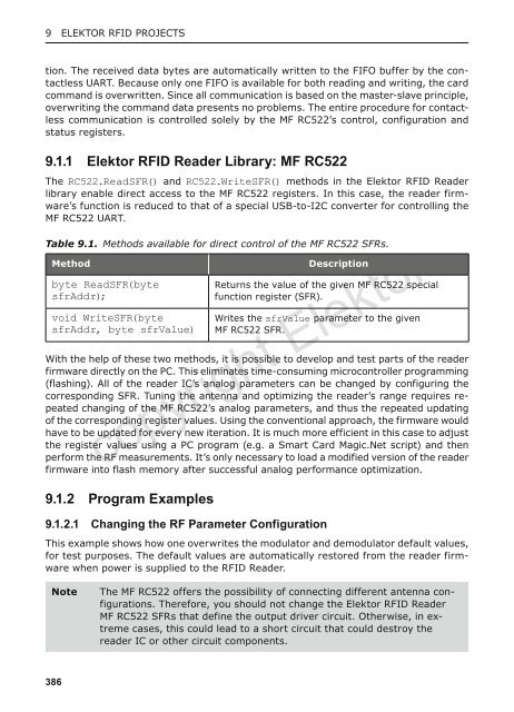
Table 9.1. Methods available for direct control of the MF RC522 SFRs.<br />
Method<br />
byte ReadSFR(byte<br />
sfrAddr);<br />
void WriteSFR(byte<br />
sfrAddr, byte sfrValue)<br />
Description<br />
Returns the value of the given MF RC522 special<br />
function register (SFR).<br />
Writes the sfrValue parameter to the given<br />
MF RC522 SFR.<br />
With the help of these two methods, it is possible to develop and test parts of the reader<br />
firmware directly on the PC. This eliminates time-consuming microcontroller programming<br />
(flashing). All of the reader IC’s analog parameters can be changed by configuring the<br />
corresponding SFR. Tuning the antenna and optimizing the reader’s range requires repeated<br />
changing of the MF RC522’s analog parameters, and thus the repeated updating<br />
of the corresponding register values. Using the conventional approach, the firmware would<br />
have to be updated for every new iteration. It is much more efficient in this case to adjust<br />
the register values using a PC program (e.g. a Smart Card Magic.Net script) and then<br />
perform the RF measurements. It’s only necessary to load a modified version of the reader<br />
firmware into flash memory after successful analog performance optimization.<br />
copyright <strong>Elektor</strong><br />
9.1.2 Program Examples<br />
9.1.2.1 Changing the RF Parameter Configuration<br />
This example shows how one overwrites the modulator and demodulator default values,<br />
for test purposes. The default values are automatically restored from the reader firmware<br />
when power is supplied to the <strong>RFID</strong> Reader.<br />
Note<br />
The MF RC522 offers the possibility of connecting different antenna configurations.<br />
Therefore, you should not change the <strong>Elektor</strong> <strong>RFID</strong> Reader<br />
MF RC522 SFRs that define the output driver circuit. Otherwise, in extreme<br />
cases, this could lead to a short circuit that could destroy the<br />
reader IC or other circuit components.<br />
386


