1. About This Guide - Strand Lighting
1. About This Guide - Strand Lighting
1. About This Guide - Strand Lighting
You also want an ePaper? Increase the reach of your titles
YUMPU automatically turns print PDFs into web optimized ePapers that Google loves.
<strong>Strand</strong> <strong>Lighting</strong> Offices<br />
<strong>Strand</strong> <strong>Lighting</strong> - Dallas<br />
10911 Petal Street<br />
Dallas, TX 75238<br />
Tel: 214-647-7880<br />
Fax: 214-647-8031<br />
<strong>Strand</strong> <strong>Lighting</strong> - New York<br />
267 5th Ave, 4th Floor<br />
New York, NY 10016<br />
Tel: 212-213-8219<br />
Fax: 212-532-2593<br />
<strong>Strand</strong> <strong>Lighting</strong> - Asia Limited<br />
Unit C, 14/F, Roxy Industrial Centre<br />
No. 41-49 Kwai Cheong Road<br />
Kwai Chung, N.T., Hong Kong<br />
Tel: +852 2796 9786<br />
Fax: +852 2798 6545<br />
<strong>Strand</strong> Selecon - Auckland<br />
19-21 Kawana Street<br />
Northcote, Auckland 0627<br />
New Zealand<br />
Tel: +64 9 481 0100<br />
Fax: +64 9 481 0101<br />
<strong>Strand</strong> <strong>Lighting</strong> - Europe<br />
Marssteden 152<br />
Enschede 7547 TD<br />
The Netherlands<br />
Tel: +31 53 4500424<br />
Fax: +31 53 4500425<br />
Website:<br />
www.strandlighting.com<br />
The material in this manual is for information purposes only and is subject to change without notice. <strong>Strand</strong><br />
<strong>Lighting</strong> assumes no responsibility for any errors or omissions which may appear in this manual. For comments and<br />
suggestions regarding corrections and/or updates to this manual, please contact your nearest <strong>Strand</strong> <strong>Lighting</strong> office.<br />
El contenido de este manual es solamente para información y está sujeto a cambios sin previo aviso. <strong>Strand</strong><br />
<strong>Lighting</strong> no asume responsabilidad por errores o omisiones que puedan aparecer. Cualquier comentario, sugerencia<br />
o corrección con respecto a este manual, favor de dirijirlo a la oficina de <strong>Strand</strong> <strong>Lighting</strong> más cercana.<br />
Der Inhalt dieses Handbuches ist nur für Informationszwecke gedacht, Aenderungen sind vorbehalten. <strong>Strand</strong><br />
<strong>Lighting</strong> uebernimmt keine Verantwortung für Fehler oder Irrtuemer, die in diesem Handbuch auftreten. Für<br />
Bemerkungen und Verbesserungsvorschlaege oder Vorschlaege in Bezug auf Korrekturen und/oder<br />
Aktualisierungen in diesem Handbuch, moechten wir Sie bitten, Kontakt mit der naechsten <strong>Strand</strong> <strong>Lighting</strong>-<br />
Niederlassung aufzunehmen.<br />
Le matériel décrit dans ce manuel est pour information seulement et est sujet à changements sans préavis. La<br />
compagnie <strong>Strand</strong> <strong>Lighting</strong> n'assume aucune responsibilité sur toute erreur ou ommission inscrite dans ce manuel.<br />
Pour tous commentaires ou suggestions concernant des corrections et/ou les mises à jour de ce manuel, veuillez s'll<br />
vous plait contacter le bureau de <strong>Strand</strong> <strong>Lighting</strong> le plus proche.<br />
Information contained in this document may not be duplicated in full or in part by any person without prior written<br />
approval of <strong>Strand</strong> <strong>Lighting</strong>. Its sole purpose is to provide the user with conceptual information on the equipment<br />
mentioned. The use of this document for all other purposes is specifically prohibited.<br />
Document Number: 2-450205-010<br />
Version as of: 23 September 2011<br />
Propack Rack Mount Dimmer Installation & Operation <strong>Guide</strong><br />
©2011 Philips Group. All rights reserved.
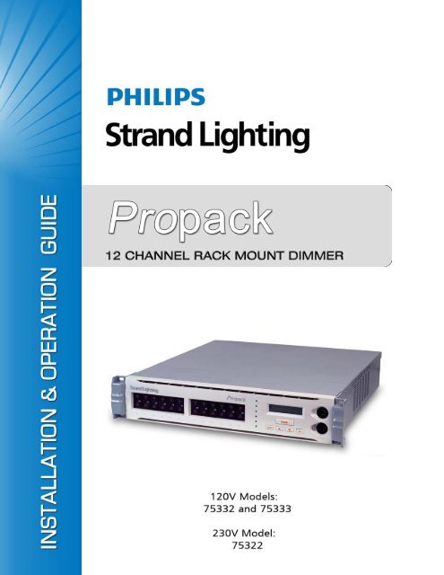
Propack Rack Mount Dimmer<br />
Installation & Operation <strong>Guide</strong><br />
IMPORTANT SAFEGUARDS<br />
When using electrical equipment, basic safety precautions should always be followed including the following:<br />
a. READ AND FOLLOW ALL SAFETY INSTRUCTIONS.<br />
b. Do not use outdoors.<br />
c. Do not mount near gas or electric heaters.<br />
d. Equipment should be mounted in locations and at heights where it will not readily be subjected to<br />
tampering by unauthorized personnel.<br />
e. The use of accessory equipment not recommended by the manufacturer may cause an unsafe<br />
condition.<br />
f. Do not use this equipment for other than intended use.<br />
g. Refer service to qualified personnel.<br />
SAVE THESE INSTRUCTIONS.<br />
WARNING: You must have access to a main circuit breaker or other power disconnect device<br />
before installing any wiring. Be sure that power is disconnected by removing fuses or turning the<br />
main circuit breaker off before installation. Installing the device with power on may expose you to<br />
dangerous voltage and damage the device. A qualified electrician must perform this installation.<br />
WARNING: Refer to National Electrical Code® and local codes for cable specifications. Failure to<br />
use proper cable can result in damage to equipment or danger to persons.<br />
WARNING: <strong>This</strong> equipment is intended for installation in accordance with the National Electric<br />
Code® and local regulations. It is also intended for permanent installation in indoor applications<br />
only. Before any electrical work is performed, disconnect power at the circuit breaker or remove the<br />
fuse to avoid shock or damage to the control. It is recommended that a qualified electrician perform<br />
this installation.<br />
CAUTION: Wire openings MUST have fittings or lining to protect wires/cables from damage. Use<br />
90° C copper wire only! Aluminum wire may not be used.<br />
1
Installation & Operation <strong>Guide</strong><br />
Propack Rack Mount Dimmer<br />
TABLE OF CONTENTS<br />
<strong>Strand</strong> <strong>Lighting</strong> Offices ....................................................................................................... Inside Front Cover<br />
Important Safeguards<br />
Table of Contents<br />
Preface<br />
<strong>About</strong> <strong>This</strong> <strong>Guide</strong> ................................................................................................................................................... 3<br />
Customer Service.................................................................................................................................................... 3<br />
Overview<br />
<strong>About</strong> Propack Dimmers ........................................................................................................................................ 4<br />
120v Models (75332 / 75333) ......................................................................................................................... 4<br />
230v Model (75322)........................................................................................................................................ 4<br />
Installation<br />
General Installation Notes ...................................................................................................................................... 5<br />
Installing 120v Models (75332 / 75333) ................................................................................................................ 5<br />
Mains Power Input Connections (120v).......................................................................................................... 5<br />
Mains Cable Entry (120v) ............................................................................................................................... 6<br />
Mains Cable Termination (120v) .................................................................................................................... 6<br />
Protection (120v)............................................................................................................................................. 6<br />
Power Distribution (120v)............................................................................................................................... 7<br />
Rack Mounting (120v) .................................................................................................................................... 7<br />
Installing 230v Model (75322) ............................................................................................................................... 8<br />
Mains Power Input Connections (230v).......................................................................................................... 8<br />
Mains Cable Entry (230v) ............................................................................................................................... 8<br />
Mains Cable Termination (230v) .................................................................................................................... 9<br />
Protection (230v)............................................................................................................................................. 9<br />
Power Distribution (230v)............................................................................................................................. 10<br />
Rack Mounting (230v) .................................................................................................................................. 10<br />
Input/Output<br />
Control Input......................................................................................................................................................... 11<br />
Dimmer Outputs ................................................................................................................................................... 12<br />
Maintenance and Testing<br />
Overview............................................................................................................................................................... 13<br />
Safety Tests........................................................................................................................................................... 13<br />
Operation<br />
Menu System Overview ....................................................................................................................................... 14<br />
Propack Dimmer Menu Structure......................................................................................................................... 15<br />
Specifications<br />
Propack Dimmer 120v Models (75332 / 75333) .................................................................................................. 18<br />
Propack Dimmer 230v Model (75322)................................................................................................................. 19<br />
2 Table of Contents
Propack Rack Mount Dimmer<br />
Installation & Operation <strong>Guide</strong><br />
PREFACE<br />
<strong>1.</strong> <strong>About</strong> <strong>This</strong> <strong>Guide</strong><br />
The document provides installation and operation instructions for the following Propack Rack Mount Dimming<br />
products:<br />
• 75332 Propack Rack Mount Dimmer, 12x20A, 120V Stage Pin Connector<br />
• 75333 Propack Rack Mount Dimmer, 12x20A, 120V Socapex<br />
• 75322 Propack Rack Mount Dimmer, 12x15A, 230V Socapex<br />
Please read all instructions before installing or using this product. Retain this guide for future reference.<br />
2. Customer Service<br />
Contact <strong>Strand</strong> <strong>Lighting</strong> Customer Service at: 1-800-4STRAND (U.S.) or 1-214-647-7880 (international).<br />
<strong>About</strong> <strong>This</strong> <strong>Guide</strong> 3
Installation & Operation <strong>Guide</strong><br />
Propack Rack Mount Dimmer<br />
OVERVIEW<br />
<strong>1.</strong> <strong>About</strong> Propack Dimmers<br />
Propack 12-Channel Dimmers provide high-density, high-power dimming in a compact 2U rack mount package.<br />
Propack Dimmers feature flat front circuit breakers that provide clear tripped-status indication.<br />
Control is supplied with a <strong>Strand</strong> <strong>Lighting</strong> digital processor. The units accept standard DMX512 multiplexed digital<br />
control input.<br />
120v Models (75332 / 75333)<br />
Front View<br />
Side View<br />
The Propack 120v models contain twelve<br />
2000-watt dimmers that can be connected to<br />
either Socapex or stage pin outputs.<br />
75332 Rear View<br />
75333 Rear View<br />
230v Model (75322)<br />
Front View<br />
Side View<br />
The 230v model contains twelve 3000-watt<br />
dimmers with two Socapex output connections.<br />
Rear View<br />
4 Overview
Propack Rack Mount Dimmer<br />
Installation & Operation <strong>Guide</strong><br />
INSTALLATION<br />
<strong>1.</strong> General Installation Notes<br />
In order to enhance the reliability of the dimmers, it is recommended that they are operated within the following<br />
environmental limits:<br />
• Temperature: 18°C - 25° C<br />
• Relative Humidity: 60% - 80%<br />
• Condensation level: Zero<br />
The dimmers may emit a slight buzzing noise during operation. They should be installed away from areas where such<br />
noise would be undesirable.<br />
Refer to "Specifications" on page 18 for complete technical specifications for each Propack Dimmer model.<br />
2. Installing 120v Models (75332 / 75333)<br />
WARNING! Hazardous voltages are present in Propack Dimmers. Ensure that the mains supply is isolated before<br />
opening the equipment for installation or servicing. Propack Dimmers should be installed and serviced by qualified<br />
personnel only. Propack Dimmers may be mounted together in a rack (for hire or touring purposes).<br />
Mains Power Input Connections (120v)<br />
When installing Propack 120v Dimmers, use the following precautions and guidelines:<br />
• Propack 120v Dimmers require a nominal mains input at 120V 60Hz AC. <strong>This</strong> supply must be three-phase. Separate<br />
Neutral and Ground conductors are required.<br />
• Propack Dimmers must be Grounded.<br />
• The Neutral conductor must have the same (or greater) cross-sectional area as the Phase conductor(s). (SCR dimmers<br />
operate using ‘phase control’. <strong>This</strong> renders the ‘balancing’ of loads across phases - and thus a reduction in<br />
Neutral currents impossible.)<br />
• Propack Dimmers should be connected to their mains supplies via adequately rated cable, together with any associated<br />
plug and socket connectors. For full power operation, the supply must be rated at 80A for three-phase operation.<br />
These ratings may be reduced if the supply protective devices are selected to limit the current drawn to<br />
appropriate limits. Should supply diversity be applied, care is required in the sizing of supply neutral conductors. If<br />
in doubt, please seek advice from your <strong>Strand</strong> <strong>Lighting</strong> representative.<br />
• For safety in operation, each unit must be fed from an appropriately fused supply.<br />
• It is strongly recommended that the mains supply to the Propack Dimmer is taken via a local circuit breaker, so that<br />
the supply may be easily disconnected for plugging and unplugging of load connectors and for service or maintenance.<br />
• All cables, switch gear and protection equipment must be selected and installed in accordance with local electrical<br />
regulations.<br />
General Installation Notes 5
Installation & Operation <strong>Guide</strong><br />
Propack Rack Mount Dimmer<br />
Mains Cable Entry (120v)<br />
The mains input cable will enter the unit via the rear connection panel.<br />
To remove rear connection panel:<br />
Step <strong>1.</strong> At rear of unit, remove four screws (Figure 1).<br />
Step 2. Punch a single hole to accept appropriate cables and strain relief for your installation.<br />
Mains Cable Termination (120v)<br />
Figure 1: Rear Cable Entry Panel<br />
The mains input is connected at a set of screw terminal blocks located inside the unit (at the right-hand side, looking<br />
from the front of the unit). The terminals will accept cables of up to #6 AWG in size.<br />
WARNING! Always connect Ground and Neutral first.<br />
To terminate mains cable:<br />
Step <strong>1.</strong> Loosen all three phase terminals, Neutral and Ground (Figure 2).<br />
Step 2. Place incoming cable inside terminals and tighten securely.<br />
Protection (120v)<br />
Figure 2: Three-Phase Operation at 80A Per Phase<br />
The mains supply to each Propack Dimmer must be protected against external overload. Appropriate circuit breaker<br />
ratings should not exceed 80 Amps for a three-phase supply. If the available mains supply is not capable of providing<br />
the full rated currents, the protection device rating must be reduced accordingly; it will not be possible to use the<br />
dimmers with their maximum rated loads.<br />
Protection systems on the supply to each unit should limit the potential fault current level to 10,000AIC or less.<br />
6 Installation
Propack Rack Mount Dimmer<br />
Installation & Operation <strong>Guide</strong><br />
Power Distribution (120v)<br />
To achieve correct grounding and mains power distribution, it is recommended that all dimmers and lighting control<br />
equipment within the installation draw mains power from one central distribution point. <strong>This</strong> should be as close as<br />
possible to the mains power intake for the site or building. The wiring from the distribution point to the lighting<br />
equipment should ideally be used for supplying power to the lighting equipment alone, and not to other appliances or<br />
equipment.<br />
WARNING! Propack Dimmers must be properly Grounded, both for safety and to ensure correct operation.<br />
It is essential that all Ground connections within the overall installation are at comparable potentials. If this is not the<br />
case, circulating currents may be generated in signal earth connections, possibly leading to fluctuating light levels and<br />
(in some extreme cases) damage to wiring or equipment. If in doubt as to the nature of your local electrical supply<br />
arrangements, please seek advice from a <strong>Strand</strong> <strong>Lighting</strong> representative or an electrical contractor.<br />
Rack Mounting (120v)<br />
The Propack Dimmer is designed for rack mounting. Care should be taken to mount the unit securely in an equipment<br />
rack designed to hold equipment of this type.<br />
To prevent overheating of rack-mounted dimmers when in use, a fan - or set of fans - should be fitted to the top of the<br />
equipment rack, such that air is extracted upwards. To ensure adequate cooling, the fan(s) should provide an airflow<br />
of about 16 liters per second across the top of each unit.<br />
A gap of 1U (<strong>1.</strong>75 inches / 44.45 mm) is required between adjacent pairs of dimmer racks. Leave a rear ventilation<br />
clearance of 4 inches. Due to the weight of the unit, rack side supports are recommended, but care must be taken to<br />
ensure that these do not obstruct ventilation.<br />
CAUTION: Additional forced ventilation may be advised if racks are mounted within a flight case or similar closely<br />
constraining enclosure.<br />
Installing 120v Models (75332 / 75333) 7
Installation & Operation <strong>Guide</strong><br />
Propack Rack Mount Dimmer<br />
3. Installing 230v Model (75322)<br />
WARNING! Hazardous voltages are present in Propack Dimmers. Ensure that the mains supply is isolated before<br />
opening the equipment for installation or servicing. Propack Dimmers should be installed and serviced by qualified<br />
personnel only. Propack Dimmers may be mounted together in a rack (for hire or touring purposes).<br />
Mains Power Input Connections (230v)<br />
When installing Propack 230v Dimmers, use the following precautions and guidelines:<br />
• Propack 230v Dimmers require a nominal mains input at 230V 50Hz AC. <strong>This</strong> supply may be either single or<br />
three-phase (star only), depending on the method of connection. In either case, separate Neutral and Earth conductors<br />
are required.<br />
• Propack Dimmers must be Earthed.<br />
• Propack Dimmers are designed such that Earth leakage currents are minimized, allowing their use on mains power<br />
supplies protected by 30mA Residual Current Devices. However, utilizing RCD protection in dimming installations<br />
may present problems. For specific advice please contact your <strong>Strand</strong> <strong>Lighting</strong> representative.<br />
• The Neutral conductor must have the same (or greater) cross-sectional area as the Phase conductor(s). (Triac and<br />
thyristor dimmers operate using ‘phase control’. <strong>This</strong> renders the ‘balancing’ of loads across phases - and thus a<br />
reduction in Neutral currents impossible.)<br />
• Propack Dimmers should be connected to their mains supplies via adequately rated cable, together with any associated<br />
plug and socket connectors. For full power operation, the supply must be rated at 125A for single phase<br />
operation, 63A for three-phase operation. These ratings may be reduced if the supply protective devices are<br />
selected to limit the current drawn to appropriate limits. Should supply diversity be applied, care is required in the<br />
sizing of supply Neutral conductors. If in doubt, please seek advice from your <strong>Strand</strong> <strong>Lighting</strong> representative.<br />
• For safety in operation, each unit must be fed from an appropriately fused supply.<br />
• It is strongly recommended that the mains supply to the Propack Dimmer is taken via a local isolating switch, so<br />
that the supply may be easily disconnected for plugging and unplugging of load connectors and for service or<br />
maintenance.<br />
• All cables, switch gear and protection equipment must be selected and installed in accordance with local electrical<br />
regulations.<br />
Mains Cable Entry (230v)<br />
The mains input cable will enter the unit via the rear connection panel.<br />
To remove rear connection panel:<br />
Step <strong>1.</strong> At rear of unit, remove four screws (Figure 3).<br />
Step 2. Punch a single hole to accept appropriate cables and strain relief for your installation.<br />
Figure 3: Rear Cable Entry Panel<br />
8 Installation
Propack Rack Mount Dimmer<br />
Installation & Operation <strong>Guide</strong><br />
Mains Cable Termination (230v)<br />
The mains input is connected at a set of screw terminal blocks located inside the unit (at the right-hand side, looking<br />
from the front of the unit). The terminals will accept cables of up to 16 mm2 in size. If it is required to connect a<br />
Propack Dimmer to a single phase supply, the link bar supplied with the unit should be used to join the three-phase<br />
terminals together as shown in the figure below.<br />
WARNING! Do NOT fit the link bar when the unit is connected to a three-phase supply.<br />
To terminate mains cable:<br />
Step <strong>1.</strong> Loosen all three phase terminals.<br />
Step 2. Place incoming cable inside terminals and tighten securely.<br />
Figure 4: Three-Phase Operation at 80A per phase<br />
Protection (230v)<br />
Figure 5: Single Phase Operation 230v<br />
The mains supply to each Propack Dimmer must be protected against external overload. Appropriate fuse or circuit<br />
breaker ratings are 63A for a three-phase supply. If the available mains supply is not capable of providing the full<br />
rated currents, the protection device rating must be reduced accordingly; it will not be possible to use the dimmers<br />
with their maximum rated loads.<br />
Protection systems on the supply to each unit should limit the potential fault current level to 1500A or less.<br />
Installing 230v Model (75322) 9
Installation & Operation <strong>Guide</strong><br />
Propack Rack Mount Dimmer<br />
Power Distribution (230v)<br />
To achieve correct Earthing and mains power distribution, it is recommended that all dimmers and lighting control<br />
equipment within the installation draw mains power from one central distribution point. <strong>This</strong> should be as close as<br />
possible to the mains power intake for the site or building. The wiring from the distribution point to the lighting<br />
equipment should ideally be used for supplying power to the lighting equipment alone, and not to other appliances or<br />
equipment.<br />
WARNING! Propack Dimmers must be properly Earthed, both for safety and to ensure correct operation.<br />
It is essential that all Earth connections within the overall installation are at comparable potentials. If this is not the<br />
case, circulating currents may be generated in signal earth connections, possibly leading to fluctuating light levels and<br />
(in some extreme cases) damage to wiring or equipment.<br />
Care should be taken when differing electrical supplies (for example local generation for dimmers, public mains for<br />
control console) are in use or internal mains power distribution is TN-C (combined neutral & earth conductors). If in<br />
doubt as to the nature of your local electrical supply arrangements, please seek advice from a <strong>Strand</strong> <strong>Lighting</strong><br />
representative or an electrical contractor.<br />
Rack Mounting (230v)<br />
The Propack Dimmer is designed for rack mounting. Care should be taken to mount the unit securely in an equipment<br />
rack designed to hold equipment of this type.<br />
To prevent overheating of rack-mounted dimmers when in use, a fan - or set of fans - should be fitted to the top of the<br />
equipment rack, such that air is extracted upwards. To ensure adequate cooling, the fan(s) should provide an airflow<br />
of about 16 liters per second across the top of each unit.<br />
A gap of 1U (44.5mm) is required between adjacent pairs of dimmer racks. Leave a rear ventilation clearance of<br />
100mm. Due to the weight of the unit, rack side supports are recommended, but care must be taken to ensure that<br />
these do not obstruct ventilation.<br />
CAUTION: Additional forced ventilation may be advised if racks are mounted within a flight case or similar closely<br />
constraining enclosure.<br />
10 Installation
Propack Rack Mount Dimmer<br />
Installation & Operation <strong>Guide</strong><br />
INPUT/OUTPUT<br />
<strong>1.</strong> Control Input<br />
Propack Dimmers accept DMX512 control inputs.<br />
DMX512<br />
The DMX512 input will accept a multiplexed digital control signal which conforms to USITT specification DMX512<br />
(1990). Details of this specification are available from USITT.<br />
The DMX512 control input is via a five-pin male XLR type connector. Pin connections are shown in Figure 6 below.<br />
A five-pin female XLR connector is also fitted to allow a series of Propack Dimmers (or other DMX512 equipment)<br />
to be daisy-chained together.<br />
Control 0v<br />
Not Used<br />
DMX-<br />
DMX512 Input Connector<br />
DMX+<br />
Figure 6: DMX512 In Pin Outs<br />
Control Input 11
Installation & Operation <strong>Guide</strong><br />
Propack Rack Mount Dimmer<br />
2. Dimmer Outputs<br />
Dimmer output connections are by means of receptacle/socket outlets located at the rear panel of the Propack<br />
Dimmer.<br />
<strong>Guide</strong>lines:<br />
• When operating from a three-phase supply, dimmers 1, 2, 3 & 4 are connected to phase 1, dimmers 5, 6, 7 & 8 to<br />
phase 2, and dimmers 9, 10, 11 & 12 to phase 3.<br />
• Plugs and connectors used for dimmer output connections must be of the correct type to match the socket outlets.<br />
• It is important that plugs are wired correctly. Figure 7 shows the various types of socket outlets fitted to Propack<br />
Dimmers.<br />
Socapex<br />
Stage Pin (120v Only)<br />
Figure 7: Socket Outlet Types<br />
12 Input/Output
Propack Rack Mount Dimmer<br />
Installation & Operation <strong>Guide</strong><br />
MAINTENANCE AND TESTING<br />
<strong>1.</strong> Overview<br />
Propack Dimmers do not require routine maintenance other than external cleaning. However, in common with all<br />
electrical equipment, they should be periodically checked to ensure that they remain in good condition. Any repairs or<br />
maintenance to the internal electronics or other circuitry should be carried out only by authorized <strong>Strand</strong> <strong>Lighting</strong><br />
Service Personnel or approved Service Providers.<br />
2. Safety Tests<br />
Propack Dimmers are subjected to safety inspections and tests prior to shipment from the <strong>Strand</strong> <strong>Lighting</strong> factory.<br />
If, as part of routine maintenance, the units are to be subjected to electrical safety tests applied using a standard<br />
Portable Appliance Tester, the following points should be observed:<br />
• The nature of the electronic dimmer circuits means that an "insulation test" using a voltage in the order of 500V<br />
will give a result of approximately <strong>1.</strong>7MO. Although this may appear as a test failure, the apparently low resistance<br />
is normal for these units and is not due to failing insulation. User safety is not at risk.<br />
CAUTION: A high voltage "Flash" test must not be applied to a Propack dimmer pack.<br />
CAUTION: A high current Earth/Ground continuity test must not be applied to the signal ground pins of the control<br />
input connector(s).<br />
Overview 13
Installation & Operation <strong>Guide</strong><br />
Propack Rack Mount Dimmer<br />
OPERATION<br />
<strong>1.</strong> Menu System Overview<br />
LCD Menu Display -<br />
2 line LCD display. At initial start up or<br />
when not in menu selection mode,<br />
displays unit’s current DMX512 address.<br />
PROpack - DMX:-<br />
HOME Button -<br />
<strong>This</strong> button returns to<br />
the main menu.<br />
OK Button -<br />
<strong>This</strong> button selects and is<br />
used to confirm user’s<br />
selections.<br />
BACK Button -<br />
Pressing this button takes users<br />
back one level (back to previous<br />
menu item or selection).<br />
UP and DOWN Arrow Buttons -<br />
These buttons scroll through menu<br />
selections / options.<br />
Figure 8: Menu Display and Buttons<br />
14 Operation
Propack Rack Mount Dimmer<br />
Installation & Operation <strong>Guide</strong><br />
2. Propack Dimmer Menu Structure<br />
Setting Menu<br />
• Set Level<br />
• Address<br />
• Curves<br />
• Preset<br />
• Preset Call<br />
• Minimum Output<br />
• Maximum Output<br />
• Set Up<br />
• Information<br />
Set Level<br />
Sub Menu Options Comments<br />
DIM X (1 thru 12), All, Even, or Odd<br />
Address<br />
0 to 99%, FL (full)<br />
Manually sets the level for each<br />
dimmer, only EVEN numbered<br />
dimmers, ODD numbered dimmers,<br />
or ALL dimmers<br />
Sub Menu Options Comments<br />
Start Address DMX XXX (1 thru 512)<br />
Sets the starting DMX address for the<br />
Propack dimmer module<br />
Patch<br />
DIM X (1 thru 12) to DMX XXX (1 thru<br />
512)<br />
Sets (patches) the DMX address for<br />
the twelve dimmers in the Propack<br />
dimmer module<br />
Curves<br />
Sub Menu Options Comments<br />
Square (Square Law dimming<br />
operation)<br />
DIM X (1 thru 12), or ALL (all<br />
dimmers)<br />
S-Curve (phase /sinewave dimming<br />
operation)<br />
Non-Dim (switching ON/OFF<br />
operation only)<br />
Low-Cut (lower end of waveform cut<br />
off)<br />
Linear (linear response dimming)<br />
Users can set the dimming (or nondim)<br />
operation of each individual<br />
dimmer or ALL dimmers.<br />
Preset<br />
Sub Menu Options Comments<br />
Level Set<br />
Preset X (1 thru 40)<br />
Snapshot Preset X (1 thru 40) or ALL<br />
Remote Snap Shot<br />
Users can set each dimmers level for<br />
40 user-definable Presets. Dimmers<br />
can be set from 0 to 99% or FL (full<br />
on)<br />
Snapshots current dimmers levels to<br />
a specific Preset number or to ALL<br />
Presets.<br />
Snapshots incoming (active - from<br />
external source) DMX512 data stream<br />
to a specific Preset number.<br />
Continued next page<br />
Propack Dimmer Menu Structure 15
Installation & Operation <strong>Guide</strong><br />
Propack Rack Mount Dimmer<br />
Propack Dimmer Menu Structure (continued)<br />
Continued from previous page<br />
Preset Call<br />
Sub Menu Options Comments<br />
Local Preset X (1 thru 40)<br />
Remote<br />
Minimum Level<br />
Disable, Enable LTP, or Enable HTP<br />
Manually (from dimmer menu system)<br />
recalls a preprogrammed Preset.<br />
Once desired preset number is<br />
display on the LCD screen, hit [OK] to<br />
select and activate preset.<br />
Sets remote DMX512 devices access<br />
to Propack dimmer module Presets.<br />
Choices are Disable (no access),<br />
Enable LTP (commands from remote<br />
device takes lowest precedence) or<br />
Enable HTP (commands from remote<br />
device takes highest precedence)<br />
Sub Menu Options Comments<br />
DIM X (1 thru 12), Even, Odd, or All<br />
Maximum Level<br />
0 to 99% or FL (full)<br />
Sets the minimum output level for<br />
each dimmer, only EVEN numbered<br />
dimmers, ODD numbered dimmers,<br />
or ALL dimmers.<br />
Sub Menu Options Comments<br />
DIM X (1 thru 12), Even, Odd, or All<br />
Set Up<br />
0 to 99% or FL (full)<br />
Sets the maximum output level for<br />
each dimmer, only EVEN numbered<br />
dimmers, ODD numbered dimmers,<br />
or ALL dimmers.<br />
Sub Menu Options Comments<br />
DMX Fail (DMX512 signal failure)<br />
Ventilation (Propack dimming module<br />
fan operational modes)<br />
Last Hold<br />
Off<br />
Off After X min. (0 to 90 minutes in 1<br />
minute increments)<br />
Preset X (1 thru 40)<br />
On with DMX<br />
Silence<br />
Fans On<br />
Normal<br />
Sets Propack dimmer module<br />
operation in the event that DMX512 is<br />
removed or fails. Choices are hold<br />
last DMX values, turn dimmers off,<br />
hold last DMX values for a set number<br />
of minutes - then turn off dimmers, or<br />
go to a defined Preset.<br />
Turns on Propack dimmer module<br />
fans when DMX512 is present.<br />
No fan operation.Fans will not turn on.<br />
Note: this setting should only be used<br />
if the dimmer module is cooled<br />
externally (by another cooling<br />
source).<br />
Manually turns on Propack dimmer<br />
module fans. Note: fans will not turn<br />
off until setting is manually changed.<br />
Normal operational setting. Fans will<br />
only turn on when the upper<br />
operational temperature threshold is<br />
surpassed. Fans will turn off once<br />
below this threshold.<br />
Continued next page<br />
16 Operation
Propack Rack Mount Dimmer<br />
Installation & Operation <strong>Guide</strong><br />
Propack Dimmer Menu Structure (continued)<br />
Continued from previous page<br />
Information<br />
Sub Menu Options Comments<br />
Software Version<br />
Temperature<br />
N/A<br />
L = X C / R = X C<br />
Hit [OK] to view the unit’s current<br />
software version<br />
Displays the temperature (in degrees<br />
C) for the left (L) and light (R) banks of<br />
dimmers in the Propack dimming<br />
module. Hit [OK] to view the unit’s<br />
current temperatures.<br />
Propack Dimmer Menu Structure 17
Installation & Operation <strong>Guide</strong><br />
Propack Rack Mount Dimmer<br />
SPECIFICATIONS<br />
<strong>1.</strong> Propack Dimmer 120v Models (75332 / 75333)<br />
Technical Specifications:<br />
Supply Voltage: 100 - 120VAC, 3 phase<br />
Output Voltage: 100 - 120VAC, 60 Hz<br />
No. of Dimmers/Unit: 12<br />
Load per Dimmer: 2.0kW (20A max.)<br />
Capacity per Unit: 24kW (max)<br />
Load Connections:<br />
- 75332: Stage Pin (12 each)<br />
- 75333: 2 x Socapex<br />
Mechanical Data:<br />
Weight: 34 lbs (approx.)<br />
Dimensions: 3.75 (H) x 19 (W) x 18 (D) in<br />
DMX512 Connections: DMX512 In / Out (thru)<br />
Environmental Data:<br />
Temperature: 32 to 99°F<br />
Humidity Range: 60 to 90% Non-condensing<br />
Front View<br />
Side View<br />
75332 Rear View<br />
75333 Rear View<br />
18 Specifications
Propack Rack Mount Dimmer<br />
Installation & Operation <strong>Guide</strong><br />
2. Propack Dimmer 230v Model (75322)<br />
Technical Specifications:<br />
Supply Voltage: 200 - 260VAC<br />
Output Voltage: 200 - 260VAC, 50 - 60 Hz<br />
No. of Dimmers/Unit: 12<br />
Load per Dimmer: 3.0kW (15A max.)<br />
Capacity per Unit: 36kW (max.)<br />
Load Connections: Socapex (2 each)<br />
Mechanical Data:<br />
Weight: 15.3 kg (approx.)<br />
Dimensions: 89 (2U) (H) x 483 (W) x 460 (D) mm<br />
DMX512 Connections: DMX512 In / Out (thru)<br />
Environmental Data:<br />
Temperature: 0 to 37°F<br />
Humidity Range: 60 to 90% Non-condensing<br />
483 mm<br />
447 mm<br />
89 mm<br />
Front View<br />
Side View<br />
432 mm<br />
Rear View<br />
Propack Dimmer 230v Model (75322) 19
Installation & Operation <strong>Guide</strong><br />
Propack Rack Mount Dimmer<br />
Notes<br />
20 Specifications
Propack Rack Mount Dimmer<br />
Installation & Operation <strong>Guide</strong><br />
Notes<br />
Propack Dimmer 230v Model (75322) 21
2-450205-010


