London Kitchen Sinks Installation Instructions - Porcher
London Kitchen Sinks Installation Instructions - Porcher
London Kitchen Sinks Installation Instructions - Porcher

Create successful ePaper yourself
Turn your PDF publications into a flip-book with our unique Google optimized e-Paper software.
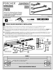
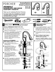
INSTALLATION INSTRUCTIONS<br />
CARE AND MAINTENANCE<br />
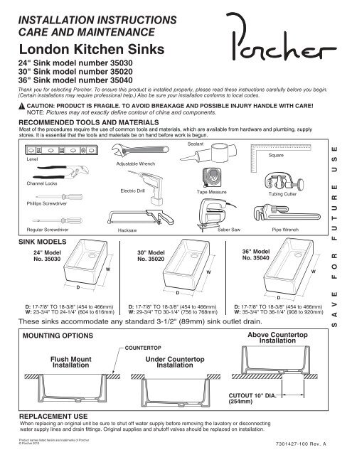
<strong>London</strong> <strong>Kitchen</strong> <strong>Sinks</strong><br />
24" Sink model number 35030<br />
30" Sink model number 35020<br />
36" Sink model number 35040<br />
Thank you for selecting <strong>Porcher</strong>. To ensure this product is installed properly, please read these instructions carefully before you begin.<br />
(Certain installations may require professional help.) Also be sure your installation conforms to local codes.<br />
!<br />
CAUTION: PRODUCT IS FRAGILE. TO AVOID BREAKAGE AND POSSIBLE INJURY HANDLE WITH CARE!<br />
NOTE: Pictures may not exactly define contour of china and components.<br />
RECOMMENDED TOOLS AND MATERIALS<br />
Most of the procedures require the use of common tools and materials, which are available from hardware and plumbing, supply<br />
stores. It is essential that the tools and materials be on hand before work is begun.<br />
Level<br />
Channel Locks<br />
Phillips Screwdriver<br />
Regular Screwdriver<br />
SINK MODELS<br />
24" Model<br />
No. 35030<br />
D: 17-7/8" TO 18-3/8" (454 to 466mm)<br />
W: 23-3/4" TO 24-1/4" (604 to 616mm)<br />
D<br />
W<br />
Adjustable Wrench<br />
Electric Drill<br />
Hacksaw<br />
30" Model<br />
No. 35020<br />
Sealant<br />
10'<br />
Tape Measure<br />
D: 17-7/8" TO 18-3/8" (454 to 466mm)<br />
W: 29-3/4" TO 30-1/4" (756 to 768mm)<br />
Saber Saw<br />
1 2 3 4 5 6 7 8 9 10 11<br />
1 2 3 4 5 6 7 8 9 10 11 12 13 14 15 16 17 18 19 20 21 22 23 24<br />
36" Model<br />
No. 35040<br />
These sinks accommodate any standard 3-1/2" (89mm) sink outlet drain.<br />
D<br />
W<br />
Square<br />
Tubing Cutter<br />
Pipe Wrench<br />
D<br />
D: 17-7/8" TO 18-3/8" (454 to 466mm)<br />
W: 35-3/4" TO 36-1/4" (908 to 920mm)<br />
W<br />
S A V E F O R F U T U R E U S E<br />
MOUNTING OPTIONS<br />
Flush Mount<br />
<strong>Installation</strong><br />
COUNTERTOP<br />
Under Countertop<br />
<strong>Installation</strong><br />
Above Countertop<br />
<strong>Installation</strong><br />
CUTOUT 10" DIA.<br />
(254mm)<br />
REPLACEMENT USE<br />
When replacing an original unit be sure to shut off water supply before removing the lavatory or disconnecting<br />
water supply lines and drain fittings. Original supplies and shutoff valves should be replaced on installation.<br />
Product names listed herein are trademarks of <strong>Porcher</strong><br />
© <strong>Porcher</strong> 2010<br />
7301427-100 Rev. A
INSTALLATION PROCEDURES<br />
Typical installation includes cabinet support preparation, installation of faucet and pop-up drain, connection of flexible<br />
water supply lines, attachment of sink to cabinet, sizing and installation of drain, supplies to house water system.<br />
Sink Mounting Provisions – Whether the sink is used for replacement or new installation, the cabinet area beneath<br />
the sink must be reinforced to provide sufficient support. The wood support frame for the sink must support 400<br />
pounds (approximate weight of sink when full and a garbage disposal installed).<br />
CABINET SUPPORT PREPERATION<br />
Important Note:<br />
This installation assumes the use of a custom cabinet and countertop design. It is not designed for use with standard<br />
base cabinets or standard countertops. <strong>Installation</strong> must be performed by a professional cabinet maker and shall be<br />
in accordance with all local plumbing and building codes requirements.<br />
FLUSH MOUNT or UNDER COUNTERTOP INSTALLATIONS<br />
(See page 7 for above counter top installation)<br />
1<br />
DETERMINE MOUNTING OPTIONS<br />
Determine if the sink will be flush mounted or under countertop mounted. Next measure the actual size of the sink<br />
being installed to determine cabinet opening dimensions and support frame location. The cabinet opening should<br />
equal the maximum dimensions of the sink to ensure a minimum gap between the sink apron and the cabinet.<br />
Support frame location is determined by type of sink installation being performed.<br />
TOP SURFACE OF SINK & COUNTERTOP<br />
ENSURE LEVEL BEFORE SECURING<br />
H & C SUPPIES<br />
FRAME<br />
RUNNING FRONT<br />
TYP. BOTH SIDES<br />
SINK<br />
COUNTERTOP<br />
FLUSH MOUNT<br />
INSTALLATION<br />
SHOWN<br />
SUPPORT<br />
NOMINAL SIZE<br />
FRAME<br />
RUNNING SIDE<br />
TYP. FRONT & REAR<br />
- 2 -<br />
7301427-100 Rev. A
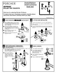
2<br />
SUPPORT FRAME<br />
Construct a support frame to fit inside the cabinet opening. Ensure you provide proper clearance for faucet,<br />
water supply lines, drain assembly, garbage disposal mounting system and the structural parts of the cabinet.<br />
Flush Mount <strong>Installation</strong> Note:<br />
Ensure to install the support frame so that the top rim of the sink, (when placed within the frame), will be level<br />
and flush with the top surface of the countertop, (when countertop is installed). See diagram 2A below.<br />
Under Countertop Mount <strong>Installation</strong> Note:<br />
Ensure to install the support frame so that the top rim of the sink (when placed within the frame) is level and<br />
flush with top surface of the cabinet. (Top of sink rim must be flush and level with top of cabinet in order to<br />
obtain proper contact with the underside of the countertop). See diagram 2B below.<br />
FRAME MEMBERS<br />
RUNNING FRONT<br />
TYP. BOTH SIDES<br />
SINK<br />
COUNTERTOP<br />
SINK TO BE LEVEL AND FLUSH<br />
WITH THE TOP SURFACE OF<br />
THE COUNTERTOP<br />
2A<br />
FLUSH MOUNT<br />
INSTALLATION<br />
SINK SUPPORT FRAME<br />
FRAME MEMBERS<br />
RUNNING SIDE TO SIDE<br />
TYP. FRONT & REAR<br />
SINK<br />
TOP OF SINK RIM MUST<br />
BE FLUSH AND LEVEL<br />
WITH TOP OF CABINET<br />
2B<br />
UNDER COUNTERTOP<br />
MOUNT INSTALLATION<br />
TOP OF CABINET<br />
- 3 -<br />
7301427-100 Rev. A
3 SINK INSTALLATION<br />
CAUTION: <strong>Sinks</strong> are extremely heavy.<br />
For personal safety, always use extra personal for installation.<br />
STEP 1. Carefully set the sink within the support frame and position in center of cabinet opening. If flush mounted<br />
ensure that the sink top rim surface is level and flush with the countertop top surface, (when countertop is installed).<br />
If under countertop mounted ensure that the sink top rim is level and flush with cabinet top surface. Check<br />
clearance around sink apron and ensure sink is<br />
centered within cabinet opening. Ensure sink base is making proper contact with support frame. Adjust or shim as<br />
needed to obtain proper sink position and fit.<br />
STEP 2. Carefully remove sink and place a thin layer of sealant around top edge of support frame where the sink<br />
and frame will make contact. Then replace sink back into position. See diagram below.<br />
PLACE A THIN LAYER OF SEALANT AROUND<br />
TOP EDGE OF SUPPORT FRAME<br />
4A<br />
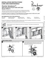
Flush Mount <strong>Installation</strong><br />
Using carpenters square carefully measure and mark the location of the cutout opening in the countertop.<br />
Flush mount cutout opening is determined from the actual sink size. The cutout opening should equal the<br />
maximum dimensions of the sink to ensure a minimum gap between the sink and the countertop opening.<br />
Note: Check dimensions on first page as a reference and measure the sink being installed.<br />
ACTUAL SINK<br />
DIMENSIONS<br />
COUNTERTOP<br />
CUTOUT DIMENSIONS<br />
ACTUAL SINK DIMENSIONS<br />
COUNTERTOP CUTOUT DIMENSIONS<br />
- 4 -<br />
7301427-100 Rev. A
4B Under Countertop <strong>Installation</strong><br />
Under countertop mount cutout opening is determined by cabinet opening and should be 1" (2.5mm ) smaller<br />
than the cabinet opening on the sides and from back of sink apron. Carefully cut out the countertop opening,<br />
opening must be adequately finished and sealed to prevent damage from water absorption.<br />
Note: Check dimensions on first page as a reference and measure the sink being installed.<br />
1" (25mm)<br />
COUNTERTOP<br />
CUTOUT<br />
DIMENSION<br />
ACTUAL SINK<br />
DIMENSIONS<br />
1" (25mm)<br />
COUNTERTOP<br />
1" (25mm)<br />
CUTOUT DIMENSION<br />
CABINET OPENING DIMENSION<br />
5A APPLY SEALANT<br />
For Flush Mount <strong>Sinks</strong>: Carefully wipe clean<br />
the sink apron and top rim free from all debris.<br />
Ensure that the surface on underside of<br />
countertop and around the countertop cutout<br />
opening is smooth and free of debris. Flush<br />
mount installation requires a generous bead of<br />
sealant around the sink apron where sink and<br />
countertop will meet.<br />
APPLY SEALANT<br />
THREE SIDES<br />
TOP OF CABINET<br />
- 5 -<br />
7301427-100 Rev. A
5B<br />
APPLY SEALANT<br />
For Under Countertop <strong>Sinks</strong>: Carefully wipe<br />
clean the sink apron and top rim free from all<br />
debris. Ensure that the surface on underside<br />
of countertop cutout opening is smooth and<br />
free of debris. Under countertop installation<br />
requires a generous bead of sealant around<br />
the sink top rim where sink and countertop<br />
underside will make contact.<br />
APPLY SEALANT<br />
ON TOP THREE<br />
SIDES OF RIM<br />
TOP OF CABINET<br />
6<br />
INSTALL COUNTERTOP<br />
Carefully position and install the countertop. Ensure the sealant provides a complete seal between the sink and<br />
the countertop surface. Fill any voids and wipe excess away with soft damp cloth.<br />
7<br />
ASSEMBLE AND INSTALL P-TRAP AND DRAIN CONNECTIONS<br />
Assemble and install P-trap drain connections in accordance<br />
with manufacturer’s instructions. Connect trap to drain<br />
assembly hand tight to check alignment. It may be<br />
necessary to cut off part of the tailpiece (area "B") or part of<br />
the horizontal leg of the trap (area "C"). Secure joints for<br />
watertight assembly.<br />
C<br />
B<br />
8<br />
INSTALL FAUCET<br />
Carefully locate and install faucet to countertop in accordance with manufacturer’s instructions.<br />
Ensure you provide adequate clearance for supply lines and faucet operation.<br />
Connect supply lines to shutoff valves. Turn on water supply valves and water-test installation.<br />
- 6 -<br />
7301427-100 Rev. A
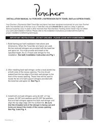
ABOVE COUNTERTOP INSTALLATION<br />
I SINK INSTALLATION<br />
Step 1. Position sink in place. Mark the center of the drain on the countertop as a guide for the<br />
installation location, allowing sufficient distance to the finished wall based on faucets chosen (Deck mount<br />
or Wall mount).<br />
Step 2. Mark a 10 inch (254 mm) cut-out diameter on the counter centered on the mark. Drill a clearance<br />
hole inside the perimeter line and then cut opening around the perimeter. Use appropriate cutting tool for<br />
countertop material.<br />
Step 3. Place a layer of sealant around the bottom edge of the sink where the sink and counter will make<br />
contact. Then replace sink back into position. You can also carefully mark the perimeter of the sink on the<br />
counter and apply the sealant on the counter instead of applying it on the bottom edge of the sink. Fill any<br />
voids and wide excess away with soft damp cloth.<br />
X"<br />
FINISHED WALL<br />
SINK<br />
CUTOUT<br />
10" (254mm) DIA.<br />
IN COUNTERTOP<br />
SINK<br />
OUTLINE<br />
SEALANT<br />
OUTLINE OF SINK<br />
Y"<br />
COUNTERTOP<br />
10" DIA. 254mm)<br />
CUTOUT<br />
II<br />
ASSEMBLE AND INSTALL P-TRAP AND DRAIN CONNECTIONS<br />
Assemble and install P-trap drain connections in accordance with<br />
manufacturer’s instructions. Connect trap to drain assembly hand<br />
tight to check alignment. It may be necessary to cut off part of the<br />
tailpiece (area "B") or part of the horizontal leg of the trap (area<br />
"C"). Secure joints for watertight assembly.<br />
C<br />
B<br />
III<br />
INSTALL FAUCET<br />
Carefully locate and install faucet to countertop in accordance with manufacturer’s instructions.<br />
Ensure you provide adequate clearance for supply lines and faucet operation.<br />
Connect supply lines to shutoff valves. Turn on water supply valves and water-test installation.<br />
- 7 -<br />
7301427-100 Rev. A
CARE AND MAINTENANCE<br />
Do not use harsh abrasives or caustic cleaners to clean fixture surfaces. A mild detergent, warm water, and<br />
a soft cloth will remove normal dirt and soap accumulations from fittings and surfaces. Rinse throughly after<br />
cleaning and polish with a soft dry cloth to restore original luster of material.<br />
FIXTURE LIMITED WARRANTY<br />
If inspection of this <strong>Porcher</strong> plumbing product, within one year after its initial purchase, confirms that it is<br />
defective in materials or workmanship, <strong>Porcher</strong> will repair or, at its option, exchange the product for a similar<br />
model. Variations in shading, veining, and texture which may result from natural characteristics of stone and<br />
as such are not defects and are not covered by this warranty.<br />
This limited warranty does not apply to local building code compliance. Since local building codes vary<br />
considerably, the purchaser of this product should check with a local building or plumbing contractor to<br />
insure local code compliance before installation. This warranty shall be void if the product has been moved<br />
from its initial place of installation; if it has been subjected to faulty maintenance, abuse, misuse, accident or<br />
other damages; if it was not installed in accordance with <strong>Porcher</strong>’s instructions; or if it has been modified in a<br />
manner inconsitent with the product as shipped by <strong>Porcher</strong>.<br />
<strong>Porcher</strong>’s option to repair or exchange the product under this warranty does not cover any labor or other<br />
costs of removal or installation. <strong>Porcher</strong> will not be responsible for any other incidental or<br />
consequential damages attributable to a product defect or to the repair or exchange of a defective<br />
product, all of which are expressly excluded from this warranty. This limited warranty does not cover<br />
any liability for consequential or incidental damage, all of which are hereby expressly disclaimed, or the<br />
extension beyond duration of this limited warranty of any implied warranties, including those of<br />
merchantability or fitness for an intended purpose. (Some state or provinces do not allow the exclusion or<br />
limitation of implied warranties, so this exclusion may not apply to you).<br />
This warranty gives you specific legal rights. You may have other statutory rights that vary from state to state<br />
or from province to province, in which case this warranty does not affect such statutory rights.<br />
For service under these warranties, it is suggested that a claim be made through the contractor or dealer from<br />
or through whom the product was purchased, or that a service request (including a description of the product<br />
model and of the defect) be sent to the following address:<br />
In the United States:<br />
<strong>Porcher</strong> Inc.<br />
P.O. Box 6820<br />
Piscataway, New Jersey 08855<br />
Attention: Director of Consumer Affairs<br />
For residents of the United States, warranty<br />
information may also be obtained by calling the<br />
following toll free number: (800) 359-3261<br />
www.porcher-us.com<br />
In Canada:<br />
<strong>Porcher</strong><br />
5900 Avebury Rd.<br />
Mississauga, Ontario<br />
Canada L5R 3M3<br />
Toll Free: (800) 387-0369<br />
In Mexico:<br />
<strong>Porcher</strong><br />
Planta Santa Clara<br />
Via Morelos #330<br />
Santa Clara Coatitla<br />
de Morelos 55540<br />
Estado de Mexico, Mexico<br />
- 8 -<br />
7301427-100 Rev. A