Development of electroplated magnetic materials for MEMS
Development of electroplated magnetic materials for MEMS
Development of electroplated magnetic materials for MEMS

You also want an ePaper? Increase the reach of your titles
YUMPU automatically turns print PDFs into web optimized ePapers that Google loves.
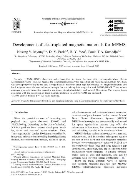
ARTICLE IN PRESS<br />
Journal <strong>of</strong> Magnetism and Magnetic Materials 265 (2003) 189–198<br />
<strong>Development</strong> <strong>of</strong> <strong>electroplated</strong> <strong>magnetic</strong> <strong>materials</strong> <strong>for</strong> <strong>MEMS</strong><br />
Nosang V. Myung a, *, D.-Y. Park b,1 , B.-Y. Yoo b , Paulo T.A. Sumodjo b,2<br />
a Jet Propulsion Laboratory, <strong>MEMS</strong> Technology Group, Cali<strong>for</strong>nia Institute <strong>of</strong> Technology, Mail-stop 302-306, 4800 Oak Grove,<br />
Pasadena, CA 91109, USA<br />
b Department <strong>of</strong> Chemical Engineering, University <strong>of</strong> Cali<strong>for</strong>nia, Los Angeles CA 90095, USA<br />
Received 18 February 2003; received in revised <strong>for</strong>m 11 March 2003<br />
Abstract<br />
Permalloy (19%Ni–81%Fe alloy) and nickel have thus far found the most utility in <strong>magnetic</strong>-Micro Electro<br />
Mechanical Systems (<strong>MEMS</strong>), because the technologies necessary <strong>for</strong> depositing and micromachining them have been<br />
well-developed previously by the data storage industry. However, other high per<strong>for</strong>mance s<strong>of</strong>t <strong>magnetic</strong> <strong>materials</strong> and<br />
hard <strong>magnetic</strong> <strong>materials</strong> have unique advantages that are driving their integration with <strong>MEMS</strong>/NEMS. These include<br />
enhanced <strong>magnetic</strong> properties, corrosion resistance, electrical resistivity, and reduced films stress. The primary issues<br />
associated with the integration <strong>of</strong> these <strong>magnetic</strong> <strong>materials</strong> in <strong>MEMS</strong>/NEMS are discussed.<br />
r 2003 Elsevier Science B.V. All rights reserved.<br />
Keywords: Magnetic films; Electrodeposition; S<strong>of</strong>t <strong>magnetic</strong> <strong>materials</strong>; Hard <strong>magnetic</strong> <strong>materials</strong>; Co-based alloys; <strong>MEMS</strong>/NEMS<br />
1. Introduction<br />
Given the prohibitive cost <strong>of</strong> launching any<br />
payload into space (between $10,000 and<br />
$1,000,000/kg, depending on the type <strong>of</strong> mission),<br />
NASA’s goal has been towards developing ‘‘smaller,<br />
faster and cheaper’’ space missions. Thus,<br />
‘‘microspacecraft’’ (under 100 kg mass) enabled by<br />
integrated microdevices including inertial guidance<br />
devices, micropropulsion devices, adaptive optics,<br />
*Corresponding author. Tel.: +1-818-3933239; fax: +1-818-<br />
3934540.<br />
E-mail address: nosang.v.myung@jpl.nasa.gov<br />
(N.V. Myung).<br />
1 Present address: Department <strong>of</strong> Applied Materials Engineering,<br />
Hanbat National University, San 16-1, Dukmyungdong,<br />
Yuseong-gu, Duejon, 305-719, South Korea.<br />
2 Visiting Scholar from Instituto de Qu!ımica, Universidade de<br />
S*ao Paulo, 05508-900 S*ao Paulo, SP, Brasil.<br />
microinstruments and nano-mechanical resonator<br />
devices are <strong>of</strong> great interest. In this context, Micro/<br />
Nano Electro Mechanical Systems (<strong>MEMS</strong>/<br />
NEMS) technologies are exceptionally well suited<br />
<strong>for</strong> space applications because they <strong>of</strong>fer the<br />
advantages <strong>of</strong> low mass, low power consumption<br />
and reliability, coupled with novel capabilities.<br />
<strong>MEMS</strong> devices such as microactuators, sensors,<br />
micromotors, and frictionless microgears require<br />
the use <strong>of</strong> both hard and s<strong>of</strong>t <strong>magnetic</strong> <strong>materials</strong><br />
because electro<strong>magnetic</strong>ally actuated <strong>MEMS</strong> are<br />
more stable <strong>for</strong> high <strong>for</strong>ce and large actuation gap<br />
applications. Moreover, they are less susceptible to<br />
malfunction when subjected to adverse environments<br />
such as dust and humidity, and can be<br />
actuated with low-cost voltage controllers [1–6].<br />
There are many different ways to deposit<br />
and integrate <strong>magnetic</strong> <strong>materials</strong> into <strong>MEMS</strong>/<br />
NEMS. Electrochemical processes including<br />
0304-8853/03/$ - see front matter r 2003 Elsevier Science B.V. All rights reserved.<br />
doi:10.1016/S0304-8853(03)00264-6
ARTICLE IN PRESS<br />
190<br />
N.V. Myung et al. / Journal <strong>of</strong> Magnetism and Magnetic Materials 265 (2003) 189–198<br />
electrodeposition and electroless deposition are<br />
well-suited to fulfill the requirements <strong>of</strong> high yield<br />
and cost effective processes. Electrochemical processes<br />
have many advantages, including precisely<br />
controlled near room temperature operation, lowenergy<br />
requirements, rapid deposition rates, capability<br />
to handle complex geometries, low cost,<br />
and simple scale-up with easily maintained equipment.<br />
In addition, the properties <strong>of</strong> <strong>materials</strong> can<br />
be ‘‘tailored’’ by controlling solution compositions<br />
and deposition parameters. Due to these advantages,<br />
<strong>electroplated</strong> s<strong>of</strong>t <strong>magnetic</strong> <strong>materials</strong> such as<br />
NiFe and CoNiFe have been widely used as<br />
recording head <strong>materials</strong> <strong>for</strong> computer hard drive<br />
industries [7]. In the case <strong>of</strong> <strong>magnetic</strong>-<strong>MEMS</strong>/<br />
NEMS, the <strong>magnetic</strong> layer thickness can vary<br />
from a few nanometers to a few mm depending on<br />
the applications. Magnetic thin films must also<br />
have good adhesion, low-stress, corrosion resistance,<br />
and be thermally stable with excellent<br />
<strong>magnetic</strong> properties.<br />
From the studies done at UCLA on electrodeposited<br />
CoNi and CoFe-based <strong>magnetic</strong> thin<br />
films, this paper reviews the dependence <strong>of</strong> the<br />
electrodeposited film properties on the various<br />
electroplating parameters including pH, temperature,<br />
metal ion concentration in the plating<br />
solution, complexing agents, other additives,<br />
current density (CD), and hydrodynamics. Some<br />
new results are also discussed. In addition, this<br />
paper reviews the currently available <strong>magnetic</strong><br />
<strong>materials</strong> <strong>for</strong> <strong>MEMS</strong>/NEMS applications that can<br />
be produced by electrodeposition, and the challenges<br />
associated with the development <strong>of</strong> these<br />
<strong>materials</strong>.<br />
2. Results and discussion<br />
2.1. S<strong>of</strong>t <strong>magnetic</strong> <strong>materials</strong> in <strong>MEMS</strong><br />
The most commonly used <strong>magnetic</strong> <strong>materials</strong> in<br />
<strong>MEMS</strong> are s<strong>of</strong>t <strong>magnetic</strong> <strong>materials</strong>, such as<br />
permalloy (19%Ni–81%Fe alloy). The combination<br />
<strong>of</strong> relatively high <strong>magnetic</strong> saturation<br />
(B S E1 T), low coercivity (low-hysteresis loss),<br />
good corrosion resistance, and near zero magnetostriction<br />
(i.e. <strong>magnetic</strong> properties not affected by<br />
film stress) has led to the use <strong>of</strong> electrodeposited<br />
permalloy films in macroscopic and microscopic<br />
sensors, actuators, and systems. Perhaps the most<br />
significant application <strong>of</strong> permalloy in <strong>MEMS</strong> is in<br />
<strong>magnetic</strong> recording heads. The technologies necessary<br />
<strong>for</strong> the deposition and micromachining <strong>of</strong><br />
permalloy are fairly well developed.<br />
As the data storage density <strong>of</strong> computer drives<br />
increases dramatically (60% per year), new, highper<strong>for</strong>mance,<br />
s<strong>of</strong>t <strong>magnetic</strong> <strong>materials</strong> are being<br />
considered and studied <strong>for</strong> possible use. Andriacos<br />
and Robertson reviewed the requirements <strong>for</strong><br />
improved thin film recording heads [7]. These<br />
include: (1) high <strong>magnetic</strong> saturation (B S b1T;<br />
currently thin film B S is in the range <strong>of</strong> 2.3–2.4 T),<br />
(2) low coercivity (H c o1 Oe), (3) optimal anisotropy<br />
field (H k ) <strong>for</strong> high permeability (m), (4) near<br />
zero magnetostriction (l), (5) high-electrical resistivity<br />
(r) and (6) good corrosion resistance.<br />
Various CoFe- and CoNi-based ternary and<br />
quaternary alloys have been considered <strong>for</strong> meeting<br />
the challenges <strong>of</strong> improved corrosion resistance,<br />
and lower film stress with superior s<strong>of</strong>t<br />
<strong>magnetic</strong> properties. These electrodeposited alloys<br />
include CoFeB, CoFeCr, CoFeP, CoFeCu,<br />
CoNiFe, CoNiFeS, CoFeNiCr, CoFeSnP and<br />
CoNiFeB [7].<br />
2.1.1. Magnetic properties <strong>of</strong> s<strong>of</strong>t <strong>magnetic</strong><br />
<strong>materials</strong><br />
Magnetic saturation <strong>of</strong> electrodeposited ferro<strong>magnetic</strong><br />
<strong>materials</strong> is only dependent on the<br />
composition. This is to be expected because B S is<br />
a structure insensitive property [8]. There<strong>for</strong>e,<br />
<strong>magnetic</strong> saturation <strong>of</strong> electrodeposited <strong>materials</strong><br />
will only change with electroplating conditions<br />
when changes in the conditions lead to deposit<br />
composition changes. The highest <strong>magnetic</strong> saturation<br />
(up to 2.4 T) ever obtained experimentally<br />
was <strong>for</strong> CoFe alloys with Fe compositions in<br />
the range from 55% to 78%. Liao reported<br />
that electrodeposited CoFe alloys, especially<br />
90Co10Fe, have promising <strong>magnetic</strong> properties,<br />
including high <strong>magnetic</strong> saturation (1.9 T), low<br />
coercivity (1 Oe) and near zero magnetostriction<br />
[9]. However, those alloys exhibited very poor<br />
corrosion resistance and high film stress. CoNiFe<br />
alloys have attracted attention in the data storage
ARTICLE IN PRESS<br />
N.V. Myung et al. / Journal <strong>of</strong> Magnetism and Magnetic Materials 265 (2003) 189–198 191<br />
industry due to their high <strong>magnetic</strong> saturation<br />
(upto 2.4 T) [10]. In addition, it has been shown<br />
that ternary 80Co10Ni10Fe electrodeposited films<br />
exhibit zero magnetostriction with B S values<br />
around 1.6 T [11].<br />
Fig. 1 shows the <strong>magnetic</strong> saturation <strong>of</strong> NiFe,<br />
NiCo, CoFe, and CoNiFe films electrodeposited<br />
from chloride and sulfate baths [12,13]. It is seen<br />
that <strong>for</strong> the Ni-based alloys, the <strong>magnetic</strong> saturation<br />
decreased linearly with increasing Ni content<br />
(Fig. 1a). This is explained in terms <strong>of</strong> composition<br />
Fig. 1. Magnetic Saturation <strong>of</strong> electrodeposited: (a) NiFe,<br />
NiCo, and (b) CoFe, and CoNiFe films (Refs. [11,12]).<br />
changes. As it is seen in Fig. 1b, nature <strong>of</strong> anion in<br />
the plating bath does not affect the <strong>magnetic</strong><br />
saturation <strong>of</strong> the electrodeposited film. Addition <strong>of</strong><br />
Fe (up to 50%) to both pure Co and CoNi thin<br />
films increased the B S values sigmoidally from<br />
B1.5 T (no Fe added) to a maximum <strong>of</strong> B2.0 T.<br />
The addition <strong>of</strong> Ni in CoFe alloys, however, has<br />
negligible effect on the <strong>magnetic</strong> saturation values.<br />
Varying impurity concentrations have shown to<br />
result in slightly different <strong>magnetic</strong> saturation<br />
values <strong>for</strong> films with similar compositions. For<br />
example, higher B S values <strong>of</strong> CoNiFe films were<br />
obtained using additive free electrolytes rather<br />
than electrolytes containing additives (e.g. saccharin)<br />
[14]. As emphasized, <strong>magnetic</strong> properties are<br />
extrinsic properties, and are thus influenced only<br />
by film composition. However, film stress, grain<br />
size, crystal structure, surface roughness, and film<br />
thickness are factors that can affect the <strong>magnetic</strong><br />
properties <strong>of</strong> the deposited film. Osaka et al.<br />
observed that the coercivity <strong>of</strong> electrodeposited<br />
CoNiFe films from an electrolyte solution containing<br />
saccharin or thiourea as additives (stress<br />
reducers or grain refiners) is closely related to the<br />
sulfur content <strong>of</strong> the film [14].<br />
2.1.2. Corrosion resistance <strong>of</strong> s<strong>of</strong>t <strong>magnetic</strong><br />
<strong>materials</strong><br />
Corrosion resistance or chemical stability <strong>of</strong><br />
the electrodeposited film is not only dependent on<br />
film composition, but is also a property <strong>of</strong> its<br />
crystal structure, grain size and impurity content.<br />
In general, among the iron group metals, nickel<br />
has the greatest corrosion resistance in acidic<br />
media, followed by cobalt. Iron is the most<br />
susceptible to corrosion. The corrosion resistance<br />
<strong>of</strong> iron group alloys decreases significantly with<br />
increasing Fe content. Ulhig explained this behavior<br />
via his electron configuration theory <strong>of</strong><br />
passivity [15]. Accordingly, the corrosion rate<br />
decreases substantially with increasing Ni content<br />
up to a critical composition <strong>of</strong> 34% Ni. For Ni<br />
contents greater than 34%, the corrosion behavior<br />
<strong>of</strong> the alloy is approximately that <strong>of</strong> the pure<br />
nickel phase.<br />
In NiFe alloys, the corrosion resistance <strong>of</strong> the<br />
Ni-rich FCC phase is higher than that <strong>for</strong> the Ferich<br />
BCC phases in chloride media. 50Ni50Fe
ARTICLE IN PRESS<br />
192<br />
N.V. Myung et al. / Journal <strong>of</strong> Magnetism and Magnetic Materials 265 (2003) 189–198<br />
Fig. 2. Comparison <strong>of</strong> corrosion (polarization) resistances (R p )<br />
<strong>of</strong> iron group alloys in 0.5 M NaCl after 1 h immersion<br />
(Ref. [12]). Corrosion resistance is inversely proportional to<br />
the corrosion rate.<br />
deposits exhibited the greatest corrosion resistance,<br />
probably due to the smaller grain<br />
sizes. Similarly, the Co-rich HCP phase <strong>of</strong> CoNi<br />
alloys has lower corrosion resistance than the<br />
Ni-rich FCC phase. Nanocrystalline FCC<br />
70Ni30Co deposits exhibited the highest corrosion<br />
resistance among the CoNi alloys. The corrosion<br />
resistance <strong>of</strong> CoFe alloys are much lower than<br />
that <strong>for</strong> FCC NiFe and FCC CoNi alloys<br />
in chloride media. Substantial improvements<br />
in corrosion resistance are obtained by the<br />
addition <strong>of</strong> Ni to electrodeposited CoFe alloys.<br />
Conversely, the addition <strong>of</strong> B has only a slight<br />
effect on the corrosion resistance. We have<br />
determined the corrosion resistance <strong>of</strong> various<br />
alloys and Fig. 2 compares the obtained values <strong>for</strong><br />
iron group alloys after 1 h <strong>of</strong> immersion in 0.5 M<br />
NaCl [12].<br />
Electrodeposited films are more susceptible to<br />
corrosion than physical vapor deposited films or<br />
bulk alloys because the presence <strong>of</strong> organic<br />
additives (e.g. saccharin or thiourea) in the<br />
electrodeposition bath leads to the deposition <strong>of</strong><br />
a film that is anodically active, preventing the<br />
<strong>for</strong>mation <strong>of</strong> a passive film [16].<br />
2.1.3. Electrical resistivity <strong>of</strong> s<strong>of</strong>t <strong>magnetic</strong><br />
<strong>materials</strong><br />
A consequence <strong>of</strong> the drive <strong>for</strong> increasing data<br />
rates in data storage industry and <strong>for</strong> applications<br />
in RF <strong>MEMS</strong> is the requirement <strong>for</strong> faster<br />
switching <strong>of</strong> <strong>magnetic</strong> <strong>materials</strong>. Rapid <strong>magnetic</strong><br />
field switching results in the <strong>for</strong>mation <strong>of</strong> eddy<br />
currents, which can dramatically reduce the<br />
effective permeability <strong>of</strong> <strong>magnetic</strong> films during<br />
high frequency operation [7]. Two different<br />
approaches, the use <strong>of</strong> multilayered structures<br />
and increasing film resistance via impurity incorporation,<br />
were proposed to minimize eddy currents<br />
[7,11]. Yokoshima et al. [11] observed an<br />
increase in electrical resistivity from approximately<br />
20–130 mO cm with the addition <strong>of</strong> diethylenetriamine<br />
(DET) (up to 20 g/l) into the plating solution.<br />
This effect was attributed to carbon incorporation<br />
in the films, resulting in increased impurity-based<br />
electron scattering and a change in microstructure.<br />
However, increases in electrical resistivity via<br />
impurity incorporation can be detrimental by also<br />
decreasing the <strong>magnetic</strong> saturation <strong>of</strong> the material.<br />
Fig. 3 shows the electrical resistivity <strong>of</strong> electrodeposited<br />
NiFe and CoNi thin films and<br />
<strong>for</strong> comparison, the electrical resistivity <strong>of</strong> bulk<br />
CoNi alloys. It is seen that the electrical resistivity<br />
<strong>of</strong> electrodeposited NiFe alloys decreases<br />
Fig. 3. Electrical resistivity <strong>of</strong> NiFe and CoNi thin films<br />
electrodeposited from chloride baths and bulk CoNi (Ref. [12]).
ARTICLE IN PRESS<br />
N.V. Myung et al. / Journal <strong>of</strong> Magnetism and Magnetic Materials 265 (2003) 189–198 193<br />
monotonically with increasing Ni content from<br />
40% to 100% Ni. The electrical resistivity <strong>of</strong> NiFe<br />
films (thickness X1 mm) with high Fe content<br />
(>40%) is difficult to measure due to the<br />
<strong>for</strong>mation <strong>of</strong> stressed, and cracked deposits. In<br />
contrast, the electrical resistivity <strong>of</strong> both electrodeposited<br />
and bulk CoNi alloys remains practically<br />
constant, around 10 mO cm, <strong>for</strong> Ni contents<br />
below 40%. For bulk CoNi alloys with higher Ni<br />
contents, the resistivity increases slightly with<br />
increasing Ni content, exhibiting a maximum at<br />
about 70% Ni. Electrodeposited CoNi alloys also<br />
show the same trend (with a maximum around<br />
80% Ni). However, the resistivity <strong>of</strong> electrodeposited<br />
alloys is considerably higher in comparison to<br />
bulk alloys. This higher electrical resistivity <strong>of</strong><br />
the electrodeposited CoNi alloys can be attributed<br />
to the smaller grain sizes, high defect<br />
densities, and impurity incorporation during electrodeposition<br />
[12].<br />
2.1.4. Residual stress <strong>of</strong> s<strong>of</strong>t <strong>magnetic</strong> <strong>materials</strong><br />
Residual stress in the electrodeposited films is an<br />
important factor <strong>for</strong> <strong>MEMS</strong> devices because,<br />
unlike in the data storage application, the thickness<br />
<strong>of</strong> <strong>magnetic</strong> films in <strong>MEMS</strong> can range from<br />
nanometers (e.g. NEMS devices) to few millimeters<br />
thick (e.g. LIGA devices). In many cases,<br />
this film stress could exceed the strength <strong>of</strong> the<br />
film, resulting in cracking, de<strong>for</strong>mation <strong>of</strong> devices,<br />
and interfacial failure.<br />
Two kinds <strong>of</strong> film stress exist in electrodeposited<br />
<strong>materials</strong>: differential thermal stress and residual<br />
stress. Thermal stress occurs as a consequence <strong>of</strong><br />
high temperature electrodeposition or <strong>of</strong> heating<br />
<strong>of</strong> the bath during electrodeposition. The magnitude<br />
<strong>of</strong> the stress can be calculated by knowing the<br />
thermal expansion coefficients <strong>of</strong> the electrodeposited<br />
material and the substrate, respectively, and<br />
can be minimized by optimizing the electrodeposition<br />
conditions at temperatures closer to room<br />
temperature. Residual stress, on the other hand, is<br />
defined as the stress within the electrodeposited<br />
material, which does not arise from mechanical<br />
loading or temperature gradients, but yet remains<br />
in internal equilibrium [17]. Many factors contribute<br />
to the development <strong>of</strong> residual stress in<br />
deposits, including film composition, nature <strong>of</strong> the<br />
substrate surface and <strong>of</strong> the deposit, solution<br />
composition (metal ion concentration, pH, complexing<br />
agent, additives, and anions), temperature,<br />
current density, current wave<strong>for</strong>m, agitation, and<br />
the deposit thickness. Dini [17] observed that in<br />
electrodeposited transition metals, which exhibit<br />
the highest residual stress values, there is an<br />
apparent relationship between the stress and the<br />
melting points <strong>of</strong> these metals. Generally, a high<br />
residual stress is observed at the beginning <strong>of</strong> the<br />
electrodeposition, reaching a constant value <strong>for</strong><br />
thicknesses in the range <strong>of</strong> 12.5–25 mm. The high<br />
initial intrinsic stress in the deposit is associated<br />
with lattice mismatch and with the grain size <strong>of</strong> the<br />
underlying substrate.<br />
Since there are many parameters affecting the<br />
stress <strong>of</strong> deposits, deposition conditions must be<br />
optimized on an individual basis. Fig. 4 shows the<br />
effect <strong>of</strong> current density on the residual stress<br />
and surface morphology <strong>of</strong> nickel, 40Co60Ni,<br />
85Co15Ni electrodeposits. Lower current densities<br />
lead to the <strong>for</strong>mation <strong>of</strong> stressed deposits. With<br />
increasing current density, stress tends to decrease.<br />
From Fig. 4b it can be seen that the morphology<br />
<strong>of</strong> the film is also highly dependent on the applied<br />
current density.<br />
Best-known stress reducing agents <strong>for</strong> nickel<br />
electrodeposition are sulfur containing organic<br />
additives (e.g. saccharin, thiourea, aminobenzene<br />
sulfonic acid, benzene sulfamide, benzene sulfonic<br />
acid, etc.) [17]. Thiourea also influences the<br />
residual stress in cobalt electrodeposits. Slightly<br />
compressive cobalt films were obtained using a<br />
plating solution containing 25–50 mg/l thiourea<br />
[18]. These sulfur containing organic additives<br />
suffer decomposition on the substrate surface and<br />
the products are partially incorporated in the<br />
deposit (e.g. sulfur, carbon, or both). Fig. 5 shows<br />
the effect <strong>of</strong> saccharin concentration on the<br />
residual stress <strong>of</strong> Ni, 85Co15Ni, and 65Co15Ni-<br />
20Fe films (residual stress data <strong>for</strong> the 65Co15Ni-<br />
20Fe film is taken from literature [19]). The anion<br />
<strong>of</strong> the plating solution can also change stress <strong>of</strong> the<br />
material. We have seen that <strong>for</strong> deposition <strong>of</strong> the<br />
85Co15Ni alloy, residual stress is slightly lower in<br />
the film deposited from a chloride bath compared<br />
to the material deposited from a sulfamate bath, in<br />
the presence <strong>of</strong> saccharin. Small additions <strong>of</strong>
ARTICLE IN PRESS<br />
194<br />
N.V. Myung et al. / Journal <strong>of</strong> Magnetism and Magnetic Materials 265 (2003) 189–198<br />
Fig. 5. Residual stress <strong>of</strong> electrodeposited Ni, 85Co15Ni, and<br />
65Co15Ni20Fe films. Ni and 85Co15Ni were electrodeposited<br />
from sulfamate baths; 65Co15Ni20Fe film data is from<br />
literature [19].<br />
Fig. 4. Effect <strong>of</strong> current density on: (a) intrinsic stress <strong>of</strong> nickel,<br />
40Co60Ni, and 85Co15Ni films, and (b) microstructure <strong>of</strong> Ni<br />
films electrodeposited at different current densities. Nickel<br />
plating solution is 1 M Ni sulfamate bath, pH = 4.0, Temp =<br />
60 C; 40Co60Ni plating solution is 0.2 M NiCl 2 +0.05 M<br />
CoCl 2 +0.7 M NaCl+0.4 M boric acid+0.009 M NaH 2 PO 2<br />
+75 mM saccharin, 85Co15Ni plating solution is 0.2 M<br />
NiCl 2 +0.206 M CoCl 2 +0.7 M NaCl+0.4 M boric acid<br />
+0.009 M NaH 2 PO 2 +75 mM saccharin.<br />
saccharin to plating solutions can alter the residual<br />
stress <strong>of</strong> nickel from tensile to compressive.<br />
2.2. Hard <strong>magnetic</strong> <strong>materials</strong> in <strong>MEMS</strong><br />
Although s<strong>of</strong>t <strong>magnetic</strong> <strong>materials</strong> can be used<br />
to produce high-<strong>for</strong>ce actuators and sensitive<br />
magnetometers, hard <strong>magnetic</strong> or permanent<br />
<strong>magnetic</strong> <strong>materials</strong> would be more appropriate in<br />
some cases. For example, hard <strong>magnetic</strong> <strong>materials</strong><br />
with a high remanence, B r ; are well suited <strong>for</strong> bidirectional<br />
(push-pull) microactuator applications<br />
[20]. In addition, microactuators driven by <strong>of</strong>fchip<br />
coils can be activated with lower fields and<br />
hence lower power levels if a hard <strong>magnetic</strong><br />
material is used instead <strong>of</strong> a s<strong>of</strong>t <strong>magnetic</strong><br />
material. However, except in a few cases, hard<br />
<strong>magnetic</strong> <strong>materials</strong> have not been used extensively<br />
in <strong>MEMS</strong> [6]. The primary reason <strong>for</strong> this is the<br />
lack <strong>of</strong> readily available and reliable deposition<br />
and micromachining processes. A large variety <strong>of</strong><br />
hard <strong>magnetic</strong> <strong>materials</strong> can be prepared by<br />
metallurgical processes (e.g. sintering, pressure<br />
bonding, injection molding, casting, extruding,<br />
and calendaring), vacuum processes (e.g. evaporation,<br />
sputtering, MBE, CVD) and electrochemical<br />
processes (e.g. electroless deposition and electrodeposition).<br />
2.2.1. Magnetic properties <strong>of</strong> hard <strong>magnetic</strong><br />
<strong>materials</strong><br />
To date, most hard <strong>magnetic</strong> <strong>materials</strong> have<br />
been alloys based on cobalt because its HCP
ARTICLE IN PRESS<br />
N.V. Myung et al. / Journal <strong>of</strong> Magnetism and Magnetic Materials 265 (2003) 189–198 195<br />
crystalline structure is highly anisotropic. Electrochemically,<br />
Co-based alloys containing P, As, Sb,<br />
Bi, W, Cr, Mo, Pd, Pt, Ni, Fe, Cu, Mn, O and H<br />
have been deposited. Alloying elements tend to<br />
concentrate at the grain boundaries. Thus, the<br />
resulting structure consists <strong>of</strong> isolated <strong>magnetic</strong> Co<br />
grains surrounded by non-<strong>magnetic</strong> or weakly<br />
<strong>magnetic</strong> boundaries [21]. Such microstructural<br />
<strong>for</strong>mations increase the energy barrier <strong>for</strong> <strong>magnetic</strong><br />
realignment <strong>of</strong> the domains and thereby<br />
increase the overall coercivity H C <strong>of</strong> the films,<br />
making them <strong>magnetic</strong>ally hard. We have observed<br />
that the addition <strong>of</strong> phosphorus into<br />
electrodeposited CoNi films produced nanocrystalline<br />
films with a modified crystal structure,<br />
increasing the energy barriers required <strong>for</strong> the<br />
<strong>magnetic</strong> alignment <strong>of</strong> the CoNi grains [22].<br />
Elements that are exceptions to this rule are Pd<br />
and Pt, which are readily alloyed with Co or CoNi<br />
and instead have the effect <strong>of</strong> increasing the<br />
magnetocrystalline anisotropy [23]. Luborsky’s<br />
experiments with electrodeposited Co and CoNi<br />
containing P, As, Sb, Bi, W, Mo and Cr as alloying<br />
elements showed that the concentration <strong>of</strong> the<br />
alloying element required <strong>for</strong> maximum coercivity<br />
decreased in the following orders P>As>Sb>Bi<br />
and W>Mo>Cr [21]. Also, as expected, the<br />
<strong>magnetic</strong> saturation B S ; decreases with increasing<br />
content <strong>of</strong> the non-<strong>magnetic</strong> alloying element.<br />
Low alloy concentrations <strong>of</strong> phosphorus and<br />
tungsten, however, have resulted in films with<br />
high coercivity with yet having relatively high B S :<br />
Promising hard <strong>magnetic</strong> thin film <strong>materials</strong><br />
include CoPt and FePt due to their high magnetocrystalline<br />
anisotropy and <strong>magnetic</strong> saturation<br />
[23]. Specifically, L 1O ordered phase <strong>materials</strong><br />
(Co50Pt50 and Fe50Pt50) show extremely high<br />
coercivities (>10,000 Oe) [24]. Most investigations<br />
<strong>of</strong> CoPt and FePt <strong>magnetic</strong> thin films were<br />
conducted using vacuum-based processes (e.g.<br />
MBE [25] and sputtering [24–27]), in which CoPt<br />
and FePt were deposited as multilayered structures<br />
and then annealed to produce ordered phases. A<br />
major disadvantage <strong>of</strong> these deposition methods<br />
<strong>for</strong> some <strong>magnetic</strong> <strong>MEMS</strong> applications is the<br />
requirement <strong>for</strong> high-temperature post-annealing<br />
processes (e.g. 500–700 C). Integrated circuits and<br />
some <strong>materials</strong> commonly used in <strong>MEMS</strong> (e.g. Al,<br />
polymer, etc.) do not survive at these temperatures.<br />
Although Farrow and Marks report that by<br />
electrochemically charging the transition metal<br />
alloy films with hydrogen, one can minimize the<br />
effects <strong>of</strong> the annealing process [27], it is nevertheless<br />
still a problem. CoPt and Co/Pt multilayers<br />
can be electrodeposited from various plating<br />
solutions at or near room temperature [28–32].<br />
Cavallotti et al. obtained hard <strong>magnetic</strong> Co–Pt<br />
electrodeposits with a coercivity that ranged from<br />
4000 to 2000 Oe <strong>for</strong> film thicknesses from 50 nm to<br />
10 mm [32].<br />
In our laboratories we also studied various<br />
electrodeposited hard <strong>magnetic</strong> Co-based alloys<br />
and found promising hard <strong>magnetic</strong> properties.<br />
Coercivity in the direction parallel to the film<br />
decreased in the following sequence: CoPtP>Co-<br />
NiPECoP>CoMnP>CoW. In the perpendicular<br />
direction, coercivity decreased in the sequence <strong>of</strong><br />
CoPtP>CoNiPECoMnP>CoP>Co/Cu multilayers>CoW<br />
[33]. Fig. 6 shows the dependence<br />
<strong>of</strong> deposit P content <strong>of</strong> CoNiP alloys with P source<br />
concentration, Na 2 H 2 PO 2 , in the plating bath. It<br />
shows that <strong>for</strong> [NaH 2 PO 2 ] o5 g/l, small increase in<br />
concentration caused a high increase in P content<br />
in the deposit. With increasing [NaH 2 PO 2 ] the rate<br />
<strong>of</strong> increase <strong>of</strong> deposited P content decreased. It is<br />
Fig. 6. Effect <strong>of</strong> P source concentration in the plating bath<br />
[NaH 2 PO 2 ], on the deposit P content <strong>of</strong> CoNiP thin films.
ARTICLE IN PRESS<br />
196<br />
N.V. Myung et al. / Journal <strong>of</strong> Magnetism and Magnetic Materials 265 (2003) 189–198<br />
Fig. 7. Dependence <strong>of</strong> <strong>magnetic</strong> saturation with deposit P<br />
content <strong>for</strong> two different CoNiP electrodeposited thin films.<br />
Fig. 9. Hysteresis loop (a) and 2nd quadrant (b) B2H curves<br />
<strong>for</strong> various electrodeposited <strong>magnetic</strong> alloys.<br />
Fig. 8. Coercivity <strong>of</strong> electrodeposited NiP 40Co60NiP,<br />
85Co15NiP and CoP films: All films were electrodeposited<br />
from chloride baths.<br />
also seen that the alloy that is richer in Co can<br />
incorporate more phosphorus.<br />
Fig. 7 shows how the <strong>magnetic</strong> saturation <strong>of</strong><br />
CoNiP alloys varies with deposit P content. It<br />
shows that B S varies linearly with P content and<br />
that Co-based alloys have higher <strong>magnetic</strong> saturation,<br />
as cobalt has a higher B S value. The variation<br />
<strong>of</strong> coercivity <strong>of</strong> different phosphorus containing<br />
alloys with the P content is shown in Fig. 8. Non-<br />
Ni containing alloys, such as CoP, exhibit<br />
increasing coercivity with increasing P incorporation<br />
into the alloy. On the other hand, Ni<br />
containing alloys show this increase in coercivity<br />
with increasing amount <strong>of</strong> P in the alloy, only <strong>for</strong><br />
low P concentrations. As more phosphorus is<br />
added to these alloys, the coercivity reaches a<br />
maximum, followed by a significant reduction at<br />
high P concentrations. The highest coercivities<br />
were observed <strong>for</strong> the (85Co15Ni) 100 X P X films.<br />
Fig. 9 shows the hysteresis loops (Fig. 9a) and 2nd
ARTICLE IN PRESS<br />
N.V. Myung et al. / Journal <strong>of</strong> Magnetism and Magnetic Materials 265 (2003) 189–198 197<br />
Table 1<br />
Stress and <strong>magnetic</strong> properties <strong>of</strong> electrodeposited Ni, (Co 85 Ni 15 ) 100 X P X , and Ni/(Co 85 Ni 15 ) 100 X P X /Ni composite films<br />
Electrodeposited film Thickness (mm) Stress (MPa) H c;parallel (Oe) B S =T S parallel<br />
Ni a 5 100 21 0.6 0.02<br />
(Co 85 Ni 15 ) 100<br />
b<br />
X P X 5 200 324 1.3 0.40<br />
Ni/(Co 85 Ni 15 ) 100 X P X /Ni 0.8/3.3/0.8 total <strong>of</strong> 5 66 294 1.1 0.42<br />
a Ni bath composition: 1 M nickel sulfamate+0.5 M boric acid+10 mM saccharin; pH=4, current density=10 mA cm 2 .<br />
b CoNiP bath composition: 0.2 M NiCl 2 +0.206 M CoCl 2 +0.7 M NaCl+0.4 M boric acid+0.009 M NaH 2 PO 2 +75 mM saccharin,<br />
pH=4, current density=10 mA cm 2 .<br />
quadrant B2H curves (Fig. 9b) <strong>for</strong> these various<br />
electrodeposited alloys.<br />
2.2.2. Corrosion resistance <strong>of</strong> hard <strong>magnetic</strong><br />
<strong>materials</strong><br />
As shown in Fig. 2, electrodeposited cobalt is<br />
much more susceptible to corrosion attack than<br />
either nickel or permalloy. Non-<strong>magnetic</strong> alloying<br />
elements (e.g. phosphorus, tungsten, manganese)<br />
are not beneficial in this respect and can significantly<br />
lower the corrosion resistance <strong>of</strong> these<br />
alloys. Furthermore, it has been observed that<br />
some <strong>of</strong> these hard <strong>magnetic</strong> <strong>materials</strong> are etched<br />
away during the photoresist removal step during<br />
lithographic patterning. It is there<strong>for</strong>e recommended<br />
that these <strong>magnetic</strong> <strong>materials</strong> have an<br />
overcoat <strong>of</strong> high corrosion resistance <strong>materials</strong><br />
(e.g. Au, Pt, Ni) in order to prevent their<br />
dissolution during <strong>MEMS</strong> processing.<br />
2.2.3. Residual stress <strong>of</strong> hard <strong>magnetic</strong> <strong>materials</strong><br />
In general, hard <strong>magnetic</strong> alloys become mechanically<br />
brittle and hard as their <strong>magnetic</strong><br />
hardness increases. There<strong>for</strong>e, this reduction in<br />
mechanical ductility results also in hard <strong>magnetic</strong><br />
<strong>materials</strong> having high residual stress. Fig. 8 shows<br />
the residual stress <strong>of</strong> electrodeposited CoNiP and<br />
CoP films plotted as a function <strong>of</strong> the P content.<br />
Electrodeposited CoNiP and CoP films have a<br />
much higher (above 200 MPa) tensile residual<br />
stress than pure nickel or cobalt films and show<br />
a maximum in the residual stress when the<br />
electrolyte baths concentrations <strong>of</strong> NaH 2 PO 2 are<br />
in the range <strong>of</strong> 1–2 g/l. In order to lower the<br />
residual stress while yet maintaining high coercivity,<br />
composite films consisting <strong>of</strong> these highly<br />
tensile <strong>magnetic</strong> films sandwiched between compressive<br />
films can be electrodeposited. Table 1<br />
shows plating conditions and film characteristics<br />
<strong>of</strong> a multilayered composite consisting <strong>of</strong> electrodeposited<br />
alternating layers <strong>of</strong> Ni and (85Co-<br />
15Ni) 100 X P X films. It shows that in fact, residual<br />
stress can be reduced by producing such composite<br />
<strong>materials</strong>, in the case, from a residual stress <strong>of</strong><br />
around 200 MPa <strong>for</strong> the alloy film down to<br />
66 MPa to a multilayered composite. Ni/CoNiP<br />
composite films can maintain their hard <strong>magnetic</strong><br />
properties while reducing the film stress.<br />
3. Conclusion<br />
Magnetic <strong>materials</strong>, particularly ferro<strong>magnetic</strong><br />
<strong>materials</strong>, have many uses in <strong>MEMS</strong>. Although<br />
s<strong>of</strong>t <strong>magnetic</strong> <strong>materials</strong> have found the greatest<br />
utility in <strong>MEMS</strong>, improved processes <strong>for</strong> integrating<br />
hard <strong>magnetic</strong> <strong>materials</strong> with <strong>MEMS</strong><br />
are being developed. These electrochemical<br />
processes and resulting properties <strong>of</strong> the deposited<br />
<strong>magnetic</strong> films must be further optimized <strong>for</strong><br />
use in high-<strong>for</strong>ce microactuators and low-power<br />
microsensors.<br />
Acknowledgements<br />
The authors wish to acknowledge thier collaborators,<br />
including T. George, D. Wiberg, K.-ah<br />
Son, B. Eyre, O. Orient, D. Miller from JPL and<br />
K. Nobe, M. Schwartz and J.W. Judy from<br />
UCLA. This work was supported by the NASA<br />
Code-R and DARPA <strong>MEMS</strong> Program DABT63-<br />
99-1-0020.
ARTICLE IN PRESS<br />
198<br />
N.V. Myung et al. / Journal <strong>of</strong> Magnetism and Magnetic Materials 265 (2003) 189–198<br />
References<br />
[1] J.W. Judy, R.S. Muller, H.H. Zappe, IEEE J. Microelectromech.<br />
Syst. 4 (1995) 162.<br />
[2] J.W. Judy, R.S. Muller, Sensors Actuators (Physical A) A<br />
53 (1996) 392.<br />
[3] J.W. Judy, R.S. Muller, IEEE J. Microelectromech. Syst. 6<br />
(1997) 249.<br />
[4] C.H. Ahn, M.G. Allen, IEEE Trans. Ind. Electron. 45<br />
(1998) 866.<br />
[5] T.M. Liakopoulos, M. Xu, C.H. Ahn, Technical Digest<br />
Solid-State Sensor and Actuator Workshop, Vol. 19,<br />
Hilton Head Island, SC, USA, 1998.<br />
[6] T.S. Chin, J. Magn. Magn. Mater. 209 (2000) 75.<br />
[7] P.C. Andricacos, N. Robertson, IBM J. Res. Develop. 42<br />
(1998) 671.<br />
[8] C. Chen, Magnetism and Metallurgy <strong>of</strong> S<strong>of</strong>t Magnetic<br />
Materials, Dover, New York, 1986, p. 98.<br />
[9] S.H. Liao, IEEE Trans. Magn. 23 (1998) 2981.<br />
[10] C. Bonhote, E.I. Cooper, L.T. Romankiw, H. Xu, 204th<br />
Meeting <strong>of</strong> the Electrochemical Society, Salt Lake City,<br />
2002. Abstract Book, Abstract # 508.<br />
[11] T. Yokoshima, M. Kaseda, M. Yamada, T. Nakanishi, T.<br />
Momma, T. Osaka, IEEE Trans. Magn. 35 (1999) 2499.<br />
[12] N.V. Myung, K. Nobe, J. Electrochem. Soc. 148 (2001)<br />
C133.<br />
[13] D. Kim, D.-Y. Park, B.Y. Yoo, P.T.A. Sumodjo, N.V.<br />
Myung, Electrochim. Acta 48 (2003) 819.<br />
[14] T. Osaka, T. Sawaguchi, F. Mizutani, T. Yokoshina, J.<br />
Electrochem. Soc. 146 (1999) 3295.<br />
[15] H.H. Uhlig, Corrosion Handbook, Wiley, New York,<br />
1948, pp. 194.<br />
[16] G.S. Frankel, V. Brusic, R.G. Schad, J.-W. Chang, Corr.<br />
Sci. 35 (1993) 63.<br />
[17] J.W. Dini, Electrodeposition—The Materials Science <strong>of</strong><br />
Coating and Substrates, Noyes Publications, 1993 (Chapter<br />
9).<br />
[18] Yu.K. Vyagis, A.I. Bodnevas, Yu. Matulis, Prot. Metals 1<br />
(1965) 468.<br />
[19] I. Tabakovic, V. Inturi, S. Riemer, J. Electrochem. Soc.<br />
149 (2002) C18.<br />
[20] H.J. Cho, S. Bhansali, C.H. Ahn, J. Appl. Phys. 87 (2000)<br />
6340.<br />
[21] F.E. Luborsky, IEEE Trans. Magn. 6 (1970) 502.<br />
[22] D.-Y. Park, N.V. Myung, M. Schwartz, K. Nobe,<br />
Electrochim. Acta 47 (2002) 2893.<br />
[23] R.M. Bozorth, Ferromagnetism, D. Van Nostrand, 1963<br />
(Chapter 5).<br />
[24] K.R. C<strong>of</strong>fey, M.A. Parker, J.K. Howard, IEEE Trans.<br />
Magn. 31 (1995) 2737.<br />
[25] C.H. Lee, R.F.C. Farrow, C.J. Lin, E.E. Marinero, Phys.<br />
Rev. B 42 (7) (1990) 11384.<br />
[26] P.F. Garcia, Z.G. Li, W.B. Zeper, J. Magn. Magn. Mater.<br />
121 (1993) 452.<br />
[27] R.F. Farrow, R.F. Marks, US Patent #5,792,510.<br />
[28] Y. Jyoko, S. Kashiwabara, Y. Hayashi, W. Schwarzacher,<br />
J. Magn. Magn. Mater. 198/99 (1999) 239.<br />
[29] J. Horkans, D.J. Seagle, C.H. Chang, J. Electrochem. Soc.<br />
137 (1990) 2056.<br />
[30] M. Monew, I. Krastev, A. Zielonka, J. Phys. Condens.<br />
Matter 49 (1999) 10033.<br />
[31] V. Tutovan, V. Georgescu, Thin Solid Films 61 (1970) 133.<br />
[32] P.L. Cavallotti, N. Lecis, H. Fauser, A. Zielonka, J.P.<br />
Celis, G. Wouters, J. Machado da Silva, J.M.B. Oliveira,<br />
M.A. Sa, Surf. Coat. Technol. 105 (1998) 232.<br />
[33] N.V. Myung, D.-Y. Park, M. Schwartz, K. Nobe, H.<br />
Yang, C.-K. Yang, J.W. Judy, Proceedings <strong>of</strong> the<br />
Electrochemical Society, PV2000-29, 2000, p. 506.