BBW - DBW 46 - VW-Bus-T4.de
BBW - DBW 46 - VW-Bus-T4.de
BBW - DBW 46 - VW-Bus-T4.de

You also want an ePaper? Increase the reach of your titles
YUMPU automatically turns print PDFs into web optimized ePapers that Google loves.
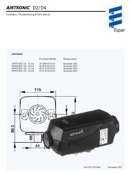
Water Heaters<br />
Installation Instructions<br />
<strong>BBW</strong> <strong>46</strong><br />
<strong>DBW</strong> <strong>46</strong><br />
Be sure to read these Operating Instructions<br />
prior to putting the heater into operation.<br />
9/1998
<strong>BBW</strong> <strong>46</strong> / <strong>DBW</strong> <strong>46</strong><br />
Table of Contents<br />
Page<br />
Installation Instructions 1<br />
Legal Provisions 1<br />
Installation Location 2<br />
Installation Example<br />
<strong>BBW</strong> <strong>46</strong> / <strong>DBW</strong> <strong>46</strong> 3<br />
Connection to the Cooling System 5<br />
Re-Positioning of Circulating Pump 5<br />
Fuel Circuit Connection 5<br />
Combustion Air Supply 8<br />
Exhaust Gas Pipe 8<br />
Electrical Connections 8<br />
Allocation of Telestart T60 9<br />
Installation of Telestart Receiver 9<br />
Circuit Diagrams 12<br />
Initial Start-Up 13<br />
Technical Data 14<br />
Version 15<br />
I
<strong>BBW</strong> <strong>46</strong> / <strong>DBW</strong> <strong>46</strong><br />
Installation Instructions<br />
Legal Provisions for Installation<br />
For testing the heater in accordance with Section 19, 20 or<br />
21 StVZO (German Regulations Authorising the Use of Vehicles<br />
for Road Traffic) the following regulations are primarily<br />
to be observed (Section 22 a StVZO):<br />
NOTE:<br />
These provisions are binding within the scope of the<br />
StVZO and should also be observed in countries<br />
where no special locally applicable regulations are in<br />
effect!<br />
Within the scope of the StVZO ”General Design Certifications”<br />
have been granted by the Federal Office for Motor<br />
Traffic for the <strong>BBW</strong> <strong>46</strong> and <strong>DBW</strong> <strong>46</strong> water heaters with the<br />
following design approval numbers:<br />
~ S 185 for heaters <strong>BBW</strong> <strong>46</strong> - petrol<br />
~ S 186 for heaters <strong>DBW</strong> <strong>46</strong> - diesel<br />
The installation of the heaters must be performed in accordance<br />
with these Installation Instructions. The installation<br />
must be checked<br />
a) upon the homologation of the vehicles<br />
in accordance with Section 20 StVZO<br />
b) upon any individual test<br />
in accordance with Section 21 StVZO, or<br />
c) upon any examination<br />
in accordance with Section 19 StVZO by a<br />
registered expert or examiner for motor traffic, an<br />
expert for automotive vehicles, or any other<br />
authorised official, in accordance with Paragraph<br />
7.4 a of Appendix VIII to the StVZO,<br />
and in the case of item c) the proper installation must be<br />
certified on the approval certificate contained on the design<br />
certification stating the following:<br />
- vehicle manufacturer<br />
- vehicle type and<br />
vehicle identification number.<br />
The effectiveness of the design certification is dependent<br />
on this certificate. The approval certification is to be kept in<br />
the vehicle.<br />
The year of initial operation must be durably marked by the<br />
installer on the type plate of the heater by removing the<br />
years that are not applicable.<br />
Extracting the combustion air from the interior of the<br />
vehicle is not permissible.<br />
The discharge opening of the exhaust pipe should point upward,<br />
sideways, or in the case that the exhaust pipes are<br />
routed on the underside of the bottom of the vehicle, it<br />
must be positioned near the lateral or rear edge of the<br />
driver’s cab or vehicle.<br />
Exhaust pipes must be routed so that the possibility of exhaust<br />
fumes entering the interior of the vehicle is remote.<br />
The functioning of any parts of the vehicle essential for its<br />
operation must not be impaired.<br />
The openings of the combustion air inlet and exhaust gas<br />
outlet pipes must be so designed that a spherical object of<br />
16 mm dia. cannot be introduced.<br />
Electric lines, switchgear and controlgear of the heater<br />
must be so arranged in the vehicle that their functioning<br />
cannot be impaired under normal operating conditions.<br />
For the routing of fuel lines and the installation of additional<br />
fuel tanks, Sections 45 and <strong>46</strong> StVZO are to be<br />
adhered to. The most important excerpts therefrom are as<br />
follows:<br />
Fuel lines must be designed in such a way that they remain<br />
unaffected by torsional stresses in the vehicle, engine<br />
movement, and the like. They must be protected<br />
against mechanical damage. All parts of the fuel system<br />
must be protected against heat which would impair their<br />
operation, and must be located such that dripping or evaporating<br />
fuel can neither collect nor be ignited by hot components<br />
or electrical equipment.<br />
The heater must not be installed in spaces occupied by<br />
persons.<br />
The operating state of the heater at any given time – at<br />
least an indication as to whether it is “on” or “off” - must be<br />
easily recognisable.<br />
The installation of components which are not of an approved<br />
type will lead to the revocation of the General Design<br />
Certification of the heater and thus the General Operating<br />
Permit of the entire vehicle. The same applies to improperly<br />
performed repairs or those where other than genuine<br />
replacement parts have been used.<br />
Use of the Water Heater<br />
The <strong>BBW</strong> <strong>46</strong> / <strong>DBW</strong> <strong>46</strong> water heaters, in conjunction with<br />
the vehicle’s heating system, are used for<br />
- heating the passenger compartment,<br />
- defrosting the vehicle’s windows,<br />
- preheating water-cooled engines.<br />
The water heaters operate independently of the vehicle’s<br />
engine and are connected to the cooling system, the fuel<br />
system and the electrical system of the vehicle.<br />
1
<strong>BBW</strong> <strong>46</strong> / <strong>DBW</strong> <strong>46</strong><br />
Installation Location<br />
Preferably, the heater should be installed in the engine<br />
compartment in the splash-water protected area of the<br />
front fenders or at the splash wall.<br />
2<br />
2<br />
The heater should be installed at a level as low as possible<br />
so as to ensure automatic venting of the heater and the circulating<br />
pump. . This is of special importance since the circulating<br />
pump is not of the self-priming type.<br />
CAUTION:<br />
The openings of the water connecting pipe sockets must<br />
never, not any installation position, point downward.<br />
CAUTION:<br />
The heater must not be installed :<br />
- in the immediate vicinity of or above hot vehicle parts<br />
- in the direct splashwater area of the wheels<br />
1<br />
4<br />
6<br />
3<br />
4<br />
5<br />
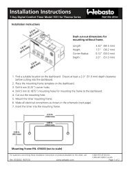
1 Fuel inlet<br />
2 Water outlet<br />
3 Water inlet<br />
4 Exhaust gas outlet<br />
5 Heater mount<br />
6 Combustion air inlet<br />
Fig 1:<br />
Installation Positions<br />
Fig 2: Installation Drawing <strong>BBW</strong> <strong>46</strong> / <strong>DBW</strong> <strong>46</strong><br />
Type Plate<br />
The type plate must be located at a place where it is protected<br />
against damage and where it can be easily viewed<br />
once the heater has been installed (or else, a type plate duplicate<br />
is to be used).<br />
The years not applicable must be removed from the type<br />
plate.<br />
Mount<br />
The heater mount must be fitted to the vehicle body or the<br />
intermediate support by means of at least four M6 screws.<br />
It is required that washers and lock washers be used.<br />
In the case of level body surfaces, the washers must have<br />
a minimum diameter of 22 mm.<br />
Do not use sheet metal screws for attaching the mount.<br />
2
<strong>BBW</strong> <strong>46</strong> / <strong>DBW</strong> <strong>46</strong><br />
Cable harness<br />
Fuel line<br />
Heater fuel line<br />
Exhaust gas line<br />
Water circuit<br />
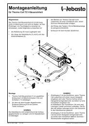
Fig 3: Installation example of <strong>BBW</strong> <strong>46</strong> / <strong>DBW</strong> <strong>46</strong> heating device in a passenger car (inline integration)<br />
1 Radiator<br />
8 Control unit<br />
2 Cooling water thermostat<br />
9 Relay (for vehicle fan)<br />
3 Water pump (of vehicle engine)<br />
10 Regulating valve of vehicle heating<br />
4 Vehicle engine with standard equipment<br />
11 Heat exchanger of vehicle heating<br />
5 Water heater<br />
12 Vehicle heating fan<br />
6 Battery<br />
13 Switch for vehicle heating fan<br />
7 Fuse holder<br />
14 Fuse bank in vehicle<br />
15 Digital timer<br />
16 Fuel extractor<br />
17 Fuel metering pump<br />
18 Exhaust silencer<br />
19 Circulating pump<br />
3
<strong>BBW</strong> <strong>46</strong> / <strong>DBW</strong> <strong>46</strong><br />
Cable harness<br />
Fuel line<br />
Heater fuel line<br />
Exhaust gas line<br />
Water circuit<br />
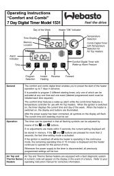
Fig 4: Installation example of <strong>BBW</strong> <strong>46</strong> / <strong>DBW</strong> <strong>46</strong> heating device in a passenger car (thermostat integration)<br />
1 Radiator<br />
7 Fuse holder<br />
2 Cooling water thermostat<br />
8 Control unit<br />
3 Water pump(of vehicle engine)<br />
9 Relay (for vehicle fan)<br />
4 Vehicle engine with standard equipment<br />
10 Regulating valve for vehicle heating<br />
5 Water heater<br />
11 Heat exchanger, vehicle heating<br />
5A Non-return valve<br />
12 Vehicle heating fan<br />
6 Battery<br />
13 Switch for vehicle heating fan<br />
14 Fuse bank in vehicle<br />
15 Digital timer<br />
16 Fuel pick-up<br />
17 Fuel metering pump<br />
18 Exhaust silencer<br />
19 Circulating pump<br />
20 Thermostat<br />
4
<strong>BBW</strong> <strong>46</strong> / <strong>DBW</strong> <strong>46</strong><br />
Connection to the Vehicle’s Cooling System<br />
The heater is to be connected to the vehicle’s cooling system<br />
in accordance with Figs 3, 4, 5 and 6. A minimum of 4<br />
litres of coolant must be maintained in the cooling circuit.<br />
7<br />
1 2 3 4 5<br />
6<br />
The integration of the heater into the cooling circuit is to be<br />
performed in the flow line of the vehicle’s heat exchanger.<br />
As a rule, the water hoses supplied by Webasto with the<br />
heater should be used. If this is not the case, the hoses<br />
must comply with DIN 73411 requirements as a minimum.<br />
The hoses are to be routed without any kinks and – to<br />
ensure proper venting – in an upward pitch, if<br />
possible. Hose connections must be secured against<br />
slipping off by means of hose clamps.<br />
NOTE:<br />
When securing the hose clamps to the heater, be sure to<br />
fit them between the bead (thicker part) of the hose and<br />
the heater.<br />
The hose clamps must be tightened to a torque of 2.0 +<br />
0.5 Nm.<br />
Connection to the Fuel System<br />
Fuel system integration without non-return valve<br />
in the tank<br />
The heater’s fuel supply circuit must be integrated in the return<br />
line as shown in Fig. 3.<br />
Fuel system integration with non-return valve in the<br />
tank or fuel system integration in the case of singleline<br />
fuel supply<br />
Tank extractor with 90°-elbow is to be installed in the tank<br />
fitting (Fig. 7)<br />
5<br />
Fig 5:<br />
7<br />
1<br />
Integration into Engine/Water<br />
Circuit “Inline Integration”<br />
2<br />
3<br />
8<br />
4<br />
9<br />
5<br />
Before the heater is started up for the first time, or after the<br />
coolant has been replaced, it must be ensured that the<br />
cooling system is properly bled. Heater and piping should<br />
be installed in such a way that static bleeding of the system<br />
is ensured.<br />
During heating operation, inadequate bleeding may lead to<br />
a malfunction due to overheating.<br />
8,5<br />
500<br />
Fig 6:<br />
Integration into Engine/Water<br />
Circuit “Thermostat Integration”<br />
Legend of Figs. 5 and 6:<br />
1 Expansion tank<br />
2 Thermostat<br />
3 Vehicle engine<br />
4 Circulating pump<br />
5 Heating device<br />
6 Heat exchanger of heater<br />
7 Radiator<br />
8 Thermostat<br />
9 Non-return valve<br />
6<br />
Re-Positioning of Circulating Pump<br />
The circulating pump may be integrated into the water circuit<br />
either by installation at the location provided on the<br />
heater or at a heater-remote location.<br />
It is important that the correct direction of flow through the<br />
heater be observed (water outlet at top / water inlet at<br />
bottom) as otherwise malfunctions will occur!<br />
Bild 7: Tankarmatur 90°<br />
Lochbild<br />
Mindestabstand 25 mm<br />
Bild 8: Webasto-Tankentnehmer<br />
5
<strong>BBW</strong> <strong>46</strong> / <strong>DBW</strong> <strong>46</strong><br />
Fuel Supply<br />
Details on the permissible pressure at the fuel extraction<br />
point are contained in the table below.<br />
l 1<br />
l 2<br />
l 1 + l2 ≤ 13 m<br />
l 1 ≤ 3 m<br />
l 2 ≤ 10 m<br />
Fig 9:<br />
Fuel Supply<br />
l 2<br />
l 1<br />
Permissible<br />
fuel feed height H (m)<br />
at max. permissible<br />
overpressure (bar) in fuel<br />
line<br />
0.00 1.5<br />
1.25 1.4<br />
2.50 1.3<br />
3.75 1.2<br />
5.00 1.1<br />
6.25 1.0<br />
7.50 0.9<br />
8.75 0.8<br />
10.00 0.7<br />
Permissible fuel suction<br />
height S (m)<br />
at max. permissible<br />
underpressure (bar) in fuel<br />
tank<br />
petrol diesel<br />
0.00 -0.15 -0.15<br />
0.50 -0.11 -0.11<br />
1.00 – -0.07<br />
NOTE<br />
A fuel flow line can usually be identified by the in-line fuel<br />
filter.<br />
NOTE:<br />
If the vehicle’s fuel system is equipped with a vapour separator,<br />
fuel extraction is to take place upstream of same.<br />
For fuel extraction from flow or return lines it is imperative<br />
that the special Webasto fuel pick-up (see Fig. 10) be<br />
used.<br />
from tank<br />
Fig 10:<br />
to engine<br />
to metering pump<br />
Webasto Fuel Pick-Up<br />
The fuel pick-up is to be mounted so that any air or gas<br />
bubbles that may form are automatically discharged toward<br />
the tank (see Fig. 10).<br />
Air or gas bubbles in the fuel line of the vehicle can form if<br />
there is a leak in the vehicle’s carburettor or fuel pump, or<br />
if the ambient temperature exceeds the evaporating temperature<br />
of the fuel.<br />
Fuel should not be extracted in the vicinity of the engine<br />
since here gas bubbles are likely to form in the lines owing<br />
to the heat radiating from the engine, which may result in<br />
malfunctions of the combustion operation.<br />
6
<strong>BBW</strong> <strong>46</strong> / <strong>DBW</strong> <strong>46</strong><br />
If the heater is installed in vehicles with petrol injection systems<br />
it must therefore be determined whether whether the<br />
fuel pump is mounted inside or outside the tank.<br />
Where the fuel pump is located inside the tank, the fuel<br />
can only be drawn from the return pipe in which case it<br />
must be ensured that the return pipe extends almost to the<br />
bottom of the tank. If this is not the case, it is possible to<br />
extend the return pipe.<br />
Where the fuel pump is mounted outside the tank, the connection<br />
to the fuel system can be accomplished between<br />
the fuel tank and the fuel pump.<br />
Connecting Two Pipes Using a Hose<br />
The proper connection of fuel lines using a hose is shown<br />
in Fig. 11.<br />
Check for leaks!<br />
correct<br />
clamp<br />
Fuel Lines<br />
NOTE:<br />
The hose clamps are to be tightened to a torque of 1.0 +<br />
0.4 Nm.<br />
Any fuel that may have leaked is to be removed from the<br />
engine or heater prior to starting up the heater or engine.<br />
Only steel, copper and plastic pipes made of plasticised,<br />
light-resistant and temperature-stabilised PA 11<br />
or PA 12 (e.g. Mecanyl RWTL) in accordance with DIN<br />
73378 may be used as fuel lines.<br />
As in the majority of cases it is not possible to route the<br />
lines in a continuous upward pitch, the inside diameter<br />
must not exceed a given dimension. If the inside diameter<br />
is larger than 4 mm, air or gas bubbles accumulate which<br />
result in malfunctions if the lines sag or are routed in a<br />
downward pitch. If the diameters shown in Fig. 9 are used<br />
you can be sure that no unwanted bubbles will form.<br />
The lines leading from the metering pump to the heater<br />
should not be routed in a downward pitch.<br />
To prevent the fuel lines from sagging, freely suspended<br />
lines must be secured. Mounting should be performed in<br />
such a manner that the lines are protected against flying<br />
stones and thermal influence (exhaust pipe).<br />
wrong<br />
Fig 11:<br />
bubble<br />
Metering Pump<br />
Pipe/Hose Connection<br />
bubble<br />
The metering pump is a combined fuel delivery, metering<br />
and shutoff system and is subject to certain installation<br />
criteria (see Figs. 8 and 11).<br />
Fig 12:<br />
Metering Pump without Diaphragm Damper<br />
Installation position and mounting<br />
Installation Location<br />
Prior to installing the metering pump make sure that the<br />
maximum pressure prevailing at the fuel extraction point is<br />
lower than the max. permissible value indicated in the<br />
table on page 6.<br />
It is recommended that the metering pump be installed in a<br />
location which sufficiently cool. On no account must the<br />
permissible ambient temperature at any given operating<br />
state be in excess of + 20°C.<br />
Metering pump and fuel lines must not be mounted within<br />
the radiation range of hot vehicle parts. If necessary, a radiation<br />
protection is to be provided.<br />
The preferred installation location is near the tank.<br />
Installation and Mounting<br />
The metering pump is to be attached by vibration-damping<br />
suspension. The installation position is restricted as shown<br />
in Fig. 12 in order to ensure proper self-ventilation of the<br />
system.<br />
7
<strong>BBW</strong> <strong>46</strong> / <strong>DBW</strong> <strong>46</strong><br />
Combustion Air Supply<br />
Electrical Connections<br />
The combustion air required must be drawn in from the outside<br />
of the vehicle.<br />
The combustion air should be drawn in at a splash-water<br />
protected location.<br />
The combustion air intake opening must be so located that<br />
the possibility of clogging due to contamination is remote.<br />
It must not point in the direction of travel.<br />
The combustion air line can be so routed that it features several<br />
bends (total of 270°, smallest bending radius 50 mm).<br />
The combustion air line can have a length of max. 1000 mm.<br />
Fig 13:<br />
Exhaust silencer<br />
Direction of flow (optional)<br />
Control Unit/Heater Connection<br />
The electrical connection of the heaters is to be performed<br />
in accordance with Fig. 16.<br />
The connection of the digital timer should be carried out in<br />
accordance with the circuit diagram shown in Fig. 15.<br />
Vehicle Fan<br />
The activation of the vehicle fan is controlled by the vehicle<br />
fan relay, see circuit diagram shown in Fig. 16.<br />
On no account should the combustion air be extracted<br />
from areas occupied by persons. If the heater is located in<br />
an enclosed installation casing, a ventilation opening of at<br />
least 3 cm2 is required.<br />
Where the heater is installed in the vicinity of the vehicle tank<br />
in a common installation space, combustion air must be<br />
drawn in from the outside of the vehicle and the exhaust gas<br />
be discharged to the atmosphere. The lead-through openings<br />
must be splash-proof.<br />
Exhaust Pipe<br />
The exhaust pipe (inside diameter 22 mm) may have a<br />
length of up to 5m and may feature several bends (in total<br />
720°, smallest bending radius 50 mm).<br />
The exhaust silencer is preferably to be mounted in the vicinity<br />
of the heater.<br />
It must not be installed near the combustion air intake<br />
opening.<br />
Operation of the <strong>BBW</strong> <strong>46</strong> / <strong>DBW</strong> <strong>46</strong> heater is also permissible<br />
without silencer.<br />
The discharge opening of the exhaust pipe must not point<br />
in the direction of travel (see Fig. 14).<br />
direction of discharge approximately vertical 90° ± 10°<br />
Fig 14: Exhaust Pipe Discharge Opening<br />
Installation Position<br />
Rigid pipes made of unalloyed steel with a minimum wall<br />
thickness of 1.0 mm or flexible tubes of alloyed steel<br />
should be used as exhaust pipes.<br />
NOTE:<br />
Any condensation water that may have collected in the exhaust<br />
pipe must be drained immediately. If necessary, it is<br />
permitted to drill a condensation water drain hole.<br />
Connection of Telestart Receiver T60<br />
The connection of Telestart receiver T60 is to be carried<br />
out as shown in Fig. 16.<br />
8
<strong>BBW</strong> <strong>46</strong> / <strong>DBW</strong> <strong>46</strong><br />
Tuning of Telestart T60 Handheld Transmitter and Receiver<br />
NOTE:<br />
Each receiver can be allocated 2 handheld transmitters.<br />
- Place batteries in battery compartment.<br />
- Pull antenna out of transmitter approx. 5 cm.<br />
-<br />
25 15 1<br />
A A A<br />
Wait 10 seconds<br />
Interrupt voltage supply for at least 10 seconds by removing<br />
the 15A flat fuse (blue).<br />
NOTE:<br />
If the Telestart receiver is retrofitted, fuse F2, 1A (black)<br />
has to be removed.<br />
Wait 5 seconds<br />
- Briefly press the ”Start” button.<br />
Start<br />
Operation indicator on transmitter is flashing.<br />
Wait 15 seconds<br />
- Briefly press the ”Off” button.<br />
Off<br />
Operation indicator on transmitter no longer flashes.<br />
- Tuning is finished.<br />
Retrofitting the T60 Telestart Receiver<br />
NOTE:<br />
The <strong>BBW</strong> <strong>46</strong> / <strong>DBW</strong> <strong>46</strong> water heaters can be retrofitted<br />
with the T60 Telestart remote control.<br />
The retrofit kit T60 consists of the following parts:<br />
- Transmitter T60 with 2 alkaline LR1 1.5V batteries<br />
- Standard antenna T6<br />
- Receiver T6<br />
- Mounting hardware (bag) comprising<br />
2 sheet metal screws<br />
1 receptacle housing<br />
1 tab connector housing<br />
3 push-on receptacles<br />
The installation may only be performed by authorised Webasto<br />
service centres.<br />
CAUTION:<br />
The receiver must be installed in the interior of the vehicle.<br />
It is not permitted to extend the cable harness (approx. 70<br />
cm long) provided on the receiver.<br />
- Determine suitable installation location for receiver T6 in<br />
the interior of the vehicle, in the vicinity of the digital<br />
timer.<br />
- Mount receiver using the sheet-metal screws (contained<br />
in the kit).<br />
25 15 1<br />
A A A<br />
Off<br />
If any specified time period is exceeded or fallen short of,<br />
tuning will not be successful and the procedure is to be repeated<br />
from the beginning.<br />
Proceed in the same way for tuning and thus allocating a<br />
second transmitter.<br />
- Immediately after reinstalling the flat fuse press the ”Off”<br />
button.<br />
9
<strong>BBW</strong> <strong>46</strong> / <strong>DBW</strong> <strong>46</strong><br />
Installation of Antenna<br />
NOTE:<br />
Preferably, the antenna should be installed in the interior<br />
of the vehicle, at the top in the centre of the windshield or<br />
rear window. If installed at different locations, the range is<br />
likely to be diminished.<br />
- Route antenna cable to receiver.<br />
- Establish plug connection at receiver and tighten connector<br />
hand-tight.<br />
- Secure antenna cable using cable ties.<br />
For an optimal reception, a distance of 2 ± 0.5 cm from the<br />
windshield edge is to be maintained (Fig. 15). The cable<br />
should be routed upward, beneath the panelling in the vehicle<br />
roof and then directed to the right or left to the<br />
chassis member.<br />
NOTE:<br />
In the case of lack of space, the antenna may be installed<br />
up to 15 cm off-centre.<br />
- Clean windshield or rear window using grease-dissolving<br />
cleaner (e.g. methylated spirits).<br />
- Peel off protective film from antenna and glue antenna<br />
in place.<br />
Antenna<br />
2 ± 0.5 cm<br />
Fig 15:<br />
Installation of Antenna<br />
NOTE:<br />
Do neither shorten nor sharply bend antenna cable.<br />
10
<strong>BBW</strong> <strong>46</strong> / <strong>DBW</strong> <strong>46</strong><br />
M1<br />
B1<br />
E B2 R1 X1 F3<br />
M2<br />
A B C D<br />
6 5 4 2<br />
3 2 1 1<br />
2<br />
1<br />
8 7 6 5<br />
4 3 2 1<br />
2<br />
1<br />
4<br />
3<br />
6 8 10 12<br />
5 7 9 11<br />
X1<br />
br<br />
ge<br />
X1<br />
(75) 15<br />
30<br />
61<br />
P<br />
A4<br />
rt<br />
sw<br />
br<br />
X1 Y1<br />
1<br />
2 bl/ge 2<br />
3 gr<br />
3<br />
4 vi<br />
4<br />
5<br />
6<br />
7<br />
br<br />
rt<br />
sw<br />
5<br />
6<br />
7<br />
8 ge<br />
8<br />
30<br />
E1<br />
E2<br />
31<br />
K7<br />
87b<br />
X2 Y2<br />
9<br />
87<br />
87a<br />
87a<br />
K6<br />
rt/bl<br />
87<br />
86<br />
30 85<br />
S2<br />
A1<br />
31<br />
Fig 16: Automatic control circuit <strong>BBW</strong> <strong>46</strong> / <strong>DBW</strong> <strong>46</strong>, 12V digital timer and Telestart T6 (legend see page 12)<br />
sw<br />
br<br />
M<br />
rt<br />
F4 F2 F1<br />
W1<br />
B3<br />
S1<br />
M3<br />
W1<br />
W1 A<br />
sw/rt 3<br />
4<br />
1<br />
S3<br />
W1<br />
rt<br />
gn/ws 6<br />
ws/sw<br />
br<br />
br<br />
br<br />
br<br />
5<br />
2<br />
X1<br />
bl bl<br />
bl<br />
br<br />
11<br />
1 2 1<br />
Y<br />
2<br />
bl ge/rt<br />
6<br />
12 2<br />
3<br />
sw sw<br />
br<br />
1<br />
br<br />
vi vi<br />
3<br />
1<br />
4<br />
rt<br />
5<br />
4<br />
rt<br />
6<br />
rt<br />
or or<br />
7<br />
8<br />
gn gn<br />
gn<br />
8<br />
7<br />
24V<br />
ws ws<br />
M<br />
M<br />
F3 ϑ<br />
R1<br />
ϑ<br />
M2 M1 B1 B2<br />
9<br />
5<br />
R2<br />
10<br />
X2<br />
12V<br />
br<br />
1<br />
2<br />
ge ge ge<br />
A2<br />
2<br />
E<br />
11
<strong>BBW</strong> <strong>46</strong> / <strong>DBW</strong> <strong>46</strong><br />
Wire Cross-Sections<br />
Wire Colours<br />
bl blue<br />
< 7.5 m 7.5 - 15 m<br />
0.5 mm 2 0.75 mm 2 br brown<br />
ge yellow<br />
0.75 mm 2 1.5 mm 2 gn green<br />
gr grey<br />
1.5 mm 2 2.5 mm 2 or orange<br />
2.5 mm 2 4.0 mm 2 rt red<br />
sw black<br />
4.0 mm 2 6.0 mm 2 vi violet<br />
ws white<br />
Pos. Designation Remarks<br />
A1 Heater <strong>BBW</strong> <strong>46</strong> / <strong>DBW</strong> <strong>46</strong><br />
A2 Electronic control unit SG 1560<br />
A4 Telestart receiver T 6<br />
B1 Flame detector<br />
B2 Temperature sensor<br />
B3 Room thermostat for vehicle fan on/off<br />
E Glow plug<br />
F1 Fuse 16A motor vehicle fuse DIN 72581<br />
F2 Fuse 8A motor vehicle fuse DIN 72581<br />
F3 Temperature fuse<br />
F4 Fuse 16A motor vehicle fuse DIN 72581<br />
K6 Relay for vehicle fan<br />
K7 Relay for Telestart receiver<br />
M1 Motor combustion air fan<br />
M2 Motor circulating pump<br />
M3 Motor vehicle fan<br />
P Timer, digital for presetting operating time<br />
R1 Resistor for part-load operation<br />
R2 Resistor only required for 12-volt glow plugs in a 24-volt heater<br />
S1 Switch for vehicle fan S1 or S2 depending on vehicle<br />
S2 Switch for vehicle fan S1 or S2 depending on vehicle<br />
S3 Switch for circulating pump for separate activation<br />
V3 Diode (in pos. A2)<br />
V108 Transistor (in pos. A2)<br />
W1 Cable harness<br />
X1 Connector 12-pole<br />
X2 Connector 2-pole<br />
X4 Connector 1-pole<br />
Y Metering pump<br />
12
<strong>BBW</strong> <strong>46</strong> / <strong>DBW</strong> <strong>46</strong><br />
Initial Operation<br />
NOTE:<br />
The safety information contained in the Operating Instructions<br />
have to be adhered to!<br />
After the heater has been installed, the water circuit and<br />
the fuel supply system are to be thoroughly bled. Follow<br />
the directions of the vehicle manufacturer.<br />
Perform a test run of the heater thereby checking all water<br />
and fuel connections for leakage and security. Should the<br />
heater fail during operation, troubleshooting activities are<br />
to be carried out.<br />
Malfunctions<br />
Fault Lock-Out Due to Malfunctions of the Heater<br />
If no flame forms fuel is delivered for max. 180 seconds.<br />
If the flame is extinguished during operation, fuel is delivered<br />
for max. 90 seconds.<br />
In the event of overheating fuel supply is immediately<br />
stopped.<br />
CAUTION:<br />
No visual indication occurs in the case of overheating.<br />
Fault Lock-Out Due to Undervoltage<br />
In the case of an undervoltage of 9.5 ± 0. V (in the case of<br />
12-volt heaters) or 19 ± 1 V (in the case of 24-volt<br />
heaters), measured at the input of the control unit, occurring<br />
over a period of 20 seconds, the heater will shut down<br />
in its fault lock-out mode and an after-run period will follow.<br />
Interlock Deactivation<br />
- Eliminate cause of malfunction<br />
- Resetting is performed by switching the heater off and<br />
back on again (the ’off’ period has to last for at least<br />
1 sec).<br />
- In the case of overheating, the temperature fuse has to<br />
be replaced or the temperature limiter to be reset.<br />
13
<strong>BBW</strong> <strong>46</strong> / <strong>DBW</strong> <strong>46</strong><br />
Technical Data<br />
Unless tolerances are shown within the technical data<br />
table, a tolerance of ± 10% applies at an ambient temperature<br />
of +20°C and at the rated voltage.<br />
Fuel for <strong>BBW</strong> <strong>46</strong> (Petrol):<br />
The type of fuel specified by the vehicle manufacturer is<br />
suitable as fuel for the heater.<br />
Fuel for <strong>DBW</strong> <strong>46</strong> (Diesel):<br />
The diesel fuel specified by the vehicle manufacturer is<br />
suitable as fuel for the heater. When changing to cold-resistant<br />
fuels, the heater must be operated for about 15<br />
minutes to ensure that the fuel line and fuel pump are also<br />
filled with the new fuel.<br />
Any negative effect caused by additives is not known.<br />
Heater<br />
Operating<br />
Mode<br />
<strong>BBW</strong> <strong>46</strong> <strong>DBW</strong> <strong>46</strong><br />
Mark of approval ~S 185 ~S 186<br />
Type<br />
water heater with vaporising burner<br />
Heat output<br />
full load<br />
part load<br />
4.6 kW<br />
2.3 kW<br />
Fuel petrol diesel<br />
Fuel consumption<br />
Rated voltage<br />
Operating voltage range<br />
Rated power consumption without<br />
circulating pump (without vehicle fan)<br />
Max. permissible ambient temperature:<br />
Heater: - operation<br />
- storage<br />
Control unit: - operation<br />
- storage<br />
Metering pump: - operation<br />
- storage<br />
Max. allowable working pressure (heat carrier)<br />
Filling capacity of heat exchanger<br />
Min. amount to be maintained in the circuit<br />
Volume flow of circulating pump against 0.1 bar<br />
CO 2 content in exhaust gas (perm. funct. range)<br />
Dimensions of heater<br />
Weight incl. control unit and circulating pump<br />
full load<br />
part load<br />
full load<br />
part load<br />
0.63 l/h<br />
0.23 l/h<br />
0.58 l/h<br />
0.29 l/h<br />
12 or 24 volts<br />
10 ... 14 volts or 20 ... 28 volts<br />
44 W<br />
33 W<br />
-40° ... + 80°C<br />
-40° ... +100°C<br />
-40° ... + 75°C<br />
-40° ... + 85°C<br />
-40° ... + 20°C<br />
-40° ... + 85°C<br />
0.4 ... 2.0 bar<br />
0.25 l<br />
4.00 l<br />
950 l/h<br />
10 ... 10.5 % by vol.<br />
length 277 mm<br />
width 148 mm<br />
height 197 mm<br />
3.9 kg<br />
14
Version<br />
<strong>BBW</strong> <strong>46</strong> / <strong>DBW</strong> <strong>46</strong><br />
Type<br />
<strong>DBW</strong> <strong>46</strong> Supplementary Heater<br />
Water heater for ”diesel” fuel<br />
Type<br />
<strong>BBW</strong> <strong>46</strong> Supplementary Heater<br />
Water heater for ”petrol” fuel<br />
The <strong>BBW</strong> <strong>46</strong> / <strong>DBW</strong> <strong>46</strong> water<br />
heaters are designed for 12-volt or<br />
24-volt operation.<br />
15