BBW - DBW 46 - VW-Bus-T4.de
BBW - DBW 46 - VW-Bus-T4.de
BBW - DBW 46 - VW-Bus-T4.de

You also want an ePaper? Increase the reach of your titles
YUMPU automatically turns print PDFs into web optimized ePapers that Google loves.
<strong>BBW</strong> <strong>46</strong> / <strong>DBW</strong> <strong>46</strong><br />
Combustion Air Supply<br />
Electrical Connections<br />
The combustion air required must be drawn in from the outside<br />
of the vehicle.<br />
The combustion air should be drawn in at a splash-water<br />
protected location.<br />
The combustion air intake opening must be so located that<br />
the possibility of clogging due to contamination is remote.<br />
It must not point in the direction of travel.<br />
The combustion air line can be so routed that it features several<br />
bends (total of 270°, smallest bending radius 50 mm).<br />
The combustion air line can have a length of max. 1000 mm.<br />
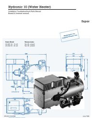
Fig 13:<br />
Exhaust silencer<br />
Direction of flow (optional)<br />
Control Unit/Heater Connection<br />
The electrical connection of the heaters is to be performed<br />
in accordance with Fig. 16.<br />
The connection of the digital timer should be carried out in<br />
accordance with the circuit diagram shown in Fig. 15.<br />
Vehicle Fan<br />
The activation of the vehicle fan is controlled by the vehicle<br />
fan relay, see circuit diagram shown in Fig. 16.<br />
On no account should the combustion air be extracted<br />
from areas occupied by persons. If the heater is located in<br />
an enclosed installation casing, a ventilation opening of at<br />
least 3 cm2 is required.<br />
Where the heater is installed in the vicinity of the vehicle tank<br />
in a common installation space, combustion air must be<br />
drawn in from the outside of the vehicle and the exhaust gas<br />
be discharged to the atmosphere. The lead-through openings<br />
must be splash-proof.<br />
Exhaust Pipe<br />
The exhaust pipe (inside diameter 22 mm) may have a<br />
length of up to 5m and may feature several bends (in total<br />
720°, smallest bending radius 50 mm).<br />
The exhaust silencer is preferably to be mounted in the vicinity<br />
of the heater.<br />
It must not be installed near the combustion air intake<br />
opening.<br />
Operation of the <strong>BBW</strong> <strong>46</strong> / <strong>DBW</strong> <strong>46</strong> heater is also permissible<br />
without silencer.<br />
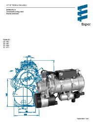
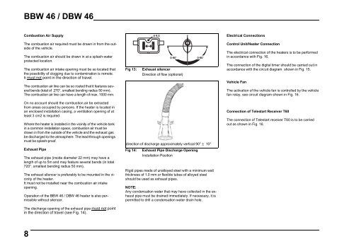
The discharge opening of the exhaust pipe must not point<br />
in the direction of travel (see Fig. 14).<br />
direction of discharge approximately vertical 90° ± 10°<br />
Fig 14: Exhaust Pipe Discharge Opening<br />
Installation Position<br />
Rigid pipes made of unalloyed steel with a minimum wall<br />
thickness of 1.0 mm or flexible tubes of alloyed steel<br />
should be used as exhaust pipes.<br />
NOTE:<br />
Any condensation water that may have collected in the exhaust<br />
pipe must be drained immediately. If necessary, it is<br />
permitted to drill a condensation water drain hole.<br />
Connection of Telestart Receiver T60<br />
The connection of Telestart receiver T60 is to be carried<br />
out as shown in Fig. 16.<br />
8