BBW - DBW 46 - VW-Bus-T4.de
BBW - DBW 46 - VW-Bus-T4.de
BBW - DBW 46 - VW-Bus-T4.de

You also want an ePaper? Increase the reach of your titles
YUMPU automatically turns print PDFs into web optimized ePapers that Google loves.
<strong>BBW</strong> <strong>46</strong> / <strong>DBW</strong> <strong>46</strong><br />
If the heater is installed in vehicles with petrol injection systems<br />
it must therefore be determined whether whether the<br />
fuel pump is mounted inside or outside the tank.<br />
Where the fuel pump is located inside the tank, the fuel<br />
can only be drawn from the return pipe in which case it<br />
must be ensured that the return pipe extends almost to the<br />
bottom of the tank. If this is not the case, it is possible to<br />
extend the return pipe.<br />
Where the fuel pump is mounted outside the tank, the connection<br />
to the fuel system can be accomplished between<br />
the fuel tank and the fuel pump.<br />
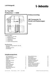
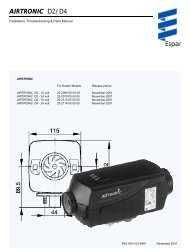
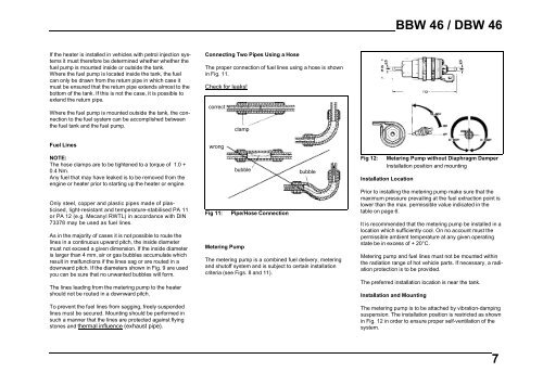
Connecting Two Pipes Using a Hose<br />
The proper connection of fuel lines using a hose is shown<br />
in Fig. 11.<br />
Check for leaks!<br />
correct<br />
clamp<br />
Fuel Lines<br />
NOTE:<br />
The hose clamps are to be tightened to a torque of 1.0 +<br />
0.4 Nm.<br />
Any fuel that may have leaked is to be removed from the<br />
engine or heater prior to starting up the heater or engine.<br />
Only steel, copper and plastic pipes made of plasticised,<br />
light-resistant and temperature-stabilised PA 11<br />
or PA 12 (e.g. Mecanyl RWTL) in accordance with DIN<br />
73378 may be used as fuel lines.<br />
As in the majority of cases it is not possible to route the<br />
lines in a continuous upward pitch, the inside diameter<br />
must not exceed a given dimension. If the inside diameter<br />
is larger than 4 mm, air or gas bubbles accumulate which<br />
result in malfunctions if the lines sag or are routed in a<br />
downward pitch. If the diameters shown in Fig. 9 are used<br />
you can be sure that no unwanted bubbles will form.<br />
The lines leading from the metering pump to the heater<br />
should not be routed in a downward pitch.<br />
To prevent the fuel lines from sagging, freely suspended<br />
lines must be secured. Mounting should be performed in<br />
such a manner that the lines are protected against flying<br />
stones and thermal influence (exhaust pipe).<br />
wrong<br />
Fig 11:<br />
bubble<br />
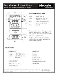
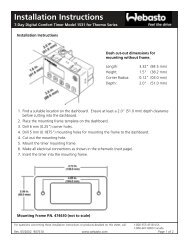
Metering Pump<br />
Pipe/Hose Connection<br />
bubble<br />
The metering pump is a combined fuel delivery, metering<br />
and shutoff system and is subject to certain installation<br />
criteria (see Figs. 8 and 11).<br />
Fig 12:<br />
Metering Pump without Diaphragm Damper<br />
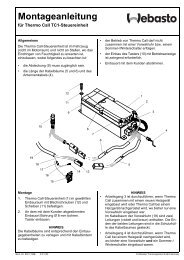
Installation position and mounting<br />
Installation Location<br />
Prior to installing the metering pump make sure that the<br />
maximum pressure prevailing at the fuel extraction point is<br />
lower than the max. permissible value indicated in the<br />
table on page 6.<br />
It is recommended that the metering pump be installed in a<br />
location which sufficiently cool. On no account must the<br />
permissible ambient temperature at any given operating<br />
state be in excess of + 20°C.<br />
Metering pump and fuel lines must not be mounted within<br />
the radiation range of hot vehicle parts. If necessary, a radiation<br />
protection is to be provided.<br />
The preferred installation location is near the tank.<br />
Installation and Mounting<br />
The metering pump is to be attached by vibration-damping<br />
suspension. The installation position is restricted as shown<br />
in Fig. 12 in order to ensure proper self-ventilation of the<br />
system.<br />
7